CN114102316A - A side grinding device for sheet metal processing - Google Patents
A side grinding device for sheet metal processing Download PDFInfo
- Publication number
- CN114102316A CN114102316A CN202210090416.1A CN202210090416A CN114102316A CN 114102316 A CN114102316 A CN 114102316A CN 202210090416 A CN202210090416 A CN 202210090416A CN 114102316 A CN114102316 A CN 114102316A
- Authority
- CN
- China
- Prior art keywords
- support
- auxiliary
- plate
- polishing
- pair
- Prior art date
- Legal status (The legal status is an assumption and is not a legal conclusion. Google has not performed a legal analysis and makes no representation as to the accuracy of the status listed.)
- Granted
Links
Images



Classifications
-
- B—PERFORMING OPERATIONS; TRANSPORTING
- B24—GRINDING; POLISHING
- B24B—MACHINES, DEVICES, OR PROCESSES FOR GRINDING OR POLISHING; DRESSING OR CONDITIONING OF ABRADING SURFACES; FEEDING OF GRINDING, POLISHING, OR LAPPING AGENTS
- B24B9/00—Machines or devices designed for grinding edges or bevels on work or for removing burrs; Accessories therefor
-
- B—PERFORMING OPERATIONS; TRANSPORTING
- B24—GRINDING; POLISHING
- B24B—MACHINES, DEVICES, OR PROCESSES FOR GRINDING OR POLISHING; DRESSING OR CONDITIONING OF ABRADING SURFACES; FEEDING OF GRINDING, POLISHING, OR LAPPING AGENTS
- B24B27/00—Other grinding machines or devices
- B24B27/0007—Movable machines
-
- B—PERFORMING OPERATIONS; TRANSPORTING
- B24—GRINDING; POLISHING
- B24B—MACHINES, DEVICES, OR PROCESSES FOR GRINDING OR POLISHING; DRESSING OR CONDITIONING OF ABRADING SURFACES; FEEDING OF GRINDING, POLISHING, OR LAPPING AGENTS
- B24B41/00—Component parts such as frames, beds, carriages, headstocks
- B24B41/02—Frames; Beds; Carriages
-
- B—PERFORMING OPERATIONS; TRANSPORTING
- B24—GRINDING; POLISHING
- B24B—MACHINES, DEVICES, OR PROCESSES FOR GRINDING OR POLISHING; DRESSING OR CONDITIONING OF ABRADING SURFACES; FEEDING OF GRINDING, POLISHING, OR LAPPING AGENTS
- B24B47/00—Drives or gearings; Equipment therefor
- B24B47/02—Drives or gearings; Equipment therefor for performing a reciprocating movement of carriages or work- tables
- B24B47/04—Drives or gearings; Equipment therefor for performing a reciprocating movement of carriages or work- tables by mechanical gearing only
-
- Y—GENERAL TAGGING OF NEW TECHNOLOGICAL DEVELOPMENTS; GENERAL TAGGING OF CROSS-SECTIONAL TECHNOLOGIES SPANNING OVER SEVERAL SECTIONS OF THE IPC; TECHNICAL SUBJECTS COVERED BY FORMER USPC CROSS-REFERENCE ART COLLECTIONS [XRACs] AND DIGESTS
- Y02—TECHNOLOGIES OR APPLICATIONS FOR MITIGATION OR ADAPTATION AGAINST CLIMATE CHANGE
- Y02P—CLIMATE CHANGE MITIGATION TECHNOLOGIES IN THE PRODUCTION OR PROCESSING OF GOODS
- Y02P70/00—Climate change mitigation technologies in the production process for final industrial or consumer products
- Y02P70/10—Greenhouse gas [GHG] capture, material saving, heat recovery or other energy efficient measures, e.g. motor control, characterised by manufacturing processes, e.g. for rolling metal or metal working
Landscapes
- Engineering & Computer Science (AREA)
- Mechanical Engineering (AREA)
- Grinding Of Cylindrical And Plane Surfaces (AREA)
Abstract
The invention discloses a side edge polishing device for processing plates, which comprises: the polishing machine comprises a supporting base, a moving mechanism, a polishing mechanism and an auxiliary mechanism; an auxiliary support frame is arranged on the support base, a pair of rotary connecting rods is arranged on the support base, and rollers are arranged at two ends of each rotary connecting rod; the moving mechanism is arranged on the supporting base and used for driving the whole device to move, so that the side edge of the plate can be conveniently polished; grinding machanism locates between support base and the auxiliary stay frame for the side of panel polishes, installs a pair of complementary unit on the brace table, is used for the supplementary panel side of polishing. According to the invention, through the arrangement of the corresponding mechanism of the plate processing and polishing device, the processing device can conveniently polish the side edge of the plate without manual polishing, so that the processing efficiency and the processing quality of the plate are improved, and the processing device can be conveniently moved, so that the large plate can be conveniently processed and polished, and the pressure of workers is reduced.
Description
Technical Field
The invention belongs to the technical field of plate processing, and particularly relates to a side edge polishing device for plate processing.
Background
The board is a flat rectangular building material board made into standard size, and is used as a component of wall, ceiling or floor in the building industry. Sheet material also refers to forged, rolled or cast metal sheets. The processing of the board is carried out by taking wood as a raw material and mainly using a mechanical or chemical method, and the product still keeps the basic characteristics of the wood.
And panel cutting finishes the back, needs to polish the operation to the face and the side of panel, and grinding device among the prior art can only process to the face of panel and polish, lacks the processing grinding device to the panel side, leads to the panel side to need the manual work to polish, causes that panel machining efficiency is lower and the quality of polishing is relatively poor, and some producers can directly not polish even, has great influence to subsequent processing.
Moreover, most of the existing plate processing and polishing devices are fixed, but the volume and the span of partial plates are large, so that the plates are not convenient to move and turn, and the processing and polishing difficulty of the plates is increased and the labor intensity of workers is high.
Therefore, in order to solve the above technical problems, it is necessary to provide a side grinding device for processing a plate.
Disclosure of Invention
The invention aims to provide a side edge grinding device for processing a plate, and aims to solve the problems that the plate processing equipment lacks a device for grinding the side edge of the plate and is inconvenient to move.
In order to achieve the above object, an embodiment of the present invention provides the following technical solutions:
the utility model provides a side grinding device for panel processing, includes: the polishing machine comprises a supporting base, a moving mechanism, a polishing mechanism and an auxiliary mechanism;
an auxiliary support frame is arranged on the support base;
the moving mechanism is arranged on the supporting base and drives the whole device to move, so that the side edge of the plate can be conveniently polished;
the grinding mechanism is arranged between the supporting base and the auxiliary supporting frame and used for grinding the side edge of the plate.
Further, the last spout of digging of auxiliary stay frame provides the space for the lift of auxiliary stay slider, be equipped with the auxiliary stay slider in the spout for supplementary fixed supporting bench avoids the second motor to drive a supporting bench when using and rocks, thereby increases the stability of device, and then makes the condition that complementary unit can not appear rocking or tremble.
Furthermore, a pair of rotating connecting rods are arranged on the supporting base and used for driving the rollers to rotate, so that the effect of driving the whole device to move is achieved, and the rotating connecting rods penetrate through the supporting base and are convenient to install the rollers;
fixed bearings are connected between the two ends of the rotary connecting rod and the supporting base, so that the rotary connecting rod cannot be influenced by the supporting base when rotating, the probability of instability of the supporting base is reduced, and the stability of the device is improved;
the gyro wheel is all installed at the both ends of swivelling joint pole for drive whole device and remove, thereby conveniently polish to the whole side of panel, needn't promote by the staff, thereby alleviate staff's pressure.
Furthermore, a support rod is arranged between the pair of rotary connecting rods and used for supporting the auxiliary rotary turbine, so that the auxiliary rotary turbine cannot shake or fall off, the support rod is arranged on the support base, and a fixed bearing is connected between the two ends of the support rod and the support base, so that the support rod can rotate conveniently;
the supporting rod is provided with an auxiliary rotating turbine for driving one of the driving turbines to rotate, so that the pair of driving turbines can rotate synchronously, the rotating directions of the pair of driving turbines are the same, and the driving device is convenient to move.
Furthermore, all install drive turbine on a pair of the swivelling joint pole for drive a pair of swivelling joint pole and rotate, thereby reach and drive the rotatory purpose of a plurality of gyro wheels, and then make the device can remove, one of them drive turbine meshes the setting with supplementary rotatory turbine mutually, and convenient supplementary rotatory turbine drives one of them drive turbine rotation, and makes the rotation direction of supplementary rotatory turbine and one of them drive turbine opposite.
Furthermore, the moving mechanism comprises a first motor, the first motor is used for driving the driving worm to rotate so as to provide power for the movement of the whole device, and has the function of supporting the driving worm;
the first motor is connected with a driving worm for driving the auxiliary rotating turbine and one of the driving turbines to rotate, and the driving worm is meshed with the auxiliary rotating turbine and one of the driving turbines to conveniently drive the auxiliary rotating turbine and the driving turbine to rotate.
Furthermore, the polishing mechanism comprises a support table for supporting the pair of auxiliary mechanisms and has the function of driving the second motor to lift, and the support table is fixedly connected with the auxiliary support sliding block, so that the auxiliary support sliding block can be used for assisting in fixing the support table, the stability of the support table is improved, and the support table cannot shake after the second motor is started;
the below of brace table is connected with a plurality of electric push rods for drive the rising and the reduction of brace table, thereby reach the purpose that drives the second motor and rise and reduce, it is a plurality of electric push rod all install with in the support base, the condition that makes electric push rod can not appear rocking, and can not appear cutting the oblique condition when the extension.
Furthermore, a second motor is arranged on the supporting table and used for driving the transmission shaft to rotate and providing power for polishing the side edge of the plate, and the transmission shaft is connected to the second motor and used for supporting the supporting disc and the polishing piece and driving the supporting disc and the polishing piece to rotate;
the other end of transmission shaft is connected with the supporting disk for the piece of polishing is fixed, makes the piece of polishing can not drop, be equipped with the piece of polishing on the supporting disk for the panel side of polishing makes panel have better pleasing to the eye, and convenient subsequent processing.
Further, a pair of complementary unit is installed on the brace table for supplementary panel side of polishing, complementary unit is including fixed riser for support first threaded rod, fixed riser and brace table fixed connection avoid fixed riser to drop, threaded connection has first threaded rod on the fixed riser, makes first threaded rod can drive the carriage and remove when rotatory.
Furthermore, one end of the first threaded rod is connected with a supporting frame for supporting the second threaded rod and the auxiliary polishing block and driving the second threaded rod and the auxiliary polishing block to move, and the supporting frame is in threaded connection with a pair of second threaded rods for supporting the auxiliary polishing block and driving the auxiliary polishing block to move;
one end that the second threaded rod is close to each other is connected with supplementary sanding block for the block is on the edge of panel side, thereby when the device removed, can polish the edge of side, thereby improves the effect of polishing, the condition of omitting can not appear.
Compared with the prior art, the invention has the following advantages:
according to the invention, through the arrangement of the corresponding mechanism of the plate processing and polishing device, the processing device can conveniently polish the side edge of the plate without manual polishing, so that the processing efficiency and the processing quality of the plate are improved, and the processing device can be conveniently moved, so that the large plate can be conveniently processed and polished, and the pressure of workers is reduced.
Drawings
In order to more clearly illustrate the embodiments of the present invention or the technical solutions in the prior art, the drawings used in the description of the embodiments or the prior art will be briefly described below, it is obvious that the drawings in the following description are only some embodiments described in the present invention, and for those skilled in the art, other drawings can be obtained according to the drawings without creative efforts.
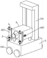
Fig. 1 is a perspective view of a side grinding device for processing a plate according to an embodiment of the present invention;
FIG. 2 is a schematic view of the structure at A in FIG. 1;
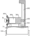
FIG. 3 is a front sectional view of a side grinding device for processing a plate according to an embodiment of the present invention;
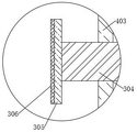
FIG. 4 is a schematic view of the structure of FIG. 3 at B;
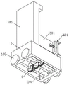
FIG. 5 is another perspective view of a side grinding device for processing a plate according to an embodiment of the present invention;
FIG. 6 is a schematic view of the structure of FIG. 5 at C;
fig. 7 is a side partial sectional view of a side grinding device for processing a plate according to an embodiment of the invention.
In the figure: 1. the grinding machine comprises a supporting base, 101, an auxiliary supporting frame, 102, a sliding groove, 103, an auxiliary supporting sliding block, 104, a rotating connecting rod, 105, a roller, 106, a supporting rod, 107, an auxiliary rotating turbine, 108, a driving turbine, 2, a moving mechanism, 201, a first motor, 202, a driving worm, 3, a grinding mechanism, 301, a supporting table, 302, an electric push rod, 303, a second motor, 304, a transmission shaft, 305, a supporting plate, 306, a grinding piece, 4, an auxiliary mechanism, 401, a fixed vertical plate, 402, a first threaded rod, 403, a supporting frame, 404, a second threaded rod, 405 and an auxiliary grinding block.
Detailed Description
The present invention will be described in detail below with reference to embodiments shown in the drawings. The embodiments are not intended to limit the present invention, and structural, methodological or functional changes made by those skilled in the art according to the embodiments are included in the scope of the present invention.
The invention discloses a side edge grinding device for processing plates, which is shown in a reference figure 1-7 and comprises: the grinding machine comprises a supporting base 1, a moving mechanism 2, a grinding mechanism 3 and an auxiliary mechanism 4.
Referring to fig. 1-3, an auxiliary support frame 101 is disposed on the support base 1, a sliding groove 102 is formed in the auxiliary support frame 101 to provide a space for the auxiliary support slider 103 to ascend and descend, and an auxiliary support slider 103 is disposed in the sliding groove 102 and used for assisting to fix the support table 301, so that the second motor 303 is prevented from driving the support table 301 to shake when in use, and therefore the stability of the device is increased, and the auxiliary mechanism 4 is prevented from shaking or shaking.
Referring to fig. 5-7, support and install a pair of swivelling joint pole 104 on the base 1 for drive gyro wheel 105 and rotate, thereby reach the effect that drives the whole device and remove, swivelling joint pole 104 runs through and supports the setting of base 1, easy to assemble gyro wheel 105, swivelling joint pole 104's both ends and support all are connected with fixing bearing between the base 1, can not receive the influence that supports base 1 when making swivelling joint pole 104 rotatory, thereby reduce the probability that unstable appears in the support base 1, improve the stability of device.
Referring to fig. 1 to 7, rollers 105 are installed at both ends of the rotary connecting rod 104 to drive the entire apparatus to move, so that the entire side of the plate can be conveniently polished without being pushed by a worker, thereby relieving the pressure of the worker.
Referring to fig. 6, a support rod 106 is disposed between the pair of rotating connecting rods 104 for supporting the auxiliary rotating turbine 107, so that the auxiliary rotating turbine 107 does not shake or fall off, the support rod 106 is mounted on the support base 1, and a fixing bearing is also connected between two ends of the support rod 106 and the support base 1, thereby facilitating rotation of the support rod 106.
Specifically, the supporting rod 106 is provided with an auxiliary rotating turbine 107 for driving one of the driving turbines 108 to rotate, so that the pair of driving turbines 108 can rotate synchronously, and the rotating directions of the pair of driving turbines 108 are the same, thereby facilitating the movement of the driving device.
Referring to fig. 5-7, a pair of rotating connecting rods 104 are each provided with a driving worm gear 108 for driving the pair of rotating connecting rods 104 to rotate, so as to drive the plurality of rollers 105 to rotate, thereby enabling the device to be movable, wherein one of the driving worm gears 108 is engaged with the auxiliary rotating worm gear 107, so that the auxiliary rotating worm gear 107 drives one of the driving worm gears 108 to rotate, and the rotation directions of the auxiliary rotating worm gear 107 and one of the driving worm gears 108 are opposite.
Referring to fig. 5-7, the moving mechanism 2 is disposed on the supporting base 1, and is moved by a driving unit, so as to conveniently polish the side of the plate, the moving mechanism 2 includes a first motor 201 for driving a driving worm 202 to rotate, so as to provide power for the movement of the whole device, and has a function of supporting the driving worm 202, the first motor 201 is mounted on the supporting base 1, and the first motor 201 is prevented from shaking or falling off.
The first motor 201 is connected with a driving worm 202 for driving the auxiliary rotating worm wheel 107 and one of the driving worm wheels 108 to rotate, and the driving worm 202 is meshed with the auxiliary rotating worm wheel 107 and one of the driving worm wheels 108, so that the auxiliary rotating worm wheel 107 and the driving worm wheel 108 are conveniently driven to rotate.
Referring to fig. 1-5, the polishing mechanism 3 is disposed between the supporting base 1 and the auxiliary supporting frame 101, and is configured to polish the side edge of the plate, the polishing mechanism 3 includes a supporting table 301, and is configured to support a pair of auxiliary mechanisms 4, and has an effect of driving the second motor 303 to go up and down, the supporting table 301 is fixedly connected to the auxiliary supporting slider 103, so that the auxiliary supporting slider 103 can assist in fixing the supporting table 301, and thus the stability of the supporting table 301 is improved, and after the second motor 303 is started, the supporting table 301 does not shake.
Referring to fig. 1 to 3, a plurality of electric push rods 302 are connected to the lower side of the supporting platform 301 for driving the supporting platform 301 to rise and fall, so as to drive the second motor 303 to rise and fall, and the plurality of electric push rods 302 are all installed and supported in the base 1, so that the electric push rods 302 do not shake and do not cut obliquely when extending.
Referring to fig. 1-3, a second motor 303 is mounted on the supporting table 301 for driving a transmission shaft 304 to rotate to provide power for polishing the side edge of the plate, and the transmission shaft 304 is connected to the second motor 303 for supporting the supporting disc 305 and the polishing element 306 and driving the supporting disc 305 and the polishing element 306 to rotate.
Referring to fig. 1 to 4, the other end of the transmission shaft 304 is connected to a supporting plate 305 for fixing a polishing member 306, so that the polishing member 306 does not fall off, and the supporting plate 305 is provided with the polishing member 306 for polishing the side edge of the plate, so that the plate has a good appearance and is convenient for subsequent processing.
Referring to fig. 1-2, a pair of auxiliary mechanisms 4 is installed on the supporting table 301 for assisting in polishing the side edge of the plate, each auxiliary mechanism 4 includes a fixed vertical plate 401 for supporting a first threaded rod 402, the fixed vertical plate 401 is fixedly connected to the supporting table 301 to prevent the fixed vertical plate 401 from falling off, the fixed vertical plate 401 is screwed with the first threaded rod 402, so that the first threaded rod 402 can drive the supporting frame 403 to move when rotating.
Wherein, the one end of first threaded rod 402 is connected with carriage 403 for support second threaded rod 404, supplementary sanding block 405 and drive second threaded rod 404, supplementary sanding block 405 and remove, and threaded connection has a pair of second threaded rod 404 on carriage 403 for support supplementary sanding block 405 and drive supplementary sanding block 405 and remove.
Referring to fig. 2, one end of the pair of second threaded rods 404 close to each other is connected with an auxiliary polishing block 405 for clamping on the edge of the side edge of the plate, so that when the device moves, the edge of the side edge can be polished, the polishing effect is improved, and the missing situation is avoided.
When the device is used specifically, a worker moves the device to one side of a plate, then starts the electric push rod 302, so that the electric push rod 302 can push the support table 301 to be lifted, so as to drive the second motor 303 to be lifted, when the grinding piece 306 is flush with the side edge of the plate, the electric push rod 302 is closed, then the device is pushed to enable the grinding piece 306 to be attached to the plate, and the device is made to be level with the plate, so that the situation of inclination can not occur during movement;
then, the first threaded rod 402 is rotated to enable the first threaded rod 402 to push the supporting frame 403 to be close to the plate, then the second threaded rod 404 is rotated to enable the auxiliary polishing block 405 to be attached to the plate, at this time, the second motor 303 is started to enable the second motor 303 to drive the transmission shaft 304 to rotate, so that the supporting plate 305 and the polishing piece 306 are driven to rotate, and the polishing effect can be achieved when the polishing piece 306 rotates;
the first motor 201 is started while the second motor 303 is started, so that the first motor 201 can drive the driving worm 202 to rotate, the driving worm 202 can drive the auxiliary rotating worm wheel 107 and one of the driving worm wheels 108 to rotate, the auxiliary rotating worm wheel 107 can drive the other driving worm wheel 108 to rotate, and therefore the pair of driving worm wheels 108 synchronously rotate and rotate in the same direction, the pair of driving worm wheels 108 can drive the pair of rotating connecting rods 104 to rotate, so that the plurality of rollers 105 are driven to rotate, the whole device is driven to move, when the device moves, the grinding piece 306 can grind the side edge of the plate, and the auxiliary grinding block 405 can assist in grinding the corner of the side edge.
It will be evident to those skilled in the art that the invention is not limited to the details of the foregoing illustrative embodiments, and that the present invention may be embodied in other specific forms without departing from the spirit or essential attributes thereof. The present embodiments are therefore to be considered in all respects as illustrative and not restrictive, the scope of the invention being indicated by the appended claims rather than by the foregoing description, and all changes which come within the meaning and range of equivalency of the claims are therefore intended to be embraced therein. Any reference sign in a claim should not be construed as limiting the claim concerned.
Furthermore, it should be understood that although the present description refers to embodiments, not every embodiment may contain only a single embodiment, and such description is for clarity only, and those skilled in the art should integrate the description, and the embodiments may be combined as appropriate to form other embodiments understood by those skilled in the art.
Claims (7)
Priority Applications (1)
| Application Number | Priority Date | Filing Date | Title |
|---|---|---|---|
| CN202210090416.1A CN114102316B (en) | 2022-01-26 | 2022-01-26 | A side grinding device for sheet metal processing |
Applications Claiming Priority (1)
| Application Number | Priority Date | Filing Date | Title |
|---|---|---|---|
| CN202210090416.1A CN114102316B (en) | 2022-01-26 | 2022-01-26 | A side grinding device for sheet metal processing |
Publications (2)
| Publication Number | Publication Date |
|---|---|
| CN114102316A true CN114102316A (en) | 2022-03-01 |
| CN114102316B CN114102316B (en) | 2022-05-17 |
Family
ID=80361420
Family Applications (1)
| Application Number | Title | Priority Date | Filing Date |
|---|---|---|---|
| CN202210090416.1A Withdrawn - After Issue CN114102316B (en) | 2022-01-26 | 2022-01-26 | A side grinding device for sheet metal processing |
Country Status (1)
| Country | Link |
|---|---|
| CN (1) | CN114102316B (en) |
Citations (7)
| Publication number | Priority date | Publication date | Assignee | Title |
|---|---|---|---|---|
| CN208759197U (en) * | 2018-07-20 | 2019-04-19 | 南京浦江电子有限公司 | Cylinder manifold edge grinding apparatus |
| CN109834541A (en) * | 2018-12-18 | 2019-06-04 | 天津市众联铝业有限公司 | A kind of flash eliminating equipment for aluminum profile processing |
| CN110977659A (en) * | 2019-12-25 | 2020-04-10 | 南京力聚精密锻造有限公司 | Continuous automatic grinding machine and grinding processing technology thereof |
| CN210818824U (en) * | 2019-10-25 | 2020-06-23 | 天津时弘科技有限公司 | Flush device for end face of water filtering pipe |
| CN211760352U (en) * | 2019-12-24 | 2020-10-27 | 上杭县康易达机械设备有限公司 | Plate trimming device |
| CN213351823U (en) * | 2020-10-19 | 2021-06-04 | 无锡布努曼科技有限公司 | Photovoltaic panel processing equipment assembly for solar energy |
| CN113635145A (en) * | 2021-10-12 | 2021-11-12 | 南通兴东叶片科技有限公司 | Surface treatment equipment and method for turbine stationary blade |
-
2022
- 2022-01-26 CN CN202210090416.1A patent/CN114102316B/en not_active Withdrawn - After Issue
Patent Citations (7)
| Publication number | Priority date | Publication date | Assignee | Title |
|---|---|---|---|---|
| CN208759197U (en) * | 2018-07-20 | 2019-04-19 | 南京浦江电子有限公司 | Cylinder manifold edge grinding apparatus |
| CN109834541A (en) * | 2018-12-18 | 2019-06-04 | 天津市众联铝业有限公司 | A kind of flash eliminating equipment for aluminum profile processing |
| CN210818824U (en) * | 2019-10-25 | 2020-06-23 | 天津时弘科技有限公司 | Flush device for end face of water filtering pipe |
| CN211760352U (en) * | 2019-12-24 | 2020-10-27 | 上杭县康易达机械设备有限公司 | Plate trimming device |
| CN110977659A (en) * | 2019-12-25 | 2020-04-10 | 南京力聚精密锻造有限公司 | Continuous automatic grinding machine and grinding processing technology thereof |
| CN213351823U (en) * | 2020-10-19 | 2021-06-04 | 无锡布努曼科技有限公司 | Photovoltaic panel processing equipment assembly for solar energy |
| CN113635145A (en) * | 2021-10-12 | 2021-11-12 | 南通兴东叶片科技有限公司 | Surface treatment equipment and method for turbine stationary blade |
Also Published As
| Publication number | Publication date |
|---|---|
| CN114102316B (en) | 2022-05-17 |
Similar Documents
| Publication | Publication Date | Title |
|---|---|---|
| CN211759790U (en) | Various steel sheet cutting integration mechanism of polishing | |
| CN212072275U (en) | A new type of trimming machine | |
| CN115781470B (en) | A even burnishing device of roughness for plastic-aluminum board processing usefulness | |
| CN115570465A (en) | A kind of edge grinding equipment for building environmental protection board | |
| CN222493042U (en) | Angle steel cutting equipment | |
| CN211163168U (en) | Edge of a knife grinding device for riving knife | |
| CN210480310U (en) | Automatic paper feeding frame for abrasive paper | |
| CN218801109U (en) | Plate processing device | |
| CN114102316B (en) | A side grinding device for sheet metal processing | |
| CN219358944U (en) | A plate grinding device | |
| CN217915417U (en) | A robot base | |
| CN201271834Y (en) | Polishing device with compensation mechanism | |
| CN214393515U (en) | A polishing fixture for tool production and processing | |
| CN215616960U (en) | Supplementary trimming device of wall crown | |
| CN109571034A (en) | A kind of segmentation for air equipment plate, which is repaired, cuts equipment and its working method | |
| CN118595999B (en) | Polishing equipment of polishing that support processing was used | |
| CN212191463U (en) | Machining equipment for steel structure treatment | |
| CN220806673U (en) | Door and window glass edge processing polishing's equipment of polishing | |
| CN220561104U (en) | Edging device is used in panel processing | |
| CN205184515U (en) | Elevating system of glass edging machine reaches and compresses tightly elevating system | |
| CN221871363U (en) | Leveling device for building curtain wall production | |
| CN221735687U (en) | Edge grinding device with protective structure | |
| CN213196135U (en) | A multifunctional laser machine carrying platform | |
| CN217413580U (en) | Burnishing device that curtain decorative board was used | |
| CN216912869U (en) | Screw dismounting machine for dismounting computer case |
Legal Events
| Date | Code | Title | Description |
|---|---|---|---|
| PB01 | Publication | ||
| PB01 | Publication | ||
| SE01 | Entry into force of request for substantive examination | ||
| SE01 | Entry into force of request for substantive examination | ||
| GR01 | Patent grant | ||
| GR01 | Patent grant | ||
| AV01 | Patent right actively abandoned | ||
| AV01 | Patent right actively abandoned | ||
| AV01 | Patent right actively abandoned |
Granted publication date: 20220517 Effective date of abandoning: 20250704 |
|
| AV01 | Patent right actively abandoned |
Granted publication date: 20220517 Effective date of abandoning: 20250704 |