CN114057026A - Yarn arranging device for spinning cotton yarn - Google Patents
Yarn arranging device for spinning cotton yarn Download PDFInfo
- Publication number
- CN114057026A CN114057026A CN202111273746.6A CN202111273746A CN114057026A CN 114057026 A CN114057026 A CN 114057026A CN 202111273746 A CN202111273746 A CN 202111273746A CN 114057026 A CN114057026 A CN 114057026A
- Authority
- CN
- China
- Prior art keywords
- yarn
- fixedly connected
- dust removal
- fixed
- main body
- Prior art date
- Legal status (The legal status is an assumption and is not a legal conclusion. Google has not performed a legal analysis and makes no representation as to the accuracy of the status listed.)
- Withdrawn
Links
- 238000009987 spinning Methods 0.000 title claims abstract description 23
- 229920000742 Cotton Polymers 0.000 title claims abstract description 20
- 239000000428 dust Substances 0.000 claims abstract description 52
- 238000004804 winding Methods 0.000 claims abstract description 9
- 239000002699 waste material Substances 0.000 claims description 7
- 238000005096 rolling process Methods 0.000 claims description 5
- 239000003292 glue Substances 0.000 claims description 3
- 238000011084 recovery Methods 0.000 claims description 3
- 230000008878 coupling Effects 0.000 claims 1
- 238000010168 coupling process Methods 0.000 claims 1
- 238000005859 coupling reaction Methods 0.000 claims 1
- 238000000034 method Methods 0.000 abstract description 8
- 230000000694 effects Effects 0.000 abstract description 6
- 230000003068 static effect Effects 0.000 abstract description 6
- 244000309464 bull Species 0.000 abstract description 4
- 210000001520 comb Anatomy 0.000 abstract description 3
- 238000010030 laminating Methods 0.000 abstract description 2
- 238000004064 recycling Methods 0.000 description 5
- 239000002994 raw material Substances 0.000 description 4
- 244000025254 Cannabis sativa Species 0.000 description 2
- 230000007547 defect Effects 0.000 description 2
- 230000005611 electricity Effects 0.000 description 2
- 239000004744 fabric Substances 0.000 description 2
- 238000003672 processing method Methods 0.000 description 2
- 239000000126 substance Substances 0.000 description 2
- 235000012766 Cannabis sativa ssp. sativa var. sativa Nutrition 0.000 description 1
- 235000012765 Cannabis sativa ssp. sativa var. spontanea Nutrition 0.000 description 1
- 241001465754 Metazoa Species 0.000 description 1
- 230000004075 alteration Effects 0.000 description 1
- 239000011324 bead Substances 0.000 description 1
- 230000009286 beneficial effect Effects 0.000 description 1
- 235000009120 camo Nutrition 0.000 description 1
- 238000003763 carbonization Methods 0.000 description 1
- 235000005607 chanvre indien Nutrition 0.000 description 1
- 239000000835 fiber Substances 0.000 description 1
- 239000011487 hemp Substances 0.000 description 1
- 239000012535 impurity Substances 0.000 description 1
- 238000000053 physical method Methods 0.000 description 1
- 238000002360 preparation method Methods 0.000 description 1
- 238000007670 refining Methods 0.000 description 1
- 238000001179 sorption measurement Methods 0.000 description 1
- 238000006467 substitution reaction Methods 0.000 description 1
- 235000013311 vegetables Nutrition 0.000 description 1
- 238000005406 washing Methods 0.000 description 1
- 210000002268 wool Anatomy 0.000 description 1
Images




Classifications
-
- B—PERFORMING OPERATIONS; TRANSPORTING
- B65—CONVEYING; PACKING; STORING; HANDLING THIN OR FILAMENTARY MATERIAL
- B65H—HANDLING THIN OR FILAMENTARY MATERIAL, e.g. SHEETS, WEBS, CABLES
- B65H54/00—Winding, coiling, or depositing filamentary material
- B65H54/70—Other constructional features of yarn-winding machines
- B65H54/702—Arrangements for confining or removing dust
-
- B—PERFORMING OPERATIONS; TRANSPORTING
- B65—CONVEYING; PACKING; STORING; HANDLING THIN OR FILAMENTARY MATERIAL
- B65H—HANDLING THIN OR FILAMENTARY MATERIAL, e.g. SHEETS, WEBS, CABLES
- B65H54/00—Winding, coiling, or depositing filamentary material
- B65H54/02—Winding and traversing material on to reels, bobbins, tubes, or like package cores or formers
- B65H54/28—Traversing devices; Package-shaping arrangements
-
- B—PERFORMING OPERATIONS; TRANSPORTING
- B65—CONVEYING; PACKING; STORING; HANDLING THIN OR FILAMENTARY MATERIAL
- B65H—HANDLING THIN OR FILAMENTARY MATERIAL, e.g. SHEETS, WEBS, CABLES
- B65H57/00—Guides for filamentary materials; Supports therefor
- B65H57/14—Pulleys, rollers, or rotary bars
-
- B—PERFORMING OPERATIONS; TRANSPORTING
- B65—CONVEYING; PACKING; STORING; HANDLING THIN OR FILAMENTARY MATERIAL
- B65H—HANDLING THIN OR FILAMENTARY MATERIAL, e.g. SHEETS, WEBS, CABLES
- B65H59/00—Adjusting or controlling tension in filamentary material, e.g. for preventing snarling; Applications of tension indicators
- B65H59/10—Adjusting or controlling tension in filamentary material, e.g. for preventing snarling; Applications of tension indicators by devices acting on running material and not associated with supply or take-up devices
-
- H—ELECTRICITY
- H05—ELECTRIC TECHNIQUES NOT OTHERWISE PROVIDED FOR
- H05F—STATIC ELECTRICITY; NATURALLY-OCCURRING ELECTRICITY
- H05F3/00—Carrying-off electrostatic charges
Landscapes
- Engineering & Computer Science (AREA)
- Textile Engineering (AREA)
- Spinning Or Twisting Of Yarns (AREA)
Abstract
The invention relates to a yarn arranging device for spinning cotton yarns, which belongs to the technical field of yarn arranging devices and comprises a base main body, wherein a yarn arranging mechanism and a dust removing mechanism are arranged on the base main body. Close the connection through going into line mouth screw thread soon and close the lid soon, conveniently carry out first step dust removal processing to the yarn, close the lid soon in going into line mouth screw thread simultaneously and close the connection, conveniently close the change of lid soon, through the bottom laminating of yarn and first runner, exert pressure to the yarn through the power that first tight spring in top given first runner and guarantee that the yarn keeps straight in reason line in-process. Drive the bull stick through second driving motor and rotate, the activity of control activity ring makes connecting rod reciprocating motion, drives reason spool reciprocating motion, combs the yarn, avoids the yarn phenomenon such as knot appear with receiving the winding in-process of line roller, influences the quality of yarn, through set up wet sponge on first live-rollers and second live-rollers, conveniently eliminates the static on the yarn.
Description
Technical Field
The invention belongs to the technical field of yarn arranging devices, and relates to a yarn arranging device for spinning cotton yarns.
Background
Spinning is the twisting of many animal and vegetable fibres together by means of a spinning machine into threads or yarns which can be used to weave into cloth. During the spinning process, the defects are cleaned, i.e. the raw material is subjected to primary processing, which is also called the preparation of the spinning raw material. The types of raw materials are different, the types and properties of impurities are different, and the processing methods and processes are also different. The primary processing methods of the raw materials mainly include physical methods (such as cotton ginning), chemical methods (such as degumming of hemp and refining of spun silk) and physical and chemical combined methods (such as washing of wool and grass removal and carbonization).
The existing yarn arranging device has certain defect in design, firstly, yarns tend to attract a lot of dust due to static generated by friction of fibers in the yarn twisting process, the product quality is influenced, secondly, when winding rollers wind the yarns, the winding is uneven and the yarns are wound together easily, and the yarns are knotted when the yarns are woven in the later period, so that the yarn arranging device for spinning cotton yarns is designed to solve the problems.
Disclosure of Invention
The invention aims to provide a yarn arranging device for spinning cotton yarns, which has the characteristics of avoiding static electricity generated by the yarns, avoiding dust adsorption and avoiding yarn knotting.
The purpose of the invention can be realized by the following technical scheme:
a reason traditional thread binding putting for cotton system yarn spinning processing, including the base main part, be equipped with reason line mechanism and dust removal mechanism in the base main part, go back fixedly connected with fixed bolster in the base main part, the inside of fixed bolster is equipped with admission machine and constructs, be connected with first live-rollers and second live-rollers through the support rotation respectively in the base main part, first live-rollers and second live-rollers are located between reason line mechanism and the fixed bolster.
According to the preferable technical scheme of the yarn arranging device for spinning cotton yarns, the dust removing mechanism comprises a dust removing shell, a wire outlet is formed in one side, facing the yarn arranging mechanism, of the dust removing shell, a wire inlet is formed in one side, different from the yarn arranging mechanism, of the dust removing shell, dust removing rollers are symmetrically and rotatably connected to the interior of the dust removing shell, one end of each dust removing roller extends into the inner wall of the dust removing shell and is fixedly connected with a gear, the two gears are meshed, a first driving motor is mounted on one side of the dust removing shell through a support, and an output shaft of the first driving motor is fixedly connected with one dust removing roller. The thread-in opening is screwed with a screwing cover, the inner wall of the screwing cover is bonded with sponge through glue, and one side of the screwing cover facing the outside is symmetrically and fixedly connected with a dust removal head. The base main part is provided with a sunken part, a waste recycling bin is movably connected in the sunken part, and the waste recycling bin is positioned below the wire inlet.
According to the preferable technical scheme of the yarn arranging device for spinning cotton yarns, the yarn arranging mechanism comprises two fixed stand columns, the fixed stand columns are symmetrically and fixedly connected to a base main body, cavities are formed in the fixed stand columns, fixed rods are fixedly connected inside the cavities, sliding rods are movably connected between the two fixed stand columns, two ends of each sliding rod are respectively connected with the corresponding fixed rods in a sliding mode, first jacking springs are fixedly connected between the sliding rods and the top ends of the cavities, the first jacking springs are sleeved on the fixed rods, and first rotating wheels are rotatably connected to the sliding rods.
According to the preferable technical scheme of the yarn arranging device for spinning cotton yarns, the fixed support is internally and rotatably connected with the yarn collecting roller, the yarn collecting mechanism comprises a movable plate main body, the movable plate main body is located above the yarn collecting roller, one end of the movable plate main body is fixedly connected with the expanded movable plate, one side of the expanded movable plate is provided with the second driving motor through the support, an output shaft of the second driving motor penetrates through the expanded movable plate and is fixedly connected with the rotating rod, one end, far away from the output shaft of the second driving motor, of the rotating rod is fixedly connected with the connecting bulge, the movable plate main body is internally and slidably connected with the sliding block, the connecting rod is fixedly connected onto the sliding block, one end, different from the sliding block, of the connecting rod is fixedly connected with the movable ring, and the connecting bulge slides inside the movable ring. The bottom fixedly connected with fixed connection piece of sliding block, fixed connection piece downwardly extending to the outside of fly leaf main part and the first connecting plate of fixedly connected with, the below of first connecting plate is equipped with the second connecting plate, the bottom of second connecting plate is equipped with roll pearl and reason line pipe, it is located between the roll pearl to manage the line pipe, symmetry fixedly connected with second top tight spring between second connecting plate and the first connecting plate. The top fixedly connected with electric putter of fixed bolster, electric putter's expansion end and the top fixed connection of fly leaf main part, still symmetry fixedly connected with telescopic link between fly leaf main part and the fixed bolster.
The invention has the beneficial effects that:
(1) close the connection through going into line mouth screw thread soon and close the lid soon, conveniently carry out first step dust removal processing to the yarn, close the lid soon in going into line mouth screw thread simultaneously and close the connection, conveniently close the change of lid soon, through the bottom laminating of yarn and first runner, exert pressure to the yarn through the power that first tight spring in top given first runner and guarantee that the yarn keeps straight in reason line in-process.
(2) Drive the bull stick through second driving motor and rotate, the activity of control activity ring makes connecting rod reciprocating motion, drives reason spool reciprocating motion, combs the yarn, avoids the yarn phenomenon such as knot appear with receiving the winding in-process of line roller, influences the quality of yarn, through set up wet sponge on first live-rollers and second live-rollers, conveniently eliminates the static on the yarn.
Drawings
In order to facilitate understanding for those skilled in the art, the present invention will be further described with reference to the accompanying drawings.
FIG. 1 is a schematic structural view of the present invention;
FIG. 2 is a schematic elevational cross-sectional configuration of the present invention;
FIG. 3 is a schematic view showing the internal structure of the dust-removing casing according to the present invention;
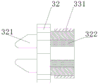
FIG. 4 is a schematic view of the internal structure of the screw closure of the present invention;
FIG. 5 is a schematic view of the internal structure of the wire management mechanism of the present invention;
FIG. 6 is a schematic view of the internal structure of the take-up mechanism of the present invention;
FIG. 7 is an enlarged schematic view of the structure at A in FIG. 6;
in the figure: 1. a base body; 2. a wire arrangement mechanism; 21. fixing the upright post; 22. a slide bar; 23. a first urging spring; 24. a cavity; 25. a first runner; 26. fixing the rod; 3. a dust removal mechanism; 31. a first drive motor; 32. screwing the cover; 321. a dust removal head; 322. a sponge; 33. a dust removal housing; 331. a wire inlet; 332. an outlet; 34. a dust removal roller; 35. a gear; 4. a first rotating roller; 5. a second rotating roller; 6. a take-up mechanism; 61. a second drive motor; 62. fixing a bracket; 63. a wire take-up roller; 64. a slider; 641. fixing a connecting block; 642. a first connecting plate; 643. a second urging spring; 644. a second connecting plate; 645. rolling the beads; 646. managing the tubes; 65. an electric push rod; 66. a movable plate main body; 661. expanding the movable plate; 67. a movable ring; 671. a connecting rod; 68. a rotating rod; 681. a connecting projection; 7. a waste recycling bin.
Detailed Description
The technical solutions of the present invention will be described clearly and completely with reference to the following embodiments, and it should be understood that the described embodiments are only a part of the embodiments of the present invention, and not all of the embodiments. All other embodiments, which can be derived by a person skilled in the art from the embodiments given herein without making any creative effort, shall fall within the protection scope of the present invention.
Referring to fig. 1-7, the yarn arranging device for spinning cotton yarn includes a base main body 1, a yarn arranging mechanism 2 and a dust removing mechanism 3 are disposed on the base main body 1, a fixing bracket 62 is further fixedly connected to the base main body 1, a yarn collecting mechanism 6 is disposed inside the fixing bracket 62, a first rotating roller 4 and a second rotating roller 5 are rotatably connected to the base main body 1 through brackets, and the first rotating roller 4 and the second rotating roller 5 are located between the yarn arranging mechanism 2 and the fixing bracket 62.
In this embodiment, guarantee through reason line mechanism 2 that the yarn is in the state of stretching straight all the time, clear away the dust on yarn surface through dust removal mechanism 3, clear away the static on yarn surface through first live-rollers 4 and second live-rollers 5, guarantee the recovery of yarn through admission machine 6, avoid the winding.
Specifically, dust removal mechanism 3 includes dust removal shell 33, outlet 332 has been seted up towards one side of reason line mechanism 2 to dust removal shell 33, dust removal shell 33 is different from one side of reason line mechanism 2 and has been seted up into line mouth 331, the inside symmetry of dust removal shell 33 is rotated and is connected with dust removal roller 34, the one end of dust removal roller 34 extends to the inner wall of dust removal shell 33 in and fixedly connected with gear 35, two the gear 35 meshing, there is first driving motor 31 one side of dust removal shell 33 through the support mounting, first driving motor 31's output shaft and one of them dust removal roller 34 fixed connection. The thread inlet 331 is connected with a screwing cover 32 in a screwing manner through threads, the inner wall of the screwing cover 32 is adhered with a sponge 322 through glue, and one side of the screwing cover 32 facing to the outside is symmetrically and fixedly connected with a dust removing head 321. The base main body 1 is provided with a concave part, a waste recycling bin 7 is movably connected in the concave part, and the waste recycling bin 7 is located below the wire inlet 331.
In this embodiment, the screw cap 32 is screwed with the thread inlet 331 to facilitate the removal and replacement of the screw cap 32, the yarn is first processed through the dust removing head 321 on the surface of the yarn, and then is wiped through the sponge 322 after the processing is finished, and then is processed for the second time through the dust removing roller 34.
Specifically, reason line mechanism 2 includes two fixed posts 21, fixed post 21 symmetry fixed connection is in base main part 1, cavity 24 has been seted up on the fixed post 21, the inside fixedly connected with dead lever 26 of cavity 24, two swing joint has slide bar 22 between the fixed post 21, and the both ends of slide bar 22 respectively with the dead lever 26 sliding connection who corresponds the limit, the first tight spring 23 in top of fixedly connected with between the top of slide bar 22 and cavity 24, and first tight spring 23 in top cup joints on dead lever 26, it is connected with first runner 25 to rotate on the slide bar 22.
In this embodiment, when the yarn passes through the first rotating wheel 25, the sliding rod 22 moves upward along the fixed rod 26, and the first tightening spring 23 contracts to ensure that the yarn is in a straightened state.
Specifically, the inside of fixed bolster 62 is rotated and is connected with receipts line roller 63, admission machine 6 includes fly leaf main part 66, fly leaf main part 66 is located the top of receiving line roller 63, the one end fixedly connected with of fly leaf main part 66 extends fly leaf 661, extend one side of fly leaf 661 and have second driving motor 61 through the support mounting, the output shaft of second driving motor 61 runs through and extends fly leaf 661 and fixedly connected with bull stick 68, the one end fixedly connected with of second driving motor 61 output shaft connects protruding 681 is kept away from to bull stick 68, the inside sliding connection of fly leaf main part 66 has sliding block 64, fixedly connected with connecting rod 671 on the sliding block 64, be different from the one end fixedly connected with activity ring 67 of sliding block 64 on the connecting rod 671, connect protruding 681 and slide in the inside of activity ring 67. A fixed connecting block 641 is fixedly connected to the bottom end of the sliding block 64, the fixed connecting block 641 extends downward to the outside of the movable plate main body 66 and is fixedly connected with a first connecting plate 642, a second connecting plate 644 is arranged below the first connecting plate 642, a rolling ball 645 and a wire arranging pipe 646 are arranged at the bottom end of the second connecting plate 644, the wire arranging pipe 646 is located between the rolling balls 645, and a second tightening spring 643 is symmetrically and fixedly connected between the second connecting plate 644 and the first connecting plate 642. The top end fixedly connected with electric putter 65 of fixed bolster 62, the expansion end of electric putter 65 and the top end fixed connection of fly leaf main part 66, still symmetry fixedly connected with telescopic link between fly leaf main part 66 and the fixed bolster 62.
In this embodiment, the electric push rod 65 is started, one end of the yarn arranging pipe 646 is placed on the yarn receiving roller 63, the second driving motor 61 is started to drive the rotating rod 68 to rotate, the connecting protrusion 681 moves in the movable ring 67, and the connecting rod 671 drives the sliding block 64 to slide, so that the yarn arranging pipe 646 combs yarns, and the yarns are prevented from being wound and knotted.
When the invention is used:
the yarn passes through the screwing cover 32, is arranged at the bottom layer of the first rotating wheel 25, is arranged at the bottom layer of the second rotating roller 5 after passing through the surface of the first rotating roller 4, is finally wound on the take-up roller 63, is subjected to first-step treatment on dust on the surface of the yarn through the dust removal head 321, is wiped through the sponge 322 after being treated, is subjected to second-step treatment through the dust removal roller 34, when the yarn passes through the first rotating wheel 25, the sliding rod 22 moves upwards along the fixed rod 26, the first tightening spring 23 contracts to ensure that the yarn is in a straightening state, the yarn passes through the first rotating roller 4, wet sponge is arranged on the first rotating roller 4 to eliminate static electricity of the yarn, the yarn is wiped through a dry cloth piece on the second rotating roller 5 after being eliminated, the electric push rod 65 is started, one end of the yarn treatment pipe 646 is placed on the take-up roller 63, the second driving motor 61 is started to drive the rotating rod 68 to rotate, the connecting protrusion 681 is enabled to move in the movable ring 67, the connecting rod 671 drives the sliding block 64 to slide, the yarn arranging pipe 646 is enabled to comb the yarns, and the yarns are prevented from being wound and knotted.
Although the present invention has been described with reference to the preferred embodiments, it should be understood that various changes, substitutions and alterations can be made herein without departing from the spirit and scope of the invention as defined by the appended claims.
Claims (8)
1. A reason traditional thread binding putting for cotton system yarn spinning processing, including base main part (1), its characterized in that: be equipped with reason line mechanism (2) and dust removal mechanism (3) on base main part (1), still fixedly connected with fixed bolster (62) on base main part (1), the inside of fixed bolster (62) is equipped with admission machine and constructs (6), be connected with first live-rollers (4) and second live-rollers (5) through the rotate bracket respectively on base main part (1), first live-rollers (4) and second live-rollers (5) are located between reason line mechanism (2) and fixed bolster (62).
2. The yarn arranging device for cotton yarn spinning process according to claim 1, characterized in that: dust removal mechanism (3) are including dust removal shell (33), outlet (332) have been seted up towards one side of reason line mechanism (2) in dust removal shell (33), line inlet (331) have been seted up in one side that dust removal shell (33) are different from reason line mechanism (2), the inside symmetry of dust removal shell (33) is rotated and is connected with dust removal roller (34), the one end of dust removal roller (34) extends to in the inner wall of dust removal shell (33) and fixedly connected with gear (35), two gear (35) meshing, there is first driving motor (31) one side of dust removal shell (33) through the support mounting, the output shaft and one of them dust removal roller (34) fixed connection of first driving motor (31).
3. The yarn arranging device for cotton yarn spinning process according to claim 2, characterized in that: the wire inlet (331) is connected with a screwing cover (32) in a screwing manner through threads, a sponge (322) is adhered to the inner wall of the screwing cover (32) through glue, and one side of the screwing cover (32) facing to the outside is symmetrically and fixedly connected with a dust removing head (321).
4. The yarn arranging device for cotton yarn spinning process according to claim 3, characterized in that: the base main body (1) is provided with a concave part, a waste recovery barrel (7) is movably connected in the concave part, and the waste recovery barrel (7) is positioned below the wire inlet (331).
5. The yarn arranging device for cotton yarn spinning process according to claim 1, characterized in that: reason line mechanism (2) include two fixed posts (21), fixed post (21) symmetry fixed connection is on base main part (1), cavity (24) have been seted up on fixed post (21), inside fixedly connected with dead lever (26) of cavity (24), two swing joint has slide bar (22) between fixed post (21), and the both ends of slide bar (22) respectively with dead lever (26) sliding connection who corresponds the limit, the tight spring in first top (23) of fixedly connected with between the top of slide bar (22) and cavity (24), and the tight spring in first top (23) cup joints on dead lever (26), it is connected with first runner (25) to rotate on slide bar (22).
6. The yarn arranging device for cotton yarn spinning process according to claim 1, characterized in that: the wire winding mechanism comprises a fixed support (62), a wire winding roller (63) is rotatably connected to the inside of the fixed support (62), a wire winding mechanism (6) comprises a movable plate main body (66), the movable plate main body (66) is located above the wire winding roller (63), an expanding movable plate (661) is fixedly connected to one end of the movable plate main body (66), a second driving motor (61) is installed on one side of the expanding movable plate (661) through a support, an output shaft of the second driving motor (61) penetrates through the expanding movable plate (661) and is fixedly connected with a rotating rod (68), one end of the rotating rod (68) far away from the output shaft of the second driving motor (61) is fixedly connected with a connecting bulge (681), a sliding block (64) is slidably connected to the inside of the movable plate main body (66), a connecting rod (671) is fixedly connected to the sliding block (64), and a movable ring (67) different from the sliding block (64) is fixedly connected to the connecting rod (671), the coupling projection (681) slides inside the movable ring (67).
7. The yarn arranging device for cotton yarn spinning process according to claim 6, characterized in that: the bottom end of the sliding block (64) is fixedly connected with a fixed connecting block (641), the fixed connecting block (641) extends downwards to the outside of the movable plate main body (66) and is fixedly connected with a first connecting plate (642), a second connecting plate (644) is arranged below the first connecting plate (642), the bottom end of the second connecting plate (644) is provided with rolling balls (645) and a wire arranging pipe (646), the wire arranging pipe (646) is located between the rolling balls (645), and second jacking springs (643) are symmetrically and fixedly connected between the second connecting plate (644) and the first connecting plate (642).
8. The yarn arranging device for cotton yarn spinning process according to claim 6, characterized in that: the top fixedly connected with electric putter (65) of fixed bolster (62), the expansion end of electric putter (65) and the top fixed connection of fly leaf main part (66), still symmetry fixedly connected with telescopic link between fly leaf main part (66) and fixed bolster (62).
Priority Applications (1)
| Application Number | Priority Date | Filing Date | Title |
|---|---|---|---|
| CN202111273746.6A CN114057026A (en) | 2021-10-29 | 2021-10-29 | Yarn arranging device for spinning cotton yarn |
Applications Claiming Priority (1)
| Application Number | Priority Date | Filing Date | Title |
|---|---|---|---|
| CN202111273746.6A CN114057026A (en) | 2021-10-29 | 2021-10-29 | Yarn arranging device for spinning cotton yarn |
Publications (1)
| Publication Number | Publication Date |
|---|---|
| CN114057026A true CN114057026A (en) | 2022-02-18 |
Family
ID=80236091
Family Applications (1)
| Application Number | Title | Priority Date | Filing Date |
|---|---|---|---|
| CN202111273746.6A Withdrawn CN114057026A (en) | 2021-10-29 | 2021-10-29 | Yarn arranging device for spinning cotton yarn |
Country Status (1)
| Country | Link |
|---|---|
| CN (1) | CN114057026A (en) |
Citations (12)
| Publication number | Priority date | Publication date | Assignee | Title |
|---|---|---|---|---|
| CN108178025A (en) * | 2017-12-28 | 2018-06-19 | 苏州朦井纺织科技有限公司 | A kind of weaving winding roller |
| CN109305606A (en) * | 2018-11-07 | 2019-02-05 | 湖州萌星服饰有限公司 | Easy-to-use automatic winder |
| CN208516658U (en) * | 2018-07-26 | 2019-02-19 | 四川金天亿管业有限公司 | Tension-adjusting gear is used in a kind of processing of steel wire mesh frame polyethylene compound pipe |
| CN210684268U (en) * | 2019-07-10 | 2020-06-05 | 吴江市平望漂染厂有限公司 | Clean production dust collector is used in weaving |
| CN211112399U (en) * | 2019-09-26 | 2020-07-28 | 苏州生生源纱业有限公司 | Spinning machine's dust collector |
| DE212020000201U1 (en) * | 2020-09-17 | 2020-10-08 | Suzhou Mochou Culture Technology Co., Ltd. | A winding structure for textile processing with the function of ironing and dust removal |
| CN212741642U (en) * | 2020-06-02 | 2021-03-19 | 晋江市达丽弹性织造有限公司 | Yarn cleaning device for bobbin winder |
| CN213079375U (en) * | 2020-08-18 | 2021-04-30 | 太湖联邦新材料科技有限公司 | A dust removal device for polyimide film |
| CN213172764U (en) * | 2020-07-27 | 2021-05-11 | 桐乡伟丰毛织有限责任公司 | Improve warper of warp quality |
| CN213558880U (en) * | 2020-10-21 | 2021-06-29 | 安徽富日智能装备有限公司 | Dust collector is used in coating machine processing |
| CN214027782U (en) * | 2020-07-03 | 2021-08-24 | 保山市弘泰包装印刷有限公司 | A dust collector for printing production |
| CN214400847U (en) * | 2020-12-02 | 2021-10-15 | 响水县天盈纺织有限公司 | Rotor spinning machine with dust removal effect |
-
2021
- 2021-10-29 CN CN202111273746.6A patent/CN114057026A/en not_active Withdrawn
Patent Citations (12)
| Publication number | Priority date | Publication date | Assignee | Title |
|---|---|---|---|---|
| CN108178025A (en) * | 2017-12-28 | 2018-06-19 | 苏州朦井纺织科技有限公司 | A kind of weaving winding roller |
| CN208516658U (en) * | 2018-07-26 | 2019-02-19 | 四川金天亿管业有限公司 | Tension-adjusting gear is used in a kind of processing of steel wire mesh frame polyethylene compound pipe |
| CN109305606A (en) * | 2018-11-07 | 2019-02-05 | 湖州萌星服饰有限公司 | Easy-to-use automatic winder |
| CN210684268U (en) * | 2019-07-10 | 2020-06-05 | 吴江市平望漂染厂有限公司 | Clean production dust collector is used in weaving |
| CN211112399U (en) * | 2019-09-26 | 2020-07-28 | 苏州生生源纱业有限公司 | Spinning machine's dust collector |
| CN212741642U (en) * | 2020-06-02 | 2021-03-19 | 晋江市达丽弹性织造有限公司 | Yarn cleaning device for bobbin winder |
| CN214027782U (en) * | 2020-07-03 | 2021-08-24 | 保山市弘泰包装印刷有限公司 | A dust collector for printing production |
| CN213172764U (en) * | 2020-07-27 | 2021-05-11 | 桐乡伟丰毛织有限责任公司 | Improve warper of warp quality |
| CN213079375U (en) * | 2020-08-18 | 2021-04-30 | 太湖联邦新材料科技有限公司 | A dust removal device for polyimide film |
| DE212020000201U1 (en) * | 2020-09-17 | 2020-10-08 | Suzhou Mochou Culture Technology Co., Ltd. | A winding structure for textile processing with the function of ironing and dust removal |
| CN213558880U (en) * | 2020-10-21 | 2021-06-29 | 安徽富日智能装备有限公司 | Dust collector is used in coating machine processing |
| CN214400847U (en) * | 2020-12-02 | 2021-10-15 | 响水县天盈纺织有限公司 | Rotor spinning machine with dust removal effect |
Similar Documents
| Publication | Publication Date | Title |
|---|---|---|
| CN112249812A (en) | Yarn evenly winds package and puts with clearance function | |
| CN111364187A (en) | Textile material belt cleaning device of quick dehydration is used in weaving | |
| CN215947496U (en) | Polyester-viscose fabric twisting machine | |
| CN216473653U (en) | Twisting machine convenient to twisting is adjusted | |
| CN113445163B (en) | Intelligent spinning winding device | |
| CN212611061U (en) | Spinning frame for producing high-tenacity yarns | |
| CN113638084A (en) | A kind of production device of core-spun yarn | |
| CN118932557A (en) | A sewing thread twisting device | |
| CN116288839B (en) | Spinning equipment and spinning method for spandex blended yarn | |
| CN216550891U (en) | Spinning machine with cleaning function | |
| CN212387394U (en) | Automatic cloth rolling equipment for textile industry | |
| CN211625995U (en) | Dewatering device is used in cotton yarn production | |
| CN209529027U (en) | Safe dust-extraction unit for weft yarn channels | |
| CN218201524U (en) | Textile machine capable of preventing thread clusters from loosening | |
| CN209038747U (en) | A kind of good weaving loom bobbin winder device of dedusting anti-acoustic capability | |
| CN222795836U (en) | Spinning locomotive belly cleaning device | |
| CN222743771U (en) | Conveying mechanism for coated yarn production | |
| CN220867634U (en) | Warping machine for towel production | |
| CN218666485U (en) | Doffing device for roving frame | |
| CN213445565U (en) | A kind of cotton fiber automatic winding device | |
| CN220952498U (en) | Cloth wetting mechanism of textile machine | |
| CN114753036B (en) | Cotton yarn impurity removing device and method for twisting machine | |
| CN220412419U (en) | Double-yarn automatic winder for water-soluble yarns | |
| CN204803477U (en) | Take cleaner on fly frame of sprocket feed device | |
| CN222908209U (en) | A composite twisting device for rayon yarn |
Legal Events
| Date | Code | Title | Description |
|---|---|---|---|
| PB01 | Publication | ||
| PB01 | Publication | ||
| SE01 | Entry into force of request for substantive examination | ||
| SE01 | Entry into force of request for substantive examination | ||
| WW01 | Invention patent application withdrawn after publication | ||
| WW01 | Invention patent application withdrawn after publication |
Application publication date: 20220218 |