CN114054651B - Modularized device of plane precast pier reinforcement cage and rectangular reinforcement cage manufacturing method - Google Patents
Modularized device of plane precast pier reinforcement cage and rectangular reinforcement cage manufacturing method Download PDFInfo
- Publication number
- CN114054651B CN114054651B CN202111426315.9A CN202111426315A CN114054651B CN 114054651 B CN114054651 B CN 114054651B CN 202111426315 A CN202111426315 A CN 202111426315A CN 114054651 B CN114054651 B CN 114054651B
- Authority
- CN
- China
- Prior art keywords
- reinforcement cage
- rectangular
- threaded
- support rod
- bases
- Prior art date
- Legal status (The legal status is an assumption and is not a legal conclusion. Google has not performed a legal analysis and makes no representation as to the accuracy of the status listed.)
- Active
Links
Images




Classifications
-
- B—PERFORMING OPERATIONS; TRANSPORTING
- B21—MECHANICAL METAL-WORKING WITHOUT ESSENTIALLY REMOVING MATERIAL; PUNCHING METAL
- B21F—WORKING OR PROCESSING OF METAL WIRE
- B21F31/00—Making meshed-ring network from wire
-
- B—PERFORMING OPERATIONS; TRANSPORTING
- B21—MECHANICAL METAL-WORKING WITHOUT ESSENTIALLY REMOVING MATERIAL; PUNCHING METAL
- B21F—WORKING OR PROCESSING OF METAL WIRE
- B21F1/00—Bending wire other than coiling; Straightening wire
-
- B—PERFORMING OPERATIONS; TRANSPORTING
- B21—MECHANICAL METAL-WORKING WITHOUT ESSENTIALLY REMOVING MATERIAL; PUNCHING METAL
- B21F—WORKING OR PROCESSING OF METAL WIRE
- B21F23/00—Feeding wire in wire-working machines or apparatus
-
- Y—GENERAL TAGGING OF NEW TECHNOLOGICAL DEVELOPMENTS; GENERAL TAGGING OF CROSS-SECTIONAL TECHNOLOGIES SPANNING OVER SEVERAL SECTIONS OF THE IPC; TECHNICAL SUBJECTS COVERED BY FORMER USPC CROSS-REFERENCE ART COLLECTIONS [XRACs] AND DIGESTS
- Y02—TECHNOLOGIES OR APPLICATIONS FOR MITIGATION OR ADAPTATION AGAINST CLIMATE CHANGE
- Y02A—TECHNOLOGIES FOR ADAPTATION TO CLIMATE CHANGE
- Y02A30/00—Adapting or protecting infrastructure or their operation
- Y02A30/30—Adapting or protecting infrastructure or their operation in transportation, e.g. on roads, waterways or railways
Landscapes
- Engineering & Computer Science (AREA)
- Mechanical Engineering (AREA)
- Bridges Or Land Bridges (AREA)
Abstract
本发明公开了一种平面预制桥墩钢筋笼的模块化装置及矩形钢筋笼制作方法,具体涉及钢筋笼施工技术领域,目的是解决目前桥墩钢筋笼施工中,工人作业强度大、工效慢、施工精度低等问题,本发明包括底座、螺纹立柱、可拆卸钢钩、可调节定位环、圆形抱箍、螺栓、螺母、定位支撑杆、固定链杆、顶部支撑杆、钢丝绳、钢丝绳卡扣、地锚。本发明可实现钢筋笼平面作业,大大的降低了工人的作业强度,方便工人施工,节约时间,提高工效;本装置为模块化生产,现场组装及拆卸,配件可重复使用,符合绿色环保理念,且能有效提高钢筋笼精度,适合大范围推广应用。

The invention discloses a modular device for a planar prefabricated bridge pier reinforcement cage and a manufacturing method for a rectangular reinforcement cage, specifically relates to the technical field of reinforcement cage construction, and aims to solve the problems of high labor intensity, slow work efficiency and construction accuracy in the current bridge pier reinforcement cage construction Low-level problems, the present invention includes a base, threaded columns, detachable steel hooks, adjustable positioning rings, circular hoops, bolts, nuts, positioning support rods, fixed chain rods, top support rods, steel wire ropes, wire rope buckles, ground anchor. The invention can realize the planar operation of the steel cage, greatly reduces the working intensity of the workers, facilitates the construction of the workers, saves time and improves the work efficiency; the device is modular production, assembled and disassembled on site, and the accessories can be reused, which conforms to the concept of green environmental protection. Moreover, the precision of the reinforcement cage can be effectively improved, and the invention is suitable for popularization and application in a large scale.
Description
技术领域technical field
本发明涉及钢筋笼施工技术领域,具体为一种平面预制桥墩钢筋笼的模块化装置及矩形钢筋笼制作方法。The invention relates to the technical field of reinforcement cage construction, in particular to a modular device for a planar prefabricated bridge pier reinforcement cage and a method for manufacturing a rectangular reinforcement cage.
背景技术Background technique
钢筋笼是桩基工程中的基础工具之一,它由纵筋和箍筋按一系列规律连接而成,钢筋笼跟柱子纵向钢筋的受力作用类似,主要起抗拉作用,混凝土的抗压强度高但抗拉强度低,钢筋笼对桩身混凝土起到一定的约束作用,使之能承受一定的轴向拉力。Reinforcement cage is one of the basic tools in pile foundation engineering. It is composed of longitudinal bars and stirrups connected in a series of rules. The reinforcement cage is similar to the longitudinal reinforcement of the column. It mainly plays the role of tensile resistance, and the compression resistance of concrete The strength is high but the tensile strength is low, and the reinforcement cage plays a certain role in restraining the concrete of the pile body, so that it can bear a certain axial tension.
在桥墩钢筋笼施工中,需要现场搭脚手架绑扎,多个工人同时在高处作业,施工不方便,工效慢且绑扎精度低;而现有的预制桥墩钢筋笼装置,特别是矩形钢筋笼预制装置,在制作较长钢筋笼时,不便对多根钢筋进行定位,预制效率低,费事费力且精度低;另外现有的预制钢筋笼装置变化性差,不能很好的适应多种不同规格钢筋笼的预制。因此,我们提出一种能够解决在目前桥墩钢筋笼施工中,工人作业强度大、工效慢、施工精度低等问题的平面预制桥墩钢筋笼的模块化装置及矩形钢筋笼制作方法。In the construction of steel cages for bridge piers, it is necessary to set up scaffolding on site for binding, and many workers work at high places at the same time. The construction is inconvenient, the work efficiency is slow and the binding accuracy is low; while the existing prefabricated bridge pier steel cage devices, especially the prefabricated rectangular steel cage devices , when making a long steel cage, it is inconvenient to locate multiple steel bars, the prefabrication efficiency is low, laborious and laborious, and the precision is low; in addition, the existing prefabricated steel cage devices have poor variability and cannot be well adapted to various steel cages of different specifications prefab. Therefore, we propose a modular device for planar prefabricated bridge pier reinforcement cages and a manufacturing method for rectangular reinforcement cages that can solve the problems of high labor intensity, slow work efficiency, and low construction accuracy in the current construction of bridge pier reinforcement cages.
发明内容Contents of the invention
本发明的目的在于提供一种平面预制桥墩钢筋笼的模块化装置及矩形钢筋笼制作方法,以解决在目前桥墩钢筋笼施工中,工人作业强度大、工效慢、施工精度低等问题。The object of the present invention is to provide a modularized device for a planar prefabricated bridge pier reinforcement cage and a manufacturing method for a rectangular reinforcement cage, so as to solve the problems of high labor intensity, slow work efficiency, and low construction accuracy in the current bridge pier reinforcement cage construction.
为实现上述目的,本发明提供如下技术方案:To achieve the above object, the present invention provides the following technical solutions:
一种平面预制桥墩钢筋笼的模块化装置,包括设置在地面上的底座以及插入地面设置的地锚;A modular device for a planar prefabricated bridge pier reinforcement cage, comprising a base set on the ground and a ground anchor inserted into the ground;
所述底座设有若干个且呈两列设置,在每列底座中相邻两个底座之间以及位于两列底座端部的底座之间均通过固定链杆连接;There are several bases arranged in two rows, and between two adjacent bases in each row of bases and between bases at the ends of two rows of bases are connected by fixed chain rods;
所述底座上表面中心位置处焊接有螺纹立柱,在两列底座中相对的两根螺纹立柱的顶端上可拆连接有顶部支撑杆,在所述螺纹立柱的侧面留有一螺纹孔,螺纹孔内螺纹连接有可拆卸钢钩,所述地锚的数量与底座相对应,且其设置在底座的外侧,所述可拆卸钢钩与地锚之间连接有钢丝绳;A threaded column is welded at the center of the upper surface of the base, and a top support rod is detachably connected to the top of the two opposite threaded columns in the two rows of bases. A threaded hole is left on the side of the threaded column, and the threaded hole A detachable steel hook is threaded, the number of the ground anchors corresponds to the base, and it is arranged on the outside of the base, and a wire rope is connected between the detachable steel hooks and the ground anchors;
所述螺纹立柱上螺纹连接有若干竖向排列的可调节定位环,所述可调节定位环外圆周表面可拆连接有圆形抱箍,所述圆形抱箍由两个半圆形抱箍组成,且两个半圆形抱箍之间通过螺栓与螺母连接,其中一个半圆形抱箍上开设有螺纹开口,所述螺纹开口处螺纹连接有定位支撑杆,所述定位支撑杆设置在两列底座中相对的两根螺纹立柱相互靠近的一侧上。The threaded column is threaded with several adjustable positioning rings arranged vertically, and the outer peripheral surface of the adjustable positioning ring is detachably connected with a circular hoop, and the circular hoop is composed of two semicircular hoops Composed, and the two semicircular hoops are connected by bolts and nuts, one of the semicircular hoops is provided with a threaded opening, the threaded opening is threaded with a positioning support rod, and the positioning support rod is set on On the side where two opposite threaded uprights in the two rows of bases are close to each other.
作为本发明的进一步方案:在每列底座中相邻两个底座之间通过纵向固定链杆连接,位于两列底座端部的底座之间通过横向固定链杆连接。As a further solution of the present invention: two adjacent bases in each row of bases are connected by a longitudinal fixed link, and bases at the ends of two rows of bases are connected by a transverse fixed link.
作为本发明的进一步方案:所述底座为方形钢板,在底座靠近角点位置处焊接有四根螺纹杆,所述横向固定链杆与纵向固定链杆通过螺母与螺纹杆连接。As a further solution of the present invention: the base is a square steel plate, four threaded rods are welded near the corners of the base, and the horizontal fixed chain rods and vertical fixed chain rods are connected to the threaded rods through nuts.
作为本发明的进一步方案:所述横向固定链杆与纵向固定链杆的两端的厚度小于中间段的厚度,所述横向固定链杆与纵向固定链杆两端位置处设有开口朝下的直角凹槽,所述直角凹槽与所述底座的棱边处相互配合。As a further solution of the present invention: the thickness of the two ends of the horizontal fixed chain rod and the vertical fixed chain rod is smaller than the thickness of the middle section, and the positions of the two ends of the horizontal fixed chain rod and the vertical fixed chain rod are provided with a right angle Groove, the right-angle groove cooperates with the edge of the base.
作为本发明的进一步方案:所述螺纹立柱为钢质实心柱,所述螺纹立柱顶部留有开口槽一,所述顶部支撑杆的两端设置在开口槽一内,且所述顶部支撑杆的两端设有与之适配的开口槽二。As a further solution of the present invention: the threaded column is a solid steel column, an
作为本发明的进一步方案:所述钢丝绳的两端均设置有绳套,所述绳套开口处连接有钢丝绳卡扣,且所述地锚伸出地面的一端固定有钩状体,所述钢丝绳远离可拆卸钢钩的一端连接在钩状体上。As a further solution of the present invention: both ends of the steel wire rope are provided with a rope sleeve, the opening of the rope sleeve is connected with a wire rope buckle, and a hook-shaped body is fixed at the end of the ground anchor protruding from the ground, and the wire rope The end away from the detachable steel hook is connected to the hook body.
作为本发明的进一步方案:在钢丝绳处于拉紧状态时,钢丝绳与地面之间的夹角为45度。As a further solution of the present invention: when the steel wire rope is in a tensioned state, the angle between the steel wire rope and the ground is 45 degrees.
作为本发明的进一步方案:所述可调节定位环的上下两端均设有沿其端面径向向外延伸出的外缘,所述圆形抱箍设置在外缘之间,所述可调节定位环为中间细两端粗的环状结构。As a further solution of the present invention: the upper and lower ends of the adjustable positioning ring are provided with outer edges extending radially outward along the end surface, the circular hoop is arranged between the outer edges, and the adjustable positioning ring The ring is a circular structure with a thin middle and thick ends.
作为本发明的进一步方案:所述定位支撑杆具体为半螺纹杆,设置在定位支撑杆一端的螺纹段与圆形抱箍螺纹连接。As a further solution of the present invention: the positioning support rod is specifically a half-threaded rod, and the threaded section provided at one end of the positioning support rod is threadedly connected with a circular hoop.
一种矩形钢筋笼制作方法,利用以上所述的一种平面预制桥墩钢筋笼的模块化装置进行制作,所述制作方法包括以下步骤:A method for manufacturing a rectangular steel cage, utilizing the above-described modular device for a prefabricated bridge pier steel cage to make, said method of making comprises the following steps:
场地选择:根据实际的加工需要,选择合适的场地,若施工场地地基较为软弱,则需要提前进行场地硬化平整处理,防止地表沉陷,影响装置的精度,如果施工场地地基满足施工要求,则可省略本步骤;Site selection: choose a suitable site according to the actual processing needs. If the foundation of the construction site is relatively weak, it is necessary to carry out site hardening and leveling treatment in advance to prevent surface subsidence and affect the accuracy of the device. If the foundation of the construction site meets the construction requirements, it can be omitted. this step;
装置拼装:根据预制的矩形钢筋笼的大小,计算出模块化装置的长度和宽度,选择长度合适的固定链杆以及顶部支撑杆,根据现场已经测设好的测量控制网,利用全站仪对底座位置进行放样定位,将底座按照测设的位置摆放,设置成两列n行的矩阵形式,并使每一行或列的底座中心在同一条直线上,底座的数量为2n个,顶部支撑杆的数量为n根,在底座之间安装固定链杆,固定链杆的数量为4n-2根;根据沿高度方向的主筋的数量,在每个螺纹立柱上设置相等数量的可调节定位环,并根据计算设置好可调节定位环的位置,如沿高度方向的主筋为m根,除最顶部的主筋放在顶部支撑杆上,其余均放在定位支撑杆上,每个螺纹立柱上需设m-1个可调节定位环,共需要2n(m-1)个可调节定位环,在每个可调节定位环上都设置圆形抱箍,将预留有螺纹接口的半圆形抱箍朝内,并安装好定位支撑杆,定位支撑杆的数量与可调节定位环的数量相等,共需要2n(m-1)根,随后安装可拆卸钢钩和顶部支撑杆,最后将钢丝绳一端连接可拆卸钢钩,另一端连接地锚,将钢丝绳拉紧后,打入地锚;Device assembly: Calculate the length and width of the modular device according to the size of the prefabricated rectangular steel cage, select a fixed chain rod and a top support rod with an appropriate length, and use a total station to monitor the Stake out and locate the base position, place the base according to the measured position, set it in a matrix form of two columns and n rows, and make the centers of the bases in each row or column be on the same straight line, the number of bases is 2n, and the top supports The number of rods is n, and fixed chain rods are installed between the bases. The number of fixed chain rods is 4n-2; according to the number of main ribs along the height direction, an equal number of adjustable positioning rings are set on each threaded column , and set the position of the adjustable positioning ring according to the calculation. For example, there are m main reinforcements along the height direction, except for the topmost main reinforcement on the top support rod, the rest are placed on the positioning support rod. Each threaded column requires Assuming m-1 adjustable positioning rings, a total of 2n(m-1) adjustable positioning rings are required, and a circular hoop is set on each adjustable positioning ring, and the semicircular hoop with threaded interface is reserved. The hoop faces inward, and the positioning support rods are installed. The number of positioning support rods is equal to the number of adjustable positioning rings, and a total of 2n(m-1) pieces are required. Then install the detachable steel hook and the top support rod, and finally connect one end of the wire rope Connect the detachable steel hook, and connect the other end to the ground anchor. After the wire rope is pulled tight, drive into the ground anchor;
架设钢筋笼:将矩形钢筋笼顶部的主筋按实际间距摆放在顶部支撑杆上,设置环绕矩形箍筋和竖向箍筋,将环绕矩形箍筋和竖向箍筋沿纵向按固定间距摆放好,并与顶部的主筋焊接,将两侧的主筋的任意一侧摆放在与之对应一侧的定位支撑杆上,并使这一侧所有主筋沿高度方向对齐顶部最外侧的主筋,再设置横向箍筋,并将横向箍筋与侧边的主筋焊接连接,接着将另一侧的主筋摆放在与之对应一侧的定位支撑杆上,将底部的主筋摆放在环绕矩形箍筋上,最后,将环绕矩形箍筋、竖向箍筋以及横向箍筋与对应的主筋焊接好;Erection of reinforcement cages: place the main reinforcement at the top of the rectangular reinforcement cage on the top support bar according to the actual spacing, set the surrounding rectangular stirrups and vertical stirrups, and place the surrounding rectangular stirrups and vertical stirrups at a fixed distance along the longitudinal direction OK, and weld with the top main ribs, place any side of the main ribs on both sides on the positioning support rod on the corresponding side, and make all the main ribs on this side align with the outermost main ribs on the top along the height direction, and then Set up the horizontal stirrups, and weld the horizontal stirrups to the main ribs on the side, then place the main ribs on the other side on the positioning support rods on the corresponding side, and place the main ribs on the bottom around the rectangular stirrups Finally, weld the surrounding rectangular stirrups, vertical stirrups and transverse stirrups to the corresponding main bars;
起吊钢筋笼:在架设完矩形钢筋笼后,先将矩形钢筋笼整体向一侧上方吊起,使矩形钢筋笼不压在模块化装置上,且让其中一侧的所有定位支撑杆脱离钢筋笼内部,并将与之对应一侧的所有可调节定位环上的定位支撑杆取下,接着,将矩形钢筋笼整体向另一侧移动,使与之对应一侧的所有定位支撑杆脱离矩形钢筋笼内部,最后将矩形钢筋笼整体向上吊起,矩形钢筋笼将带着顶部支撑杆一起与装置分开,而后取出顶部支撑杆,矩形钢筋笼起吊结束;Lifting the reinforcement cage: After erecting the rectangular reinforcement cage, first lift the rectangular reinforcement cage upward on one side so that the rectangular reinforcement cage does not press on the modular device, and let all the positioning support rods on one side be separated from the reinforcement cage Inside, remove the positioning support rods on all the adjustable positioning rings on the corresponding side, and then move the rectangular reinforcement cage to the other side as a whole, so that all the positioning support rods on the corresponding side are separated from the rectangular steel bars Inside the cage, finally lift the rectangular reinforcement cage upwards as a whole, the rectangular reinforcement cage will be separated from the device with the top support bar, and then take out the top support bar, the lifting of the rectangular reinforcement cage is complete;
场地恢复:将预制矩形钢筋笼相关装置拆除,矩形钢筋笼运输至特定位置。Site restoration: The prefabricated rectangular reinforcement cages were removed and the rectangular reinforcement cages were transported to a specific location.
有益效果:Beneficial effect:
1.本发明提供了一种平面预制桥墩钢筋笼的模块化装置,模块化装置由各种模块化配件拼装而成,配件由工厂批量定制生产,保证了配件的低成本和高精确度,模块化配件轻便且体积小,方便运输至施工现场,且便于现场组装及拆卸,配件可重复使用,符合绿色环保理念。1. The present invention provides a modular device for planar prefabricated pier reinforcement cages. The modular device is assembled from various modular accessories. The accessories are mass-customized and produced by the factory, which ensures the low cost and high accuracy of the accessories. The chemical parts are light and small in size, easy to transport to the construction site, and easy to assemble and disassemble on site. The parts can be reused, which is in line with the concept of green environmental protection.
2.本发明提供了一种平面预制桥墩钢筋笼的模块化装置,根据实际需要可更换安装不同长度的固定链杆,可以通过安装不同长度的横向固定链杆和纵向固定链杆以及随意设置可调节定位环的数量和高度,以适应不同规模尺寸的矩形钢筋笼生产,同时能确保不同尺寸钢筋笼的精确度。2. The present invention provides a modular device for planar prefabricated bridge pier reinforcement cages. Fixed chain rods of different lengths can be replaced and installed according to actual needs, and horizontal fixed chain rods and vertical fixed chain rods of different lengths can be installed. Adjust the number and height of the positioning rings to adapt to the production of rectangular reinforcement cages of different scales and sizes, and at the same time ensure the accuracy of reinforcement cages of different sizes.
3.本发明提供了一种矩形钢筋笼制作方法,该矩形钢筋笼制作方法将由工人现场搭建脚手架高处作业改变为平面作业,大大的降低了工人的作业强度,且平面作业方便工人施工,节约时间,提高工效,提高钢筋笼精度。3. The present invention provides a method for manufacturing a rectangular steel cage. The method for making a rectangular steel cage changes the work at a high place on the scaffold built by the workers to a plane operation, which greatly reduces the work intensity of the workers, and the plane operation is convenient for the workers to construct, saving time, improve work efficiency, and improve the accuracy of the steel cage.
4.本发明提供了一种矩形钢筋笼制作方法,在矩形钢筋笼制作完毕后,先将矩形钢筋笼朝一侧上方吊起,而后取下一侧的定位支撑杆,再将矩形钢筋笼朝另一侧移动,而后取下另一侧的定位支撑杆,最后将矩形钢筋笼整体向上吊起,由于顶部支撑杆可拆在螺纹立柱上,使得矩形钢筋笼吊起后,可带动顶部支撑杆吊起并脱离螺纹立柱,上述矩形钢筋笼的吊起过程,过程简单方便,且不用整体拆解模块化装置,较大程度上提高了矩形钢筋笼的加工效率,同时也便于进行下一次的矩形钢筋笼的制作,省去了模块化装置拆解以及重新安装的步骤。4. The present invention provides a method for making a rectangular reinforcement cage. After the rectangular reinforcement cage is manufactured, the rectangular reinforcement cage is first hoisted toward the top of one side, and then the positioning support rod on one side is removed, and then the rectangular reinforcement cage is lifted toward the other side. Move one side, then remove the positioning support rod on the other side, and finally lift the rectangular steel cage as a whole, because the top support rod can be disassembled on the threaded column, so that after the rectangular steel cage is hoisted, the top support rod can be driven Lifting and detaching from the threaded column, the lifting process of the above-mentioned rectangular steel cage is simple and convenient, and there is no need to disassemble the modular device as a whole, which greatly improves the processing efficiency of the rectangular steel cage and is also convenient for the next rectangular steel bar The manufacture of the cage saves the steps of dismantling and reinstalling the modular device.
附图说明Description of drawings
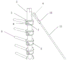
图1为本发明的立体结构示意图;Fig. 1 is the three-dimensional structure schematic diagram of the present invention;
图2为本发明中的螺纹立柱的结构示意图;Fig. 2 is the structural representation of threaded column among the present invention;
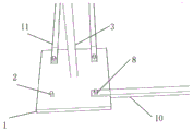
图3为本发明中的底座的结构示意图;Fig. 3 is the structural representation of the base in the present invention;
图4为本发明的侧视结构示意图;Fig. 4 is the side view structure schematic diagram of the present invention;
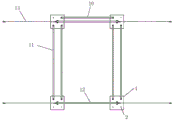
图5为本发明的固定链杆以及底座的结构示意图;Fig. 5 is a structural schematic diagram of the fixed chain rod and the base of the present invention;
图6为本发明的矩形钢筋笼制作的结构示意图;Fig. 6 is the structural representation that rectangular reinforcement cage of the present invention makes;
图7为本发明的矩形钢筋笼制作的侧视结构示意图;Fig. 7 is the side view structure schematic diagram that rectangular reinforcement cage of the present invention is made;
图8为本发明的矩形钢筋笼上吊施工的结构示意图;Fig. 8 is the structural schematic diagram of hanging construction of the rectangular reinforcement cage of the present invention;
图中:1、底座;2、螺纹杆;3、螺纹立柱;4、可拆卸钢钩;5、可调节定位环;6、圆形抱箍;7、螺栓;8、螺母;9、定位支撑杆;10、横向固定链杆;11、纵向固定链杆;12、顶部支撑杆;13、钢丝绳;14、钢丝绳卡扣;15、地锚;16、主筋;17、环绕矩形箍筋;18、竖向箍筋;19、横向箍筋。In the figure: 1. Base; 2. Threaded rod; 3. Threaded column; 4. Detachable steel hook; 5. Adjustable positioning ring; 6. Circular hoop; 7. Bolt; 8. Nut; 9. Positioning support Rod; 10, horizontal fixed chain rod; 11, vertical fixed chain rod; 12, top support rod; 13, wire rope; 14, wire rope buckle; 15, ground anchor; 16, main reinforcement; Vertical stirrups; 19. Horizontal stirrups.
具体实施方式Detailed ways
下面将结合本发明实施例中的附图,对本发明实施例中的技术方案进行清楚、完整地描述,显然,所描述的实施例仅仅是本发明一部分实施例,而不是全部的实施例。基于本发明中的实施例,本领域普通技术人员在没有做出创造性劳动前提下所获得的所有其他实施例,都属于本发明保护的范围。The following will clearly and completely describe the technical solutions in the embodiments of the present invention with reference to the accompanying drawings in the embodiments of the present invention. Obviously, the described embodiments are only some, not all, embodiments of the present invention. Based on the embodiments of the present invention, all other embodiments obtained by persons of ordinary skill in the art without making creative efforts belong to the protection scope of the present invention.
本发明提供如下技术方案:The present invention provides following technical scheme:
如图1-8所示,一种平面预制桥墩钢筋笼的模块化装置,包括设置在地面上的底座1以及插入地面设置的地锚15,底座1放置在地面上,地锚15放置在底座1的一侧,且地锚15的位置以及插入地面的深度根据装置本体的高度与重量以及钢丝绳13的长度来定;As shown in Figure 1-8, a modular device for a planar prefabricated pier reinforcement cage includes a
底座1设有若干个且呈两列设置,在每列底座1中相邻两个底座1之间以及位于两列底座1端部的底座1之间均通过固定链杆连接,通过固定链杆可将各个底座1连接起来,同时在本发明的实际使用时,可根据具体的加工需求,更换不同长度的固定链杆,以适用于不同规格的矩形钢筋笼的制作,同时能确保不同尺寸的矩形钢筋笼的精确度;There are
底座1上表面中心位置处焊接有螺纹立柱3,在两列底座1中相对的两根螺纹立柱3的顶端上可拆连接有顶部支撑杆12,具体为顶部支撑杆12放置在两根相对设置的螺纹立柱3的顶端,可轻易的将顶部支撑杆12取下,如此使得在矩形钢筋笼在制作完毕后,可轻易的将矩形钢筋笼取出,在螺纹立柱3的侧面留有一螺纹孔,螺纹孔内螺纹连接有可拆卸钢钩4,在本发明的实际安装时,需保证螺纹立柱3上的螺纹孔尽量靠近螺纹立柱3的顶部,避免可拆卸钢钩4的位置会影响可调节定位环5的调节,同时可拆卸钢钩4的位置会影响设置在螺纹立柱3顶部的两个可调定位环5之间的距离,如此使得在矩形钢筋笼制作时,矩形钢筋笼侧边上部的第一以及第二根主筋16的距离过大,从而影响钢筋笼的精度,地锚15的数量与底座1相对应,且其设置在底座1的外侧,可拆卸钢钩4与地锚15之间连接有钢丝绳13,通过钢丝绳13连接可拆卸钢钩4以及地锚15,能够进一步稳定本发明的整体结构,当在本发明提供的一种平面预制桥墩钢筋笼的模块化装置上进行矩形钢筋笼制作时,依靠钢丝绳13的拉力,能够防止装置本体以及矩形钢筋笼朝内侧倾覆;A threaded
螺纹立柱3上螺纹连接有若干竖向排列的可调节定位环5,可调节定位环5可在螺纹立柱3上自由移动,改变可调定位环5的高度以及相邻两个可调定位环5之间的间距,同时可调节定位环5的高度应该适当,高度过小会限制定位支撑杆9的直径,直径太小的定位支撑杆9容易在钢筋笼的重力影响下而弯曲过大,从而影响钢筋笼的精度,高度过大会影响相邻两个可调节定位环5的距离,从而影响钢筋笼侧边的主筋16的距离,可调节定位环5外圆周表面可拆连接有圆形抱箍6,圆形抱箍6的高度小于可调节定位环5的高度,圆形抱箍6由两个半圆形抱箍组成,且两个半圆形抱箍之间通过螺栓7与螺母8连接,其中一个半圆形抱箍上开设有螺纹开口,螺纹开口处螺纹连接有定位支撑杆9,在实际使用时,可通过转动定位支撑杆9使其脱离半圆形抱箍,同时通过将螺栓7以及螺母8拆除,可将圆形抱箍6从可调节定位环5上拆除,定位支撑杆9设置在两列底座1中相对的两根螺纹立柱3相互靠近的一侧上,在螺纹立柱3焊接到底座1上时,应其留有螺纹开口的方向垂直于底座1的一条边,同时需保证螺纹开口的方向朝内设置,即位于左列的螺纹立柱3,应使其螺纹开口朝右,位于右列的螺纹立柱3,应使其螺纹开口朝左,如此保证了两列对称设置的底座1上的螺纹立柱3上的定位支撑杆9均朝向相互靠近的一侧,如此以便于主筋16的放置,以便矩形钢筋笼的制作过程。The threaded
在每列底座1中相邻两个底座1之间通过纵向固定链杆11连接,位于两列底座1端部的底座1之间通过横向固定链杆10连接,本发明根据实际需要可更换安装不同长度的固定链杆,可以通过安装不同长度的横向固定链杆10和纵向固定链杆11,同时横向固定链杆10和纵向固定链杆11的数量根据底座1的数量来定,当底座1的数量为2n个,横向固定链杆10的数量为2个,纵向固定链杆11的数量为4n-4个,横向固定链杆10和纵向固定链杆11用于将底座1连接成一个整体,保证本发明的结构稳定性,同时也提高了本发明的承载能力。In each row of
底座1为方形钢板,在底座1靠近角点位置处焊接有四根螺纹杆2,横向固定链杆10与纵向固定链杆11通过螺母8与螺纹杆2连接,横向固定链杆10与纵向固定链杆11的两端均开有孔,孔的直径比螺纹杆2的直径略大,通过螺母8固定,能够增强装置的整体稳定性。The
横向固定链杆10与纵向固定链杆11的两端的厚度小于中间段的厚度,横向固定链杆10与纵向固定链杆11两端位置处设有开口朝下的直角凹槽,直角凹槽与底座1的棱边处相互配合,通过直角凹槽与底座1配合,能够防止相邻底座1之间的相对移动,这里将固定链杆的中间段长度视为其有效长度,固定链杆分为横向固定链杆10和纵向固定链杆11,根据预制矩形钢筋笼的宽度确定横向固定链杆10的长度,根据预制矩形钢筋笼的长度确定纵向固定链杆11的长度,两侧主筋16外侧的间距需略大于固定链杆的有效长度,保证两侧主筋16能够放在定位支撑杆9上。The thickness of the two ends of the horizontally fixed
螺纹立柱3为钢质实心柱,螺纹立柱3顶部留有开口槽一,顶部支撑杆12的两端设置在开口槽一内,且顶部支撑杆12的两端设有与之适配的开口槽二,通过螺纹立柱3上的开口槽一以及顶部支撑杆12上的开口槽二相互配合,如此限定顶部支撑杆12水平面上的位移,同时也便于顶部支撑杆12的取下。The threaded
钢丝绳13的两端均设置有绳套,绳套开口处连接有钢丝绳卡扣14,且地锚15伸出地面的一端固定有钩状体,钢丝绳13远离可拆卸钢钩4的一端连接在钩状体上,通过钢丝绳卡扣14能够固定住钢丝绳13的端部,通过钩状体以及可拆卸钢钩4的设置,便于钢丝绳13的固定。Both ends of the
在钢丝绳13处于拉紧状态时,钢丝绳13与地面之间的夹角为45度,同时应使得同一列的螺纹立柱3和地锚15所连接的钢丝绳13处于同一平面上,钢丝绳13给装置本体两侧的拉力,可防止钢筋笼过重而导致装置向内倾覆。When the
可调节定位环5的上下两端均设有沿其端面径向向外延伸出的外缘,圆形抱箍6设置在外缘之间,可调节定位环5为中间细两端粗的环状结构,通过外缘能够对圆形抱箍6进行限位。The upper and lower ends of the
定位支撑杆9具体为半螺纹杆,设置在定位支撑杆9一端的螺纹段与圆形抱箍6螺纹连接,定位支撑杆9伸出圆形抱箍6的部分为平直的杆状结构,以便用于放置制作矩形钢筋笼用的主筋16。The
在本发明在工厂预制环节中,各部件的参考尺寸如下:In the factory prefabrication link of the present invention, the reference dimensions of each component are as follows:
底座1由50×50×3cm的方形钢板制成,方形钢板的四个角处分别焊接一直径为2cm的螺纹杆2,螺纹杆2距底座相邻两边的距离为10cm;螺纹立柱3顶部的开口槽一宽度与高度均为3cm,螺纹孔的直径为1cm,可调节定位环5中间段的内径为5cm,外径为6cm,高0.5cm;两端的外缘内径为5cm,外径为8cm,高0.5cm;圆形抱箍6的高度为2.8cm,螺纹开口直径为2cm;定位支撑杆9为直径为2cm,长22cm;横向固定链杆10的中间段高度与宽度为3cm,长度根据预制钢筋笼的尺寸确定,两端的高度为1.5cm,宽度为3cm;顶部支撑杆12的两端也留有开口槽二,槽深1cm;当顶部支撑杆12设置好时,其上表面和螺纹立柱3顶面齐平,其宽度和高度为4cm,有效长度与横向固定链杆10的中间段长度相同;纵向固定链杆11与横向固定链杆10中间段长度不同,其他尺寸均相同,为了工厂模块化制作和施工便利,横向固定链杆10的中间段长度可10cm为一个单位来制造,纵向固定链杆11的中间段长度可设置为300cm,本发明中的模块化装置由各种模块化配件拼装而成,配件由工厂批量定制生产,保证了配件的低成本和高精确度,模块化配件轻便且体积小,方便运输至施工现场,且便于现场组装及拆卸,配件可重复使用,符合绿色环保理念。The base 1 is made of a square steel plate of 50×50×3cm, and a threaded rod 2 with a diameter of 2cm is welded to the four corners of the square steel plate, and the distance between the threaded rod 2 and the adjacent two sides of the base is 10cm; The width and height of opening groove one are 3cm, the diameter of threaded hole is 1cm, the inner diameter of adjustable positioning ring 5 middle section is 5cm, the outer diameter is 6cm, and the height is 0.5cm; the outer edge inner diameter of both ends is 5cm, and the outer diameter is 8cm , high 0.5cm; the height of the circular hoop 6 is 2.8cm, and the diameter of the threaded opening is 2cm; the positioning support rod 9 is 2cm in diameter and 22cm long; the middle section height and width of the horizontal fixed chain rod 10 are 3cm, and the length is according The size of prefabricated reinforcement cage is determined, and the height of two ends is 1.5cm, and width is 3cm; The two ends of top support rod 12 also leave opening groove 2, groove deep 1cm; When top support rod 12 is arranged, its upper surface and screw thread The top surface of the column 3 is flush, its width and height are 4cm, and the effective length is the same as the length of the middle section of the horizontally fixed chain bar 10; Factory modular production and convenient construction, the length of the middle section of the horizontal fixed chain bar 10 can be made as a unit of 10cm, the length of the middle section of the vertical fixed chain bar 11 can be set to 300cm, the modular device in the present invention consists of various modules Assembled with chemical parts, the parts are mass-customized and produced by the factory, which ensures the low cost and high accuracy of the parts. The modular parts are light and small in size, easy to transport to the construction site, and easy to assemble and disassemble on site. The parts can be reused. In line with the concept of green environmental protection.
一种矩形钢筋笼制作方法,利用以上的一种平面预制桥墩钢筋笼的模块化装置进行制作,制作方法包括以下步骤:A method for manufacturing a rectangular reinforcement cage, utilizing the above modularized device for a prefabricated bridge pier reinforcement cage to manufacture, the manufacturing method comprises the following steps:
本实施例以预制长9m,宽1.8m,高1.5m的矩形钢筋笼为实施例来对本发明进行进一步的解释和说明The present embodiment takes the prefabricated long 9m, wide 1.8m, the rectangular reinforcement cage of high 1.5m as embodiment to further explain and illustrate the present invention
场地选择:根据实际的加工需要,选择合适的场地,若施工场地地基较为软弱,则需要提前进行场地硬化平整处理,防止地表沉陷,影响装置的精度,如果施工场地地基满足施工要求,则可省略本步骤;Site selection: choose a suitable site according to the actual processing needs. If the foundation of the construction site is relatively weak, it is necessary to carry out site hardening and leveling treatment in advance to prevent surface subsidence and affect the accuracy of the device. If the foundation of the construction site meets the construction requirements, it can be omitted. this step;
装置拼装:根据预制的矩形钢筋笼的大小,计算出模块化装置的长度和宽度,选择有效长度为1.6m的横向固定链杆10、3m的纵向固定链杆11以及1.6m的顶部支撑杆12,根据现场已经测设好的测量控制网,利用全站仪对底座1位置进行放样定位,将底座1按照测设的位置摆放,设置成两列三行的矩阵形式,并使每一行或列的底座1中心在同一条直线上,其中每行的相邻底座1之间的距离为2.6m,每列的相邻底座1为3m,底座1的数量为6个,顶部支撑杆12的数量为3根,用两根横向固定链杆10连接第一行和第三行的相邻底座1,第二行的相邻底座1不需要用横向固定链杆10连接;纵向相邻底座1需要两根纵向固定链杆11连接,共需要8根纵向固定链杆11。钢筋笼沿高度方向的主筋16为14根,最顶部的主筋16放在顶部支撑杆12上,其余均放在定位支撑杆9上,则每个螺纹立柱3上需设13个可调节定位环5,共需要78个可调节定位环5,以顶部支撑杆12上表面为基准面,则第一个可调节定位环5设置在距顶部支撑杆12上表面12.9cm处,第2-12个可调节定位环5之间的距离均为10cm,第12个和第13个之间的距离为12.9cm。在每个可调节定位环5上都设置圆形抱箍6,将预留有螺纹开口的半圆形抱箍朝内,并安装好定位支撑杆9,定位支撑杆9的数量与可调节定位环5的数量相等,共需要78根。随后安装可拆卸钢钩4和顶部支撑杆12。最后将钢丝绳13一端连接可拆卸钢钩4,另一端连接地锚15,将钢丝绳13拉紧后,打入地锚15;Device assembly: Calculate the length and width of the modular device according to the size of the prefabricated rectangular steel cage, and select the horizontal fixed chain rod 10 with an effective length of 1.6m, the vertical fixed chain rod 11 with 3m and the top support rod 12 with an effective length of 1.6m , according to the survey control network that has been measured and set up on site, use the total station to stake out and position the position of the base 1, place the base 1 according to the measured position, set it into a matrix form of two columns and three rows, and make each row or The centers of bases 1 of the columns are on the same straight line, the distance between adjacent bases 1 of each row is 2.6m, the distance between adjacent bases 1 of each column is 3m, the number of bases 1 is 6, and the distance between the top support rods 12 The number is 3, and the adjacent bases 1 of the first and third rows are connected by two horizontal fixed chain rods 10, and the adjacent bases 1 of the second row do not need to be connected by horizontal fixed chain rods 10; the vertically adjacent bases 1 Two vertical fixed chain bars 11 are required to be connected, and a total of eight vertical fixed chain bars 11 are needed. There are 14
架设钢筋笼:将矩形钢筋笼顶部的主筋16按实际间距摆放在顶部支撑杆12上,设置环绕矩形箍筋17和竖向箍筋18,将环绕矩形箍筋17和竖向箍筋18沿纵向按固定间距摆放好,并与顶部的主筋16焊接,将两侧的主筋16的任意一侧摆放在与之对应一侧的定位支撑杆9上,并使这一侧所有主筋16沿高度方向对齐顶部最外侧的主筋16,再设置横向箍筋19,并将横向箍筋19与侧边的主筋16焊接连接,接着将另一侧的主筋16摆放在与之对应一侧的定位支撑杆9上,将底部的主筋16摆放在环绕矩形箍筋17上,最后,将环绕矩形箍筋17、竖向箍筋18以及横向箍筋19与对应的主筋16焊接好;Erection of the reinforcement cage: place the
起吊钢筋笼:在架设完矩形钢筋笼后,先将矩形钢筋笼整体向一侧上方吊起,使矩形钢筋笼不压在模块化装置上,且让其中一侧的所有定位支撑杆9脱离钢筋笼内部,并将与之对应一侧的所有可调节定位环5上的定位支撑杆9取下,接着,将矩形钢筋笼整体向另一侧移动,使与之对应一侧的所有定位支撑杆9脱离矩形钢筋笼内部,最后将矩形钢筋笼整体向上吊起,矩形钢筋笼将带着顶部支撑杆12一起与装置分开,而后取出顶部支撑杆12,矩形钢筋笼起吊结束;Lifting the reinforcement cage: After erecting the rectangular reinforcement cage, lift the rectangular reinforcement cage upwards to one side first, so that the rectangular reinforcement cage does not press on the modular device, and let all the
场地恢复:将预制矩形钢筋笼相关装置拆除,矩形钢筋笼运输至特定位置。Site restoration: The prefabricated rectangular reinforcement cages were removed and the rectangular reinforcement cages were transported to a specific location.
该矩形钢筋笼制作方法将由工人现场搭建脚手架高处作业改变为平面作业,大大的降低了工人的作业强度,且平面作业方便工人施工,节约时间,提高工效,提高钢筋笼精度,同时在矩形钢筋笼制作完毕后,先将矩形钢筋笼朝一侧上方吊起,而后取下一侧的定位支撑杆,再将矩形钢筋笼朝另一侧移动,而后取下另一侧的定位支撑杆,最后将矩形钢筋笼整体向上吊起,由于顶部支撑杆可拆在螺纹立柱上,使得矩形钢筋笼吊起后,可带动顶部支撑杆吊起并脱离螺纹立柱,上述矩形钢筋笼的吊起过程,过程简单方便,且不用整体拆解模块化装置,较大程度上提高了矩形钢筋笼的加工效率,同时也便于进行下一次的矩形钢筋笼的制作,省去了模块化装置拆解以及重新安装的步骤。The manufacturing method of the rectangular steel cage changes the work at the height of the scaffold built by the workers on site to the plane work, which greatly reduces the work intensity of the workers, and the plane work is convenient for the workers to construct, saves time, improves work efficiency, and improves the accuracy of the steel cage. After the cage is finished, first lift the rectangular reinforcement cage upward on one side, then remove the positioning support rod on one side, then move the rectangular reinforcement cage to the other side, then remove the positioning support rod on the other side, and finally place the The rectangular steel cage is hoisted upwards as a whole. Since the top support rod can be disassembled on the threaded column, after the rectangular steel cage is hoisted, the top support rod can be lifted and separated from the threaded column. The lifting process of the above rectangular steel cage is simple. It is convenient and does not need to disassemble the modular device as a whole, which greatly improves the processing efficiency of the rectangular steel cage, and is also convenient for the next production of the rectangular steel cage, eliminating the steps of dismantling and reinstalling the modular device .
以上公开的本发明优选实施例只是用于帮助阐述本发明。优选实施例并没有详尽叙述所有的细节,也不限制该发明仅为的具体实施方式。显然,根据本说明书的内容,可作很多的修改和变化。本说明书选取并具体描述这些实施例,是为了更好地解释本发明的原理和实际应用,从而使所属技术领域技术人员能很好地理解和利用本发明。本发明仅受权利要求书及其全部范围和等效物的限制。The preferred embodiments of the invention disclosed above are only to help illustrate the invention. The preferred embodiments do not exhaust all details nor limit the invention to only specific embodiments. Obviously, many modifications and variations can be made based on the contents of this specification. This description selects and specifically describes these embodiments in order to better explain the principle and practical application of the present invention, so that those skilled in the art can well understand and utilize the present invention. The invention is to be limited only by the claims, along with their full scope and equivalents.
Claims (9)
Priority Applications (1)
| Application Number | Priority Date | Filing Date | Title |
|---|---|---|---|
| CN202111426315.9A CN114054651B (en) | 2021-11-27 | 2021-11-27 | Modularized device of plane precast pier reinforcement cage and rectangular reinforcement cage manufacturing method |
Applications Claiming Priority (1)
| Application Number | Priority Date | Filing Date | Title |
|---|---|---|---|
| CN202111426315.9A CN114054651B (en) | 2021-11-27 | 2021-11-27 | Modularized device of plane precast pier reinforcement cage and rectangular reinforcement cage manufacturing method |
Publications (2)
| Publication Number | Publication Date |
|---|---|
| CN114054651A CN114054651A (en) | 2022-02-18 |
| CN114054651B true CN114054651B (en) | 2023-05-30 |
Family
ID=80276746
Family Applications (1)
| Application Number | Title | Priority Date | Filing Date |
|---|---|---|---|
| CN202111426315.9A Active CN114054651B (en) | 2021-11-27 | 2021-11-27 | Modularized device of plane precast pier reinforcement cage and rectangular reinforcement cage manufacturing method |
Country Status (1)
| Country | Link |
|---|---|
| CN (1) | CN114054651B (en) |
Families Citing this family (6)
| Publication number | Priority date | Publication date | Assignee | Title |
|---|---|---|---|---|
| CN115030137B (en) * | 2022-07-13 | 2023-10-31 | 上海建工四建集团有限公司 | Underground diaphragm wall reinforcement cage positioning and adjusting device and construction method thereof |
| CN114888210A (en) * | 2022-07-14 | 2022-08-12 | 中建八局第二建设有限公司 | Steel reinforcement cage main reinforcement positioning tool and use method thereof |
| CN115283586B (en) * | 2022-07-29 | 2025-07-22 | 中交第二航务工程局有限公司 | Bridge pier body block type steel bar part matching manufacturing method |
| CN115613811A (en) * | 2022-10-25 | 2023-01-17 | 中国核工业二四建设有限公司 | Modular construction tooling and method for straight wall reinforcement cage |
| CN116511795B (en) * | 2023-05-04 | 2025-05-13 | 中国化学工程第三建设有限公司 | Machining equipment, machining method and sleeving method for double-anchor-plate opposite-pulling embedded part |
| CN116464294B (en) * | 2023-05-23 | 2026-02-27 | 中建七局安装工程有限公司 | Horizontal support system for tying column rebar cages |
Family Cites Families (10)
| Publication number | Priority date | Publication date | Assignee | Title |
|---|---|---|---|---|
| JP2648904B2 (en) * | 1994-10-11 | 1997-09-03 | 株式会社高橋製作所 | Method of assembling beam rebar and work support for it |
| JP3058809B2 (en) * | 1995-02-22 | 2000-07-04 | ライト工業株式会社 | Reinforcing bar formwork |
| JPH10216878A (en) * | 1997-01-31 | 1998-08-18 | Taisei Corp | Assembling method, assembling apparatus, and assembling jig for reinforced cage |
| CN203834361U (en) * | 2014-04-25 | 2014-09-17 | 中交二航局第四工程有限公司 | Integral prefabricated molding bed of cross-sea bridge wide pier body steel reinforcement cage |
| CN104264590B (en) * | 2014-09-30 | 2016-01-20 | 中交二航局第四工程有限公司 | A kind of prefabricated moulding bed of pier stud reinforcing bar simultaneously accurately can locating main muscle and stirrup |
| CN105437367B (en) * | 2015-12-25 | 2018-01-09 | 上海建工四建集团有限公司 | A kind of preparation method of reinforcing bar moulding bed and steel reinforcement cage |
| CN108396650B (en) * | 2018-02-02 | 2024-03-19 | 中铁四局集团有限公司 | A continuous rigid frame PC track beam steel cage binding device |
| CN212042460U (en) * | 2020-01-06 | 2020-12-01 | 湖北省路桥集团有限公司 | Pile foundation reinforcement cage manufacturing and positioning device |
| CN113458299A (en) * | 2020-03-31 | 2021-10-01 | 比亚迪股份有限公司 | Positioning device for binding reinforcement cage |
| CN112275963B (en) * | 2020-09-30 | 2022-05-03 | 湖南梅溪湖建设有限公司 | Rapid positioning, installing and constructing method for prefabricated frame column reinforcement cage |
-
2021
- 2021-11-27 CN CN202111426315.9A patent/CN114054651B/en active Active
Also Published As
| Publication number | Publication date |
|---|---|
| CN114054651A (en) | 2022-02-18 |
Similar Documents
| Publication | Publication Date | Title |
|---|---|---|
| CN114054651A (en) | Modularization device of plane prefabricated pier reinforcement cage and rectangular reinforcement cage manufacturing method | |
| CN107090932B (en) | Construction method of large-span thin-wall plane arch truss based on stiff ring beam | |
| CN110512719B (en) | Construction method of large-span interval corridor high-altitude formwork steel platform for high-rise residence | |
| KR102019193B1 (en) | Construction method of reinforced soil retaining wall | |
| CN116290838A (en) | A steel bar binding bracket assembly and a steel bar skeleton construction method | |
| CN212053673U (en) | Tower construction operation platform of dome | |
| CN212743356U (en) | Reverse construction method hangs mould system | |
| CN220928427U (en) | Can assemble dismantlement formula lattice column structure | |
| CN112554534A (en) | Construction method of large silo dome concrete | |
| CN116220379B (en) | Annular beam structure node reinforcement frame body device and annular beam construction method | |
| JP7339477B2 (en) | Concrete column formwork construction device and concrete column formwork construction method using the same | |
| CN218323497U (en) | A prefabricated pier column reinforcement cage | |
| JP2002038475A (en) | Deep foundation pile construction method | |
| JP4623570B2 (en) | Construction method of jack base and formwork support | |
| CN110761295A (en) | Prefabricated assembled concrete pipe props structure | |
| CN212478488U (en) | Construction work platform is built by laying bricks or stones to chimney inside lining | |
| CN104372948A (en) | Elevator shaft formwork lifting frame | |
| JP2001295404A (en) | Hollow tube driving method with rebar | |
| CN211713706U (en) | A large cantilever prefabricated cover beam installation lattice support device | |
| CN223135660U (en) | A flat floor forming structure that is easy to disassemble and assemble | |
| CN115627879B (en) | A precast pier column reinforcement cage and its overall hoisting construction method | |
| CN112195802A (en) | Variable-section U-shaped hollow thin-wall pier steel bar partition prefabricated jig frame and partition installation method | |
| KR20220112000A (en) | Descent apparatus downward construction system method using thereof | |
| CN115538594B (en) | A beam-column positioning structure for an assembled concrete structure | |
| CN222576243U (en) | A building construction frame that is easy to assemble |
Legal Events
| Date | Code | Title | Description |
|---|---|---|---|
| PB01 | Publication | ||
| PB01 | Publication | ||
| SE01 | Entry into force of request for substantive examination | ||
| SE01 | Entry into force of request for substantive examination | ||
| GR01 | Patent grant | ||
| GR01 | Patent grant |