CN114050692A - Winding device is used in production of generator stator coil - Google Patents
Winding device is used in production of generator stator coil Download PDFInfo
- Publication number
- CN114050692A CN114050692A CN202210035887.2A CN202210035887A CN114050692A CN 114050692 A CN114050692 A CN 114050692A CN 202210035887 A CN202210035887 A CN 202210035887A CN 114050692 A CN114050692 A CN 114050692A
- Authority
- CN
- China
- Prior art keywords
- fixedly connected
- rod
- wire guide
- base
- winding device
- Prior art date
- Legal status (The legal status is an assumption and is not a legal conclusion. Google has not performed a legal analysis and makes no representation as to the accuracy of the status listed.)
- Pending
Links
- 238000004804 winding Methods 0.000 title claims abstract description 21
- 238000004519 manufacturing process Methods 0.000 title claims description 19
- 230000007246 mechanism Effects 0.000 claims abstract description 9
- 239000011248 coating agent Substances 0.000 claims description 5
- 238000000576 coating method Methods 0.000 claims description 5
- 230000008878 coupling Effects 0.000 claims description 5
- 238000010168 coupling process Methods 0.000 claims description 5
- 238000005859 coupling reaction Methods 0.000 claims description 5
- 230000000149 penetrating effect Effects 0.000 claims description 2
- RYGMFSIKBFXOCR-UHFFFAOYSA-N Copper Chemical compound [Cu] RYGMFSIKBFXOCR-UHFFFAOYSA-N 0.000 description 13
- 229910052802 copper Inorganic materials 0.000 description 7
- 239000010949 copper Substances 0.000 description 7
- 230000008859 change Effects 0.000 description 4
- 230000000694 effects Effects 0.000 description 4
- 238000009434 installation Methods 0.000 description 4
- 230000001681 protective effect Effects 0.000 description 4
- 238000000465 moulding Methods 0.000 description 3
- 230000001737 promoting effect Effects 0.000 description 3
- 239000000428 dust Substances 0.000 description 2
- 238000001125 extrusion Methods 0.000 description 2
- 239000000463 material Substances 0.000 description 2
- 238000000034 method Methods 0.000 description 2
- 230000008569 process Effects 0.000 description 2
- 230000000052 comparative effect Effects 0.000 description 1
- 230000007547 defect Effects 0.000 description 1
- 238000010586 diagram Methods 0.000 description 1
- 239000002657 fibrous material Substances 0.000 description 1
- 238000012986 modification Methods 0.000 description 1
- 230000004048 modification Effects 0.000 description 1
- 238000010248 power generation Methods 0.000 description 1
Images



Classifications
-
- H—ELECTRICITY
- H02—GENERATION; CONVERSION OR DISTRIBUTION OF ELECTRIC POWER
- H02K—DYNAMO-ELECTRIC MACHINES
- H02K15/00—Processes or apparatus specially adapted for manufacturing, assembling, maintaining or repairing of dynamo-electric machines
- H02K15/08—Forming windings by laying conductors into or around core parts
Landscapes
- Engineering & Computer Science (AREA)
- Manufacturing & Machinery (AREA)
- Power Engineering (AREA)
- Manufacture Of Motors, Generators (AREA)
Abstract
The invention relates to the technical field of processing and producing motor parts of motorcycles, in particular to a winding device for producing a stator coil of a generator, which comprises a base, a supporting plate, a wire roller and an adjusting mechanism, wherein the base is provided with a plurality of winding holes; the wire roller is rotatably connected to the top of the base; the two supporting plates are fixedly connected to the bottom of the base; the adjusting mechanism comprises a first motor, a worm gear, a rack and a wire guide plate; the first motor is fixedly connected to the top of the base; the output shaft of the first motor is fixedly connected with a first rod, and the outer wall of the first rod is sleeved and fixedly connected with a worm; the side wall of the supporting plate is rotatably connected with a second rod, the worm wheel is sleeved and fixedly connected with the second rod, and the worm wheel are in a meshed state; one end of the second rod is also sleeved and fixedly connected with a gear; the height of the wire guide plate is changed, so that the coil wound on the stator is uniformly paved on the wire guide plate, and the coil is uniformly distributed on the stator.
Description
Technical Field
The invention relates to the technical field of processing and producing of parts of a motorcycle generator, in particular to a winding device for producing a stator coil of a generator.
Background
The generator is a common power generation device and is widely applied to production life, and copper wires need to be wound on the stator during production work of the generator.
In the use process of the existing winding device, the phenomenon of uneven coil distribution on the stator caused by unchanged input height of a copper wire can occur, so that the produced stator can not meet the production requirement; therefore, the winding device for producing the stator coil of the generator is provided for solving the problems.
Disclosure of Invention
The invention provides a winding device for producing a stator coil of a generator, aiming at making up the defects of the prior art and solving the problem that the coils wound on a stator are not uniformly distributed due to the unchanged input height of a copper wire in the use process of the conventional winding device, so that the produced stator can not meet the production requirement.
The technical scheme adopted by the invention for solving the technical problems is as follows: the invention relates to a winding device for producing a stator coil of a generator, which comprises a base, a supporting plate, a wire roller and an adjusting mechanism, wherein the supporting plate is arranged on the base; the wire roller is rotatably connected to the top of the base; the two supporting plates are fixedly connected to the bottom of the base; the adjusting mechanism comprises a first motor, a worm gear, a rack and a wire guide plate; the first motor is fixedly connected to the top of the base; the output shaft of the first motor is fixedly connected with a first rod, and the outer wall of the first rod is sleeved and fixedly connected with a worm; the side wall of the supporting plate is rotatably connected with a second rod, the worm wheel is sleeved and fixedly connected with the second rod, and the worm wheel are in a meshed state; one end of the second rod is also sleeved and fixedly connected with a gear; the rack penetrates through and is rotatably connected to the top of the base, and the gear and the rack are in a meshed state; the wire guide plate is fixedly connected to the top of the rack; the height of the wire guide plate is changed, so that the coil wound on the stator is uniformly paved on the wire guide plate, and the coil is uniformly distributed on the stator.
Preferably, the side wall of the wire guide plate is provided with a wire guide groove, and the inner wall of the wire guide groove is rotatably connected with two wire guide wheels; the height of copper wire place can be adjusted, and the coil is evenly distributed on the stator.
Preferably, the bottom of the base is fixedly connected with a second motor, and an output shaft of the second motor is fixedly connected with a turntable; the turntable is positioned at the top of the base and is in sliding fit with the top of the base; the top of the turntable is provided with an installation groove, and a stator is installed in the installation groove; the second motor drives the turntable to rotate, so that the stator rotates along with the turntable, and the copper wire is wound on the stator.
Preferably, one side of the turntable is connected with a third rod in a penetrating and sliding manner; two cavities are symmetrically arranged in the turntable, the outer wall of the third rod is sleeved on the part of the cavity and fixedly connected with a first plate, and the top of the cavity is fixedly connected with an air bag; two piston cylinders are symmetrically and fixedly connected to the two sides of the mounting groove in the turntable; the air bag is communicated with a rodless cavity of the piston cylinder; the two clamping plates move simultaneously, so that the stator can be fixed in the mounting groove.
Preferably, a piston rod of the piston cylinder penetrates through and is connected to the inner wall of the mounting groove in a sliding mode; one end of the piston rod, which is positioned in the mounting groove, is fixedly connected with a clamping plate; a spring is fixedly connected between the clamping plate and the inner wall of the mounting groove; by arranging the spring, when the first plate does not press the air bag, the elastic force of the spring can enable the splint to return to the initial position.
Preferably, the outer surface of the air bag is wrapped with a maximum deformation limiting layer, and the maximum volume of the air bag is limited.
Preferably, one end of the third rod, which is positioned outside the turntable, is fixedly connected with a push plate, one side of the push plate, which is close to the turntable, is fixedly connected with a first magnet, and the side wall of the turntable is fixedly connected with a second magnet; the stator fixing effect can be improved.
Preferably, the first magnet and the second magnet are both two groups and are symmetrically arranged by a rotating shaft of the third rod respectively.
Preferably, the wire guide wheel is rotationally inserted with the wire guide groove in a buckling manner, and a plurality of annular wire grooves surrounding the cylindrical surface of the wire guide wheel are arranged on the cylindrical surface of the wire guide wheel.
Preferably, the surface of the clamping plate, which is in contact with the stator, is provided with a modeling surface matched with the surface contour of the stator, and the modeling surface is coated with a friction-increasing coating.
The invention has the advantages that:
1. the adjusting mechanism is arranged, the first motor drives the first rod to rotate, the worm and the worm wheel are enabled to generate meshing motion, the gear is enabled to rotate, the gear and the rack are enabled to generate meshing motion, the rack is enabled to generate up-and-down motion, the height of the wire guide plate is enabled to change, the coils wound on the stator are enabled to be evenly paved on the wire guide plate, and the coils are enabled to be evenly distributed on the stator.
2. The air bag is extruded by the plate I on the outer wall of the rod III, so that gas in the air bag enters a rodless cavity of the piston cylinder, the piston plate is pushed to move in the piston cylinder, the clamping plate is fixedly connected to the other end of the piston rod and abuts against the outer wall of the stator, the two clamping plates move simultaneously, the stator can be fixed in the mounting groove, and the stator is convenient to mount.
Drawings
In order to more clearly illustrate the embodiments of the present invention or the technical solutions in the prior art, the drawings used in the description of the embodiments or the prior art will be briefly described below, and it is obvious that the drawings in the following description are only some embodiments of the present invention, and for those skilled in the art, other drawings can be obtained according to these drawings without inventive exercise.
FIG. 1 is a schematic partial cross-sectional view illustrating a structure according to a first embodiment;
FIG. 2 is a schematic view of a wire guide plate according to an embodiment;
FIG. 3 is an enlarged view of a portion of the area A in FIG. 1;
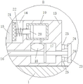
FIG. 4 is an enlarged view of a portion of the area B in FIG. 1;
fig. 5 is a schematic partial cross-sectional structure diagram of the second embodiment.
In the figure: 1. a base; 2. a support plate; 3. a wire roller; 4. a first motor; 5. a worm gear; 6. a rack; 7. a wire guide plate; 8. a worm; 9. a second rod; 10. a gear; 11. a wire guide wheel; 12. a second motor; 13. a turntable; 14. mounting grooves; 15. a stator; 16. a third rod; 17. a first board; 18. an air bag; 19. a piston cylinder; 20. a piston rod; 21. a splint; 22. a spring; 23. pushing the plate; 24. a magnet I; 25. a second magnet; 26. a protective housing; 27. a first rod.
Detailed Description
The technical solutions in the embodiments of the present invention will be clearly and completely described below with reference to the drawings in the embodiments of the present invention, and it is obvious that the described embodiments are only a part of the embodiments of the present invention, and not all of the embodiments. All other embodiments, which can be derived by a person skilled in the art from the embodiments given herein without making any creative effort, shall fall within the protection scope of the present invention.
Example one
Referring to fig. 1-4, a winding device for generator stator coil production includes a base 1, a supporting plate 2, a wire roller 3 and an adjusting mechanism; the wire roller 3 is rotatably connected to the top of the base 1; the two supporting plates 2 are fixedly connected to the bottom of the base 1; the adjusting mechanism comprises a first motor 4, a worm wheel 5, a rack 6 and a wire guide plate 7; the first motor 4 is fixedly connected to the top of the base 1; a first rod 27 is fixedly connected to an output shaft of the first motor 4, and a worm 8 is sleeved and fixedly connected to the outer wall of the first rod 27; the side wall of the supporting plate 2 is rotatably connected with a second rod 9, the worm wheel 5 is sleeved and fixedly connected with the second rod 9, and the worm 8 is meshed with the worm wheel 5; one end of the second rod 9 is also sleeved and fixedly connected with a gear 10; the rack 6 penetrates through and is rotatably connected to the top of the base 1, and the gear 10 is meshed with the rack 6; the wire guide plate 7 is fixedly connected to the top of the rack 6; during operation, the copper line on the line roller 3 passes between two wire wheel 11, and around on stator 15, through starting a motor 4, make a motor 4 drive a pole 27 and worm 8 and rotate, make worm 8 and worm wheel 5 produce meshing motion, make worm wheel 5 drive No. two poles 9 and rotate, and then make gear 10 produce the rotation, then produce meshing motion between gear 10 and the rack 6, will make rack 6 produce the up-and-down motion, and then make the high change that produces at wire guide 7 place, make the even shop of coil around on stator 15 above that, make the coil evenly distribute on stator 15.
The side wall of the wire guide plate 7 is provided with a wire guide groove, and the inner wall of the wire guide groove is rotatably connected with two wire guide wheels 11; during operation, copper line passes between two wire wheels 11 from the metallic channel on the line roller 3, realizes the guide to the copper line, and the up-and-down motion of wire guide 7 simultaneously can adjust the height at copper line place, makes the coil distribute evenly on stator 15.
A second motor 12 is fixedly connected to the bottom of the base 1, and a rotary disc 13 is fixedly connected to an output shaft of the second motor 12; the rotary table 13 is positioned at the top of the base 1 and is in sliding fit with the top of the base 1; the top of the rotating disc 13 is provided with a mounting groove 14, and a stator 15 is mounted in the mounting groove 14; in operation, the stator 15 is installed in the installation groove 14, and the second motor 12 is started at the same time, so that the second motor 12 drives the rotating disc 13 to rotate, and then the stator 15 rotates along with the rotating disc 13, so that the copper wire is wound on the stator 15.
A third rod 16 penetrates through and is connected with one side of the rotary table 13 in a sliding manner; two cavities are symmetrically arranged in the rotary table 13, the outer wall of the third rod 16 is sleeved on the cavity and fixedly connected with a first plate 17, and the top of the cavity is fixedly connected with an air bag 18; two piston cylinders 19 are symmetrically and fixedly connected to the two sides of the mounting groove 14 in the rotary table 13; the air bag 18 is communicated with a rodless cavity of the piston cylinder 19; during operation, through promoting No. three pole 16 for No. three board 17 extrusion gasbag 18 of No. 16 outer walls of pole, make the inside gas of gasbag 18 get into the no pole chamber of piston cylinder 19, and then promote the piston plate and remove in piston cylinder 19, make the other end rigid coupling of piston rod 20 have splint 21 to support on the outer wall of stator 15, two splint 21 simultaneous movement can fix stator 15 in mounting groove 14.
A piston rod 20 of the piston cylinder 19 penetrates through and is connected to the inner wall of the mounting groove 14 in a sliding manner; one end of the piston rod 20, which is positioned in the mounting groove 14, is fixedly connected with a clamping plate 21; a spring 22 is fixedly connected between the clamping plate 21 and the inner wall of the mounting groove 14; in operation, by arranging the spring 22, when the first plate 17 does not squeeze the air bag 18, the elastic force of the spring 22 will make the clamp plate 21 return to the initial position, so that the gas in the rodless cavity of the piston cylinder 19 returns to the air bag 18, and the stator 15 is convenient to detach.
A push plate 23 is fixedly connected to one end, located outside the rotary disc 13, of the third rod 16, a first magnet 24 is fixedly connected to one side, close to the rotary disc 13, of the push plate 23, and a second magnet 25 is fixedly connected to the side wall of the rotary disc 13; the during operation is through promoting push pedal 23 for push pedal 23 drives No. three pole 16 and slides, and after two splint 21 fixed stator 15 in mounting groove 14, magnet 24 also adsorbed together with magnet two 25, realizes the fixed to push pedal 23, and the difficult production in position of splint 21 changes this moment, improves the fixed effect to stator 15.
The first magnet 24 and the second magnet 25 are both two groups and are respectively and symmetrically arranged by the rotating shaft of the third rod 16. The force can be uniformly applied when the third rod is driven to slide, so that the air bag is pressed more accurately.
The wire guide wheel 11 is rotationally inserted with the wire guide groove in a buckling mode, and a plurality of annular wire grooves surrounding the cylindrical surface of the wire guide wheel 11 are formed in the cylindrical surface of the wire guide wheel. Different direction recesses can adapt to the stator of different copper line diameters, and the buckle rotates to peg graft, adopts to set up the inserted bar on leading wheel 11, and the overcoat bearing is gone up to the inserted bar, sets up the spring snap ring again on the outer face of cylinder of bearing for with wire wheel inlay card be connected, can conveniently change the wire wheel.
The surface of splint 21 and stator contact is equipped with the molding face that matches with stator surface profile, and the coating has the coating of increasing friction on the molding face.
The molding surface can better hold the stator 15, and the friction increasing coating can increase the friction force, so that the holding effect is better.
The outer surface of the air bag 18 is wrapped with a maximum deformation limiting layer, and the maximum volume of the air bag 18 is limited.
The maximum deformation limiting layer can be made of fiber materials which are not elastic but can be bent and wrapped on the surface of the maximum deformation limiting layer to protect the air bag.
Example two
Referring to fig. 5, in a first comparative example, as another embodiment of the present invention, a protective casing 26 is fixed to the bottom of the base 1, and the second motor 12 is located inside the protective casing 26; during operation, through setting up protective housing 26 for No. two motors 12 are protected, and external dust will not contact with No. two motors 12 in a large number this moment, also can not appear the dust and get into No. two motors 12 inside and the motor radiating effect that leads to descends phenomenon.
The working principle is as follows: copper line passes between two wire wheels 11 in the wire guide from the wire casing on the line roller 3, and wind on stator 15, through starting a motor 4, make a motor 4 drive a pole 27 and worm 8 rotate, make worm 8 and worm wheel 5 produce meshing motion, make worm wheel 5 drive No. two poles 9 and rotate, and then make gear 10 produce the rotation, then produce meshing motion between gear 10 and the rack 6, will make rack 6 produce the up-and-down motion, and then make the high production at wire guide 7 place change, make the even shop of coil on stator 15 above that, make the coil evenly distribute on stator 15.
The stator 15 is installed in the installation groove 14, and the second motor 12 is started at the same time, so that the second motor 12 drives the rotary table 13 to rotate, and then the stator 15 rotates along with the rotary table 13, so that the copper wire is wound on the stator 15; through promoting No. three pole 16 for No. three board 17 extrusion gasbag 18 of No. 16 outer walls of pole, make the inside gas of gasbag 18 get into the no pole chamber of piston cylinder 19, and then promote the piston plate and remove in piston cylinder 19, make piston rod 20 other end rigid coupling have splint 21 to support on the outer wall of stator 15, two splint 21 simultaneous movement can fix stator 15 in mounting groove 14.
The front, the back, the left, the right, the upper and the lower are all based on figure 1 in the attached drawings of the specification, according to the standard of the observation angle of a person, the side of the device facing an observer is defined as the front, the left side of the observer is defined as the left, and the like.
In the description herein, references to the description of "one embodiment," "an example," "a specific example" or the like are intended to mean that a particular feature, structure, material, or characteristic described in connection with the embodiment or example is included in at least one embodiment or example of the invention. In this specification, the schematic representations of the terms used above do not necessarily refer to the same embodiment or example. Furthermore, the particular features, structures, materials, or characteristics described may be combined in any suitable manner in any one or more embodiments or examples.
The foregoing shows and describes the general principles, essential features, and advantages of the invention. It will be understood by those skilled in the art that the present invention is not limited to the embodiments described above, which are described in the specification and illustrated only to illustrate the principle of the present invention, but that various changes and modifications may be made therein without departing from the spirit and scope of the present invention, which fall within the scope of the invention as claimed.
Claims (10)
1. The utility model provides a wire winding device is used in production of generator stator coil which characterized in that: comprises a base (1), a supporting plate (2), a wire roller (3) and an adjusting mechanism; the wire roller (3) is rotatably connected to the top of the base (1); the two supporting plates (2) are fixedly connected to the bottom of the base (1); the adjusting mechanism comprises a first motor (4), a worm gear (5), a rack (6) and a wire guide plate (7); the first motor (4) is fixedly connected to the top of the base (1); a first rod (27) is fixedly connected to an output shaft of the first motor (4), and a worm (8) is sleeved and fixedly connected to the outer wall of the first rod (27); the side wall of the supporting plate (2) is rotatably connected with a second rod (9), the worm wheel (5) is sleeved and fixedly connected with the second rod (9), and the worm (8) and the worm wheel (5) are in a meshed state; one end of the second rod (9) is also sleeved and fixedly connected with a gear (10); the rack (6) penetrates through and is rotatably connected to the top of the base (1), and the gear (10) is meshed with the rack (6); the wire guide plate (7) is fixedly connected to the top of the rack (6).
2. The winding device for generator stator coil production according to claim 1, characterized in that: the side wall of the wire guide plate (7) is provided with a wire guide groove, and the inner wall of the wire guide groove is rotatably connected with two wire guide wheels (11).
3. The winding device for generator stator coil production according to claim 2, characterized in that: a second motor (12) is fixedly connected to the bottom of the base (1), and a rotary disc (13) is fixedly connected to an output shaft of the second motor (12); the rotary table (13) is positioned at the top of the base (1) and is in sliding fit with the top of the base (1); the top of carousel (13) has seted up mounting groove (14), install stator (15) in mounting groove (14).
4. The winding device for generator stator coil production according to claim 3, characterized in that: one side of the rotary table (13) is connected with a third rod (16) in a penetrating and sliding manner; two cavities are symmetrically arranged in the rotary table (13), the outer wall of the third rod (16) is sleeved at the part of the cavity and fixedly connected with a first plate (17), and the top of the cavity is fixedly connected with an air bag (18); two piston cylinders (19) are symmetrically and fixedly connected to the two sides of the mounting groove (14) in the rotary table (13); the air bag (18) is communicated with a rodless cavity of the piston cylinder (19).
5. The winding device for generator stator coil production according to claim 4, wherein: a piston rod (20) of the piston cylinder (19) penetrates through and is connected to the inner wall of the mounting groove (14) in a sliding mode; one end of the piston rod (20) positioned in the mounting groove (14) is fixedly connected with a clamping plate (21); and a spring (22) is fixedly connected between the clamping plate (21) and the inner wall of the mounting groove (14).
6. The winding device for generator stator coil production according to claim 4, wherein: the outer surface of the air bag (18) is wrapped with a maximum deformation limiting layer, and the maximum volume of the air bag (18) is limited.
7. The winding device for generator stator coil production according to claim 5, characterized in that: no. three pole (16) are located carousel (13) outer one end rigid coupling and have push pedal (23), push pedal (23) have magnet one (24) in the one side rigid coupling that is close to carousel (13), the lateral wall rigid coupling of carousel (13) has magnet two (25).
8. The winding device for generator stator coil production according to claim 7, characterized in that: the first magnet (24) and the second magnet (25) are two groups and are respectively and symmetrically arranged by a rotating shaft of the third rod (16).
9. The winding device for generator stator coil production according to claim 2, characterized in that: the wire guide wheel (11) is rotationally inserted with the wire guide groove buckle, and a plurality of annular wire grooves surrounding the cylindrical surface of the wire guide wheel (11) are arranged on the cylindrical surface.
10. The winding device for generator stator coil production according to claim 5, characterized in that: the surface of the clamping plate (21) in contact with the stator is provided with a modeling surface matched with the surface contour of the stator, and the modeling surface is coated with a friction-increasing coating.
Priority Applications (1)
| Application Number | Priority Date | Filing Date | Title |
|---|---|---|---|
| CN202210035887.2A CN114050692A (en) | 2022-01-13 | 2022-01-13 | Winding device is used in production of generator stator coil |
Applications Claiming Priority (1)
| Application Number | Priority Date | Filing Date | Title |
|---|---|---|---|
| CN202210035887.2A CN114050692A (en) | 2022-01-13 | 2022-01-13 | Winding device is used in production of generator stator coil |
Publications (1)
| Publication Number | Publication Date |
|---|---|
| CN114050692A true CN114050692A (en) | 2022-02-15 |
Family
ID=80196494
Family Applications (1)
| Application Number | Title | Priority Date | Filing Date |
|---|---|---|---|
| CN202210035887.2A Pending CN114050692A (en) | 2022-01-13 | 2022-01-13 | Winding device is used in production of generator stator coil |
Country Status (1)
| Country | Link |
|---|---|
| CN (1) | CN114050692A (en) |
Cited By (2)
| Publication number | Priority date | Publication date | Assignee | Title |
|---|---|---|---|---|
| CN120546388A (en) * | 2025-05-26 | 2025-08-26 | 台州泰立电器有限公司 | A stator and rotor coil winding machine for an excitation motor |
| CN120613896A (en) * | 2025-08-11 | 2025-09-09 | 江苏大中电机股份有限公司 | A winding device for motor production with tension self-adjustment function |
Citations (8)
| Publication number | Priority date | Publication date | Assignee | Title |
|---|---|---|---|---|
| CN209860762U (en) * | 2019-05-26 | 2019-12-27 | 天津瑞派机电科技有限公司 | Winding device for motor maintenance |
| CN211321168U (en) * | 2019-11-28 | 2020-08-21 | 潍坊科技学院 | A kind of motor iron core winding equipment |
| CN211491411U (en) * | 2019-12-31 | 2020-09-15 | 武汉经纬朗博检测技术有限公司 | Jack calibrating installation |
| CN112003434A (en) * | 2020-07-31 | 2020-11-27 | 黄连芝 | Coil winding device of rotor winding for motor production |
| CN112260498A (en) * | 2020-10-14 | 2021-01-22 | 杨武秀 | Coil winding device for motor production |
| CN214337554U (en) * | 2021-02-08 | 2021-10-01 | 合肥雷凯科技有限公司 | Intelligent arc extinction and overvoltage protection device |
| CN214672215U (en) * | 2021-06-21 | 2021-11-09 | 博罗县嘉治电子有限公司 | Coil winding device for transformer processing |
| CN214959201U (en) * | 2021-06-17 | 2021-11-30 | 年丰(福建)电机有限公司 | Coil auxiliary winding device for generator production |
-
2022
- 2022-01-13 CN CN202210035887.2A patent/CN114050692A/en active Pending
Patent Citations (8)
| Publication number | Priority date | Publication date | Assignee | Title |
|---|---|---|---|---|
| CN209860762U (en) * | 2019-05-26 | 2019-12-27 | 天津瑞派机电科技有限公司 | Winding device for motor maintenance |
| CN211321168U (en) * | 2019-11-28 | 2020-08-21 | 潍坊科技学院 | A kind of motor iron core winding equipment |
| CN211491411U (en) * | 2019-12-31 | 2020-09-15 | 武汉经纬朗博检测技术有限公司 | Jack calibrating installation |
| CN112003434A (en) * | 2020-07-31 | 2020-11-27 | 黄连芝 | Coil winding device of rotor winding for motor production |
| CN112260498A (en) * | 2020-10-14 | 2021-01-22 | 杨武秀 | Coil winding device for motor production |
| CN214337554U (en) * | 2021-02-08 | 2021-10-01 | 合肥雷凯科技有限公司 | Intelligent arc extinction and overvoltage protection device |
| CN214959201U (en) * | 2021-06-17 | 2021-11-30 | 年丰(福建)电机有限公司 | Coil auxiliary winding device for generator production |
| CN214672215U (en) * | 2021-06-21 | 2021-11-09 | 博罗县嘉治电子有限公司 | Coil winding device for transformer processing |
Cited By (4)
| Publication number | Priority date | Publication date | Assignee | Title |
|---|---|---|---|---|
| CN120546388A (en) * | 2025-05-26 | 2025-08-26 | 台州泰立电器有限公司 | A stator and rotor coil winding machine for an excitation motor |
| CN120546388B (en) * | 2025-05-26 | 2026-03-06 | 台州泰立电器有限公司 | A winding machine for stator and rotor coils of an excitation motor |
| CN120613896A (en) * | 2025-08-11 | 2025-09-09 | 江苏大中电机股份有限公司 | A winding device for motor production with tension self-adjustment function |
| CN120613896B (en) * | 2025-08-11 | 2025-10-03 | 江苏大中电机股份有限公司 | Winding device with tension self-adjusting function for motor production |
Similar Documents
| Publication | Publication Date | Title |
|---|---|---|
| CN111299336B (en) | Automatic wire drawing device for superconducting metal wire | |
| CN112260498A (en) | Coil winding device for motor production | |
| CN112348133B (en) | RFID coding tooling for cable production line | |
| CN211377850U (en) | Skewed slot stator winding device | |
| CN117294105A (en) | Ultrathin high-thrust coreless direct-drive motor | |
| CN217445192U (en) | Motor rotor shaft goes into axle device | |
| CN219464487U (en) | High-precision motor shell forming equipment | |
| CN115514174B (en) | A motor stator winding device for a refrigeration compressor | |
| CN2718323Y (en) | Driving and transmitting integrated straight-line motion nachine electric actuator | |
| CN207623884U (en) | A kind of fixing device of novel and multifunctional computer hardware | |
| CN209358396U (en) | A kind of making apparatus of motor inner core | |
| CN215543949U (en) | Automobile window frame bending die | |
| CN213333248U (en) | Camera lifting device and electronic equipment | |
| CN111584159B (en) | Wire and cable stranding machine suitable for multiple wires | |
| CN222915857U (en) | A motor assembly turntable | |
| CN219725184U (en) | A CNC lathe for press-fitting new energy vehicle motors | |
| CN2861976Y (en) | Built-in reflection type non-axis photoelectric encoder | |
| CN220805031U (en) | Copper bar bending device | |
| CN219652387U (en) | Anti-fake wire drawing machine | |
| CN222654997U (en) | Motor winding mechanism of electric bicycle | |
| CN214027006U (en) | Motor area gear loose core nut injection mold | |
| CN223188676U (en) | A photovoltaic welding ribbon low temperature alloy coating equipment | |
| CN212124310U (en) | Cooling device of electric cylinder press | |
| CN221295712U (en) | Winding tool for earphone | |
| CN221239450U (en) | Wire distributing and arranging mechanism of enamelling machine |
Legal Events
| Date | Code | Title | Description |
|---|---|---|---|
| PB01 | Publication | ||
| PB01 | Publication | ||
| SE01 | Entry into force of request for substantive examination | ||
| SE01 | Entry into force of request for substantive examination | ||
| RJ01 | Rejection of invention patent application after publication |
Application publication date: 20220215 |
|
| RJ01 | Rejection of invention patent application after publication |