CN114043586A - Dust removal method and dust removal device for plate processing center - Google Patents
Dust removal method and dust removal device for plate processing center Download PDFInfo
- Publication number
- CN114043586A CN114043586A CN202111354236.1A CN202111354236A CN114043586A CN 114043586 A CN114043586 A CN 114043586A CN 202111354236 A CN202111354236 A CN 202111354236A CN 114043586 A CN114043586 A CN 114043586A
- Authority
- CN
- China
- Prior art keywords
- main shaft
- dust
- cutter
- dust hood
- blowing
- Prior art date
- Legal status (The legal status is an assumption and is not a legal conclusion. Google has not performed a legal analysis and makes no representation as to the accuracy of the status listed.)
- Pending
Links
- 239000000428 dust Substances 0.000 title claims abstract description 115
- 238000000034 method Methods 0.000 title claims abstract description 35
- 238000007664 blowing Methods 0.000 claims abstract description 79
- 238000009423 ventilation Methods 0.000 claims description 10
- 230000002093 peripheral effect Effects 0.000 claims 1
- 238000005520 cutting process Methods 0.000 abstract description 8
- 230000000694 effects Effects 0.000 abstract description 6
- 238000003754 machining Methods 0.000 description 4
- 239000000843 powder Substances 0.000 description 3
- 238000010521 absorption reaction Methods 0.000 description 2
- 238000012423 maintenance Methods 0.000 description 2
- 239000002023 wood Substances 0.000 description 2
- 229910052782 aluminium Inorganic materials 0.000 description 1
- XAGFODPZIPBFFR-UHFFFAOYSA-N aluminium Chemical compound [Al] XAGFODPZIPBFFR-UHFFFAOYSA-N 0.000 description 1
- 230000000712 assembly Effects 0.000 description 1
- 238000000429 assembly Methods 0.000 description 1
- 230000009286 beneficial effect Effects 0.000 description 1
- 238000004140 cleaning Methods 0.000 description 1
- 238000004519 manufacturing process Methods 0.000 description 1
- 229910052751 metal Inorganic materials 0.000 description 1
- 239000002184 metal Substances 0.000 description 1
- 238000001179 sorption measurement Methods 0.000 description 1
Images


Classifications
-
- B—PERFORMING OPERATIONS; TRANSPORTING
- B27—WORKING OR PRESERVING WOOD OR SIMILAR MATERIAL; NAILING OR STAPLING MACHINES IN GENERAL
- B27G—ACCESSORY MACHINES OR APPARATUS FOR WORKING WOOD OR SIMILAR MATERIALS; TOOLS FOR WORKING WOOD OR SIMILAR MATERIALS; SAFETY DEVICES FOR WOOD WORKING MACHINES OR TOOLS
- B27G3/00—Arrangements for removing bark-zones, chips, waste, or dust, specially designed for use in connection with wood-working machine or in wood-working plants
Landscapes
- Life Sciences & Earth Sciences (AREA)
- Engineering & Computer Science (AREA)
- Mechanical Engineering (AREA)
- Wood Science & Technology (AREA)
- Forests & Forestry (AREA)
- Details Of Cutting Devices (AREA)
Abstract
The invention provides a dust removal method and a dust removal device for a plate processing center, which solve the problem that a dust hood cannot remove dust debris in a knife diameter gap in the plate cutting process in the carving industry, and improve the integral dust removal effect in the cutting process. The spindle dust hood comprises a liftable spindle dust hood, the spindle dust hood is sleeved on the periphery of a spindle cutter assembly, and blowing units are respectively arranged in the spindle dust hood in X +, X-, Y + and Y-directions of the spindle cutter assembly.
Description
Technical Field
The invention belongs to the field of processing and manufacturing, particularly relates to the field of engraving machine processing, and particularly relates to a dust removal method and a dust removal device for a plate processing center.
Background
The engraver is the common equipment of processing panel, the engraver adds man-hour and can produce a large amount of pieces, use the carpenter's engraver as an example, the carpenter's engraver adds man-hour and can produce a large amount of powdered pieces (the saw-dust promptly), in order to avoid dust pollution, in order to avoid endangering equipment increase maintenance and maintenance work, in order to avoid causing healthy harm to operating personnel, can install the suction hood near main shaft cutter subassembly, suction hood and negative pressure pipeline intercommunication, use the powdered piece that the suction hood produced in with the course of working to inhale in the dust catcher.
However, the conventional dust hood only has a dust absorption effect on the chips in the dust absorption cavity, can absorb dust on the surface of the plate, but cannot absorb the dust chips in the gap of the cutter diameter in the machining middle plate. When the dust piece in the knife diameter gap can not be cleared up, secondary pollution can be caused during blanking, and bottom surface damage and adsorption capacity influence are caused to a new feeding plate, so that the machining precision error is large.
Disclosure of Invention
The invention provides a dust removal method and a dust removal device for a plate processing center, which solve the problem that a dust hood cannot remove dust debris in a knife diameter gap in the plate cutting process in the carving industry, and improve the integral dust removal effect in the cutting process.
The invention is realized by the following technical scheme:
a dust removal method for a plate processing center comprises a liftable main shaft dust hood, wherein the main shaft dust hood is sleeved on the periphery of a main shaft cutter assembly, and blowing units are respectively arranged in the main shaft dust hood in X +, X-, Y + and Y-directions of the main shaft cutter assembly;
the dust removal method comprises the following steps:
(1) the main shaft cutter assembly moves to a position to be processed on the surface of the plate, and the main shaft dust hood descends until a dust collection port of the main shaft dust hood contacts the upper surface of the plate;
(2) starting to operate the cutter of the main shaft cutter assembly;
when the cutter processes the plate along the X + direction, the air blowing unit positioned in the X-direction blows air flow into the cutter diameter gap to blow up the scraps;
when the cutter processes the plate along the X-direction, the air blowing unit positioned in the X + direction blows air flow into the cutter diameter gap to blow up the scraps;
when the cutter processes the plate along the Y + direction, the blowing unit positioned in the Y-direction blows airflow into the cutter diameter gap to blow up chips;
when the cutter processes the plate along the Y-direction, the blowing unit positioned in the Y + direction blows air flow into the cutter diameter gap to blow up the scraps;
(3) the scraps blown from the gap of the blade diameter of the plate are sucked away by the main shaft dust hood.
Furthermore, the included angle between the axial lead of the blowing nozzle of each blowing unit and the axial lead of the main shaft cutter assembly is 30-45 degrees, and the distance between the air flow blown out by the blowing unit and the cutter on the XY plane is 10-20 mm.
Further, the air pressure of the air blowing unit is 0.6-0.8 MPa.
The spindle tool assembly is characterized by further comprising a spindle dust hood, wherein the spindle dust hood is sleeved on the outer wall of the spindle tool assembly, and a lifting device is arranged between the spindle dust hood and the spindle tool assembly and can enable the spindle dust hood to move up and down;
and air blowing units are respectively arranged in the main shaft dust hood in the X +, X-, Y + and Y-directions of the main shaft cutter assembly, and air blowing nozzles of all the air blowing units face the lower end of the cutter of the main shaft cutter assembly.
Furthermore, the cross section of the main shaft dust hood is square, the lower end of the main shaft dust hood is a quadrilateral dust collection port, and a brush capable of surrounding a dust collection area is arranged at the periphery of the dust collection port;
the spindle dust hood is characterized in that a blowing fixing plate is arranged at the inner top of the spindle dust hood, a blowing unit comprises a ventilation block, a blowing pipe and a blowing nozzle, the ventilation block is fixed on the blowing fixing plate, the upper end of the blowing pipe is in threaded connection with the lower end of the ventilation block, and the blowing nozzle is communicated with the lower end of the blowing pipe.
Furthermore, the lifting device comprises two lifting units which are symmetrically distributed on the left side wall and the right side wall of the main shaft cutter assembly.
Furthermore, every lift unit includes lift cylinder and cylinder support, the cylinder support is fixed on the outer wall of main shaft cutter subassembly, the shell of lift cylinder is fixed on shown cylinder support, the expansion end fixed connection of lift cylinder the top surface of main shaft suction hood.
The dust removal method and the dust removal device of the plate processing center have the following specific principle and processes:
air blowing units are respectively arranged in the main shaft dust hood in the X +, X-, Y + and Y-directions of the main shaft cutter assembly, when the main shaft cutter assembly moves to the surface of a plate to be processed, and when a cutter processes the plate along the X + direction, air flow blown out by the air blowing units in the X-direction enters a cutter diameter gap to blow up chips; when the cutter processes the plate along the X-direction, the air blowing unit positioned in the X + direction blows air flow into the cutter diameter gap to blow up the scraps; when the cutter processes the plate along the Y + direction, the blowing unit positioned in the Y-direction blows airflow into the cutter diameter gap to blow up chips; when the cutter processes the plate along the Y-direction, the blowing unit positioned in the Y + direction blows air flow into the cutter diameter gap to blow up the scraps; the powder debris blown from the blade diameter gap is condensed in the main shaft dust hood and is uniformly sucked out.
Compared with the prior art, the invention has the following beneficial effects:
1. the dust removal method for the plate machining center can effectively clean the powdery scraps in the knife diameter gap, solves the problem that the dust suction hood cannot clean dust in the knife gap in the plate cutting process in the woodworking industry, improves the integral dust suction effect in the cutting process, avoids secondary pollution generated in the blanking process, and ensures the plate machining precision;
2. the dust removal device provided by the invention is compact in mechanism, small in occupied space, flexible and convenient to use, capable of effectively cleaning powder scraps and good in dust removal effect.
Drawings
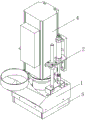
FIG. 1 is a schematic view of the whole dust removing apparatus according to the present invention;
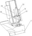
FIG. 2 is a schematic view of the lifting device of the present invention;
FIG. 3 is a schematic view of the blowing unit according to the present invention;
FIG. 4 is a schematic view of the interior of the dust removing apparatus according to the present invention;
in the figure: 1. the device comprises a main shaft dust hood, 2, a lifting device, 21, a lifting cylinder, 22, a cylinder support, 23, a sliding rail support, 24, a polished rod, 25, a linear bearing, 3, an air blowing unit, 31, an air blowing block, 32, an air blowing pipe, 33, an air blowing nozzle, 4, a main shaft cutter assembly, 5 and a brush.
Detailed Description
The technical solutions in the embodiments of the present application will be described clearly and completely with reference to the drawings in the embodiments of the present application, and it is obvious that the described embodiments are only a part of the embodiments of the present application, and not all of the embodiments. All other embodiments, which can be derived by a person skilled in the art from the embodiments of the present application without making any creative effort, shall fall within the protection scope of the present application.
In the description of the present invention, it is to be understood that the terms "front", "rear", "upper", "lower", "left", "right", and the like indicate orientations or positional relationships based on those shown in the drawings, and are only for convenience in describing the present invention and simplifying the description, but do not indicate or imply that the device or element referred to must have a specific orientation, be constructed in a specific orientation, and be operated, and thus, should not be construed as limiting the present invention.
As shown in figure 1, the invention discloses a dust removal device which mainly comprises a main shaft dust hood 1, a lifting device 2 and four air blowing units 3, wherein the main shaft dust hood 1 is sleeved on the outer wall of a main shaft cutter assembly 4 and is distributed coaxially with the main shaft cutter assembly. The cross section of the main shaft dust hood 1 is square, the lower end of the main shaft dust hood 1 is a quadrilateral dust collection port, four hairbrushes 5 are fixedly installed at the periphery of the dust collection port through bolts, and the four hairbrushes 5 form a closed area for surrounding a dust collection area.
As shown in fig. 2, the lifting device 2 includes two lifting units symmetrically distributed on the left and right side walls of the spindle tool assembly 4, each lifting unit includes a lifting cylinder 21, a cylinder support 22, a slide rail support 23 and a polish rod 24, the cylinder support 22 and the slide rail support 23 are fixed on the outer side wall of the spindle tool assembly 4 through bolt assemblies, the housing of the lifting cylinder 21 is fixed on the cylinder support 22, the movable end of the lifting cylinder 21 is fixedly connected with the top of the spindle dust hood 1 through a connecting piece, a linear bearing 25 is installed on the slide rail support 23, the upper end of the polish rod 24 is slidably sleeved in the linear bearing 25, and the lower end of the polish rod 24 is fixedly connected with the top surface of the spindle dust hood 1. The lifting cylinder 21 is connected with an air source through a cylinder joint, and when the lifting cylinder 21 drives the main shaft dust hood 1 to lift, the stable up-and-down lifting can be ensured through the matching of the polished rod 24.
As shown in fig. 3-4, an annular blowing fixing plate is mounted on the top of the spindle dust hood 1 through a bolt assembly, and four blowing units 3 are mounted on the blowing fixing plate and located in four directions of the spindle tool assembly 4X +, X-, Y +, Y-. Each air blowing unit 3 comprises an air blowing block 31, an air blowing pipe 32 and an air blowing nozzle 33, a long strip hole is processed on the air blowing fixing plate, the air blowing block 31 is correspondingly installed in the long strip hole through a nut, and the distance between the air blowing block 31 and a cutter can be adjusted through the design of the long strip hole. The upper end of the air blowing pipe 32 is a threaded pipe, the air blowing pipe is connected to an air outlet at the lower end of the air blowing block 31 through threads of the threaded pipe, the relative height of the air blowing pipe 32 is changed by adjusting the access depth of the threaded pipe, the air blowing nozzle 33 is communicated with the lower end of the air blowing pipe 32, and the air blowing nozzle 33 of the air blowing unit 3 is ensured to face towards the lower end of the cutter of the main shaft cutter assembly 4. Each air-vent block is communicated with an air source through an air pipe with an electromagnetic valve, and whether the air-vent block 31 is ventilated or not is controlled through the electromagnetic valve.
Taking the example of processing the wood board by using the engraving machine, the included angle between the axial lead of the blowing nozzle of each blowing unit and the axial lead of the main shaft cutter assembly is 30 degrees, and the distance between the air flow blown out by the blowing unit and the cutter on the XY plane is 15 mm. The dust removal method of the plate processing center comprises the following steps:
(1) the main shaft cutter assembly moves to a position to be processed on the surface of the plate, and the main shaft dust hood is controlled to descend by the lifting device until a dust collection port of the main shaft dust hood contacts the upper surface of the plate;
(2) the tool of the main shaft tool assembly starts to operate, the main shaft dust hood starts to work to discharge dust scraps on the surface of the plate, the air blowing unit starts to work, and the air pressure of the air blowing unit is 0.6-0.8 MPa;
when the cutter processes the plate along the X + direction, the ventilation block of the blowing unit positioned in the X-direction is switched on, and blown air flow enters the cutter diameter gap to blow up the chips;
when the cutter processes the plate along the X-direction, the ventilation block of the blowing unit positioned in the X + direction is switched on, and blown air flow enters the cutter diameter gap to blow up the chips;
when the cutter processes the plate along the Y + direction, the ventilation block of the blowing unit positioned in the Y-direction is switched on, and blown air flow enters the cutter diameter gap to blow up the chips;
when the cutter processes the plate along the Y-direction, the ventilation block of the blowing unit positioned in the Y + direction is switched on, and blown airflow enters the cutter diameter gap to blow up the chips;
(3) the scraps blown from the gap of the blade diameter of the plate are finally sucked away by the main shaft dust hood.
Through the steps, the dust removal method for the plate machining center can effectively clean the powdery scraps in the gap of the cutter diameter, solves the problem that dust in the gap of the cutter cannot be removed by a dust hood in the cutting process of the plate in the woodworking industry in the prior art, improves the integral dust collection effect in the cutting process, avoids secondary pollution in the blanking process, and ensures the plate machining precision.
It should be noted that the present invention is applicable not only to wood boards, but also to lightweight metal boards, such as aluminum boards, because powder chips can stay in the gap of the blade diameter when such boards are processed.
Claims (7)
1. The dust removal method for the plate processing center is characterized by comprising a liftable main shaft dust hood, wherein the main shaft dust hood is sleeved on the periphery of a main shaft cutter assembly, and air blowing units are respectively arranged in the main shaft dust hood in the X +, X-, Y + and Y-directions of the main shaft cutter assembly;
the dust removal method comprises the following steps:
(1) the main shaft cutter assembly moves to a position to be processed on the surface of the plate, and the main shaft dust hood descends until a dust collection port of the main shaft dust hood contacts the upper surface of the plate;
(2) starting to operate the cutter of the main shaft cutter assembly;
when the cutter processes the plate along the X + direction, the air blowing unit positioned in the X-direction blows air flow into the cutter diameter gap to blow up the scraps;
when the cutter processes the plate along the X-direction, the air blowing unit positioned in the X + direction blows air flow into the cutter diameter gap to blow up the scraps;
when the cutter processes the plate along the Y + direction, the blowing unit positioned in the Y-direction blows airflow into the cutter diameter gap to blow up chips;
when the cutter processes the plate along the Y-direction, the blowing unit positioned in the Y + direction blows air flow into the cutter diameter gap to blow up the scraps;
(3) the scraps blown from the gap of the blade diameter of the plate are sucked away by the main shaft dust hood.
2. The dust removal method for the plate processing center according to claim 1, wherein an included angle between the axis of the blowing nozzle of each blowing unit and the axis of the main shaft tool assembly is 30-45 °, and the distance between the air flow blown out by the blowing unit and the tool on the XY plane is 10-20 mm.
3. The dust removing method of a plate processing center according to claim 1, wherein the air pressure of the air blowing unit is 0.6 to 0.8 MPa.
4. The dust removal device suitable for the dust removal method of the plate machining center of claim 1 is characterized by comprising a main shaft dust hood, wherein the main shaft dust hood is sleeved on the outer wall of a main shaft cutter assembly, and a lifting device is arranged between the main shaft dust hood and the main shaft cutter assembly and can enable the main shaft dust hood to move up and down;
and air blowing units are respectively arranged in the main shaft dust hood in the X +, X-, Y + and Y-directions of the main shaft cutter assembly, and air blowing nozzles of all the air blowing units face the lower end of the cutter of the main shaft cutter assembly.
5. The dust removing device of claim 4, wherein the cross section of the main shaft dust hood is square, the lower end of the main shaft dust hood is a quadrangular dust suction port, and a brush capable of surrounding a dust suction area is arranged at the peripheral position of the dust suction port;
the spindle dust hood is characterized in that a blowing fixing plate is arranged at the inner top of the spindle dust hood, a blowing unit comprises a ventilation block, a blowing pipe and a blowing nozzle, the ventilation block is fixed on the blowing fixing plate, the upper end of the blowing pipe is in threaded connection with the lower end of the ventilation block, and the blowing nozzle is communicated with the lower end of the blowing pipe.
6. The dust removing apparatus of claim 5, wherein the lifting means comprises two lifting units symmetrically disposed on left and right side walls of the spindle tool assembly.
7. The dust removing apparatus of claim 6, wherein each lifting unit comprises a lifting cylinder and a cylinder support, the cylinder support is fixed on the outer wall of the spindle tool assembly, a housing of the lifting cylinder is fixed on the cylinder support, and a movable end of the lifting cylinder is fixedly connected with the top surface of the spindle dust hood.
Priority Applications (1)
| Application Number | Priority Date | Filing Date | Title |
|---|---|---|---|
| CN202111354236.1A CN114043586A (en) | 2021-11-16 | 2021-11-16 | Dust removal method and dust removal device for plate processing center |
Applications Claiming Priority (1)
| Application Number | Priority Date | Filing Date | Title |
|---|---|---|---|
| CN202111354236.1A CN114043586A (en) | 2021-11-16 | 2021-11-16 | Dust removal method and dust removal device for plate processing center |
Publications (1)
| Publication Number | Publication Date |
|---|---|
| CN114043586A true CN114043586A (en) | 2022-02-15 |
Family
ID=80209612
Family Applications (1)
| Application Number | Title | Priority Date | Filing Date |
|---|---|---|---|
| CN202111354236.1A Pending CN114043586A (en) | 2021-11-16 | 2021-11-16 | Dust removal method and dust removal device for plate processing center |
Country Status (1)
| Country | Link |
|---|---|
| CN (1) | CN114043586A (en) |
Cited By (1)
| Publication number | Priority date | Publication date | Assignee | Title |
|---|---|---|---|---|
| CN118061305A (en) * | 2024-02-21 | 2024-05-24 | 上海维宏电子科技股份有限公司 | Method, device, processor and computer readable storage medium for realizing intelligent square blowing operation of cutting based on motion control system |
Citations (5)
| Publication number | Priority date | Publication date | Assignee | Title |
|---|---|---|---|---|
| CN210820025U (en) * | 2019-08-26 | 2020-06-23 | 南京帝鼎数控科技有限公司 | Dust hood with external blowing structure |
| CN210880079U (en) * | 2019-08-26 | 2020-06-30 | 南京帝鼎数控科技有限公司 | A dust collector for woodworking cutting center |
| CN211137496U (en) * | 2019-04-12 | 2020-07-31 | 南兴装备股份有限公司 | Main shaft blowing and dust removing mechanism of numerical control equipment, main shaft machining device and machine head |
| CN211566206U (en) * | 2019-10-28 | 2020-09-25 | 广东万恒通家居制品有限公司 | Automatic blowing chip removal machining spindle for furniture carving |
| CN211640290U (en) * | 2019-12-25 | 2020-10-09 | 广州市艾依格家居制品有限公司 | Dust collector in big board suit cutting |
-
2021
- 2021-11-16 CN CN202111354236.1A patent/CN114043586A/en active Pending
Patent Citations (5)
| Publication number | Priority date | Publication date | Assignee | Title |
|---|---|---|---|---|
| CN211137496U (en) * | 2019-04-12 | 2020-07-31 | 南兴装备股份有限公司 | Main shaft blowing and dust removing mechanism of numerical control equipment, main shaft machining device and machine head |
| CN210820025U (en) * | 2019-08-26 | 2020-06-23 | 南京帝鼎数控科技有限公司 | Dust hood with external blowing structure |
| CN210880079U (en) * | 2019-08-26 | 2020-06-30 | 南京帝鼎数控科技有限公司 | A dust collector for woodworking cutting center |
| CN211566206U (en) * | 2019-10-28 | 2020-09-25 | 广东万恒通家居制品有限公司 | Automatic blowing chip removal machining spindle for furniture carving |
| CN211640290U (en) * | 2019-12-25 | 2020-10-09 | 广州市艾依格家居制品有限公司 | Dust collector in big board suit cutting |
Cited By (1)
| Publication number | Priority date | Publication date | Assignee | Title |
|---|---|---|---|---|
| CN118061305A (en) * | 2024-02-21 | 2024-05-24 | 上海维宏电子科技股份有限公司 | Method, device, processor and computer readable storage medium for realizing intelligent square blowing operation of cutting based on motion control system |
Similar Documents
| Publication | Publication Date | Title |
|---|---|---|
| CN106217114B (en) | A kind of comprehensive processing dust absorption nozzles of CNC | |
| CN201776492U (en) | An environment-friendly CNC engraving and milling machine | |
| CN215317360U (en) | Gantry type milling machine with dustproof function | |
| CN110525097B (en) | Foam carving machine | |
| CN211252012U (en) | Self-cleaning formula engraver | |
| CN216263676U (en) | Five four milling cutter end milling machines of environment-friendly numerical control | |
| CN216268410U (en) | Novel high-efficient stable cnc engraving and milling machine | |
| CN214604874U (en) | Machining center with plate table-board dust-absorption blowing device | |
| CN209754697U (en) | Multilayer engraving and milling machine with dust removal cleaning device | |
| CN113427310B (en) | Planer-type milling machine with dustproof function | |
| CN211640290U (en) | Dust collector in big board suit cutting | |
| CN211277551U (en) | Row type tool changing machining center | |
| CN210820025U (en) | Dust hood with external blowing structure | |
| CN116276273A (en) | Dustproof lathe | |
| CN217513480U (en) | Cnc engraving and milling machine with dust keeper | |
| CN217256866U (en) | 360 degree automatic rotation CNC saw | |
| CN217552620U (en) | Shaving board processing is with inhaling bits edulcoration device | |
| CN113878150B (en) | Environment-friendly numerical control five-axis four-milling cutter end face milling machine | |
| CN211028277U (en) | Chip suction device of numerical control milling machine | |
| CN213859709U (en) | Woodworking flat planer with collect saw-dust function | |
| CN219967263U (en) | Machining platform and machining machine tool | |
| CN220007008U (en) | Chamfering milling machine | |
| CN222096409U (en) | Dust removal device for woodworking engraving machine | |
| CN223702138U (en) | Numerical control processing machine for glass relief | |
| CN217494464U (en) | Environment-friendly plate cutting machine |
Legal Events
| Date | Code | Title | Description |
|---|---|---|---|
| PB01 | Publication | ||
| PB01 | Publication | ||
| SE01 | Entry into force of request for substantive examination | ||
| SE01 | Entry into force of request for substantive examination | ||
| RJ01 | Rejection of invention patent application after publication | ||
| RJ01 | Rejection of invention patent application after publication |
Application publication date: 20220215 |