Adjustable clamping device and clamping method for welding large rack
Technical Field
The invention relates to the technical field of rack welding, in particular to an adjustable clamping device and a clamping method for large rack welding.
Background
The frame is used for bearing the mechanical shelf, some frames are made of stainless steel, in the manufacturing process of the frame, some parts of the frame need to be welded together, so that the frame forms a relatively complete main body and can better bear mechanical parts;
the adjustable clamping device and the clamping method for welding the large-scale rack have the advantages that the large-scale rack is clamped from two sides through the clamping plates, when the welding position of the rack is changed, workers need to rotate around the rack part continuously to weld the rack part better, manpower is wasted, the clamping plates are fixed in the moving positions, different positions of the rack cannot be clamped well, welding quality is reduced easily due to looseness during welding operation, and therefore the adjustable clamping device and the clamping method for welding the large-scale rack are provided.
Disclosure of Invention
In view of the above, it is desirable to provide an adjustable clamping device and a clamping method for welding a large rack, so as to solve or alleviate the technical problems in the prior art, and to provide at least one useful choice.
The technical scheme of the embodiment of the invention is realized as follows: an adjustable clamping device for welding of large racks, comprising:
a base assembly including a table and a turntable;
the top of the workbench is provided with a turntable;
the sliding assembly comprises linear sliding grooves, annular sliding grooves and sliding blocks, eight linear sliding grooves are distributed at the top of the rotary table at equal intervals, the annular sliding grooves are formed in the edge of the top of the rotary table, the eight linear sliding grooves are communicated with one side, adjacent to and in contact with the annular sliding grooves, and the eight linear sliding grooves are embedded in the eight linear sliding grooves and are connected with the four sliding blocks in a sliding mode;
the adjusting and clamping assembly comprises a rotating rod, a fixing block, a first threaded rod, a V-shaped clamping plate, a second threaded rod and a flat clamping plate;
the horizontal and vertical all run through and threaded connection of fixed block has first threaded rod and second threaded rod, the one end fixedly connected with V type splint of first threaded rod, the one end fixedly connected with flat splint of second threaded rod.
Further preferably, both sides of the bottom of the workbench are fixedly connected with supporting plates, and a driving assembly is arranged at the bottom of the workbench.
Further preferably, the driving assembly comprises a motor, a central shaft and a fixing plate;
the bottom of workstation is through two fixed plate fixedly connected with motors, the output shaft fixedly connected with center pin of motor, the lateral wall of center pin runs through and rotates through the bearing and connect in the interior middle part of workstation, the one end fixed connection of center pin is in the bottom of carousel.
Further preferably, the top of each of the four sliding blocks is fixedly connected with an electric cylinder, a piston rod of each electric cylinder is fixedly connected with a rotating rod, and one end, far away from the electric cylinder, of each rotating rod is connected to the bottom of the corresponding fixed block in a threaded mode.
Preferably, the two sides of the electric cylinder are provided with limiting assemblies, and each limiting assembly comprises a pipe body, a rod body, a limiting block and a foot pad;
two body fixed connection in the spacing subassembly are in the both sides of electric jar, the inside wall threaded connection of body has the body of rod, the bottom fixedly connected with stopper of the body of rod.
Further preferably, the top fixedly connected with knob of the body of rod, the bottom of stopper bonds there is the callus on the sole.
Preferably, the outer side wall of the V-shaped clamping plate is bonded with a V-shaped damping pad, and the outer side wall of the flat clamping plate is bonded with a flat damping pad.
Further preferably, a controller is installed on one side of the top of the workbench, and an electrical output end of the controller is electrically connected with electrical input ends of the electric cylinder and the motor through wires.
The invention provides an adjustable clamping method for welding a large rack, which comprises the following steps:
adjusting a clamping assembly to be adjusted to the positions of any linear sliding groove and any annular sliding groove under the driving of a sliding block;
step two, the knob drives the rod body to rotate in the pipe body by rotating the knob, and then the limiting block moves towards the turntable;
thirdly, the controller controls the motor to start, an output shaft of the motor drives the central shaft to rotate, and the central shaft drives the turntable to rotate under the action of the bearing;
fourthly, the piston rod of the electric cylinder can drive the fixing block to move upwards, flat clamping plates and V-shaped clamping plates are arranged on the upper layer and the lower layer of the fixing block, and the frame in irregular and round positions is clamped and fixed through the V-shaped part of the V-shaped clamping plate;
and fifthly, the fixing block is rotated to change the clamping positions of the flat clamping plate and the V-shaped clamping plate, and the contact distances between the flat clamping plate and the rack and the contact distances between the V-shaped clamping plate and the rack can be respectively adjusted by rotating the first threaded rod and the second threaded rod.
Due to the adoption of the technical scheme, the embodiment of the invention has the following advantages:
1. according to the invention, the eight linear sliding grooves and the eight annular sliding grooves are arranged, so that the adjusting and clamping assembly can be driven by the sliding block to be adjusted to any position of the linear sliding grooves and the annular sliding grooves, the shape and the direction of the rack can be changed to the clamping angle position, the driving assembly can drive the turntable to rotate, the position of the adjusting and clamping assembly after being fixed can be finely adjusted and rotated, and the phenomenon that more manpower is wasted for welding around the rack is avoided;
2. the clamping height can be adjusted through the electric cylinder, the flat clamping plate and the V-shaped clamping plate can clamp and fix the positions of the plane part, the irregular part and the round rack, the clamping positions of the flat clamping plate and the V-shaped clamping plate are changed through rotating the fixing block, and the contact distances between the flat clamping plate and the rack and between the V-shaped clamping plate and the rack can be respectively adjusted through rotating the first threaded rod and the second threaded rod.
The foregoing summary is provided for the purpose of description only and is not intended to be limiting in any way. In addition to the illustrative aspects, embodiments, and features described above, further aspects, embodiments, and features of the present invention will be readily apparent by reference to the drawings and following detailed description.
Drawings
In order to more clearly illustrate the embodiments of the present application or the technical solutions in the prior art, the drawings needed to be used in the embodiments or technical descriptions will be briefly described below, it is obvious that the drawings in the following description are only some embodiments of the present application, and for those skilled in the art, other drawings can be obtained according to the drawings without creative efforts.
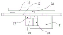
FIG. 1 is a block diagram of the present invention;
FIG. 2 is a block diagram of the glide assembly of the present invention;
FIG. 3 is a block diagram of the drive assembly of the present invention;
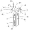
FIG. 4 is a perspective view of the adjustable clamp assembly of the present invention;
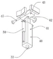
FIG. 5 is a view of another perspective of the adjustable clamp assembly of the present invention.
Reference numerals: 10. a base assembly; 11. a support plate; 12. a work table; 13. a turntable; 14. a controller; 20. a drive assembly; 21. a motor; 22. a central shaft; 23. a fixing plate; 30. a slipping component; 31. a linear chute; 32. an annular chute; 33. a slider; 40. adjusting the clamping assembly; 41. an electric cylinder; 42. a rotating rod; 43. a fixed block; 44. a first threaded rod; 45. a V-shaped splint; 46. a V-shaped damping pad; 47. a second threaded rod; 48. a flat splint; 49. a flat damping pad; 50. a limiting component; 51. a pipe body; 52. a rod body; 53. a limiting block; 54. a foot pad; 55. a knob.
Detailed Description
In the following, only certain exemplary embodiments are briefly described. As those skilled in the art will recognize, the described embodiments may be modified in various different ways, all without departing from the spirit or scope of the present invention. Accordingly, the drawings and description are to be regarded as illustrative in nature, and not as restrictive.
Embodiments of the present invention will be described in detail below with reference to the accompanying drawings.
As shown in fig. 1 to 5, an embodiment of the present invention provides an adjustable clamping device for welding a large rack, including:
a base assembly 10, the base assembly 10 including a table 12 and a turntable 13;
a rotary table 13 is arranged at the top of the workbench 12;
the sliding assembly 30 comprises a linear sliding chute 31, an annular sliding chute 32 and sliding blocks 33, eight linear sliding chutes 31 are equidistantly distributed on the top of the rotary table 13, the annular sliding chute 32 is arranged at the edge of the top of the rotary table 13, the eight linear sliding chutes 31 are communicated with one side of the annular sliding chute 32, which is in adjacent contact with the eight linear sliding chutes 31, and the four sliding blocks 33 are embedded and slidably connected in the eight linear sliding chutes 31;
the adjusting and clamping assembly 40 is characterized in that the adjusting and clamping assembly 40 comprises a rotating rod 42, a fixed block 43, a first threaded rod 44, a V-shaped clamping plate 45, a second threaded rod 47 and a flat clamping plate 48;
the fixing block 43 is transversely and longitudinally penetrated and in threaded connection with a first threaded rod 44 and a second threaded rod 47, one end of the first threaded rod 44 is fixedly connected with a V-shaped clamping plate 45, and one end of the second threaded rod 47 is fixedly connected with a flat clamping plate 48.
In one embodiment, the supporting plates 11 are fixedly connected to both sides of the bottom of the working table 12, the driving assembly 20 is disposed at the bottom of the working table 12, the invention is supported by the supporting plates 11, and the rotating disc 13 is driven to rotate by the driving assembly 20.
In one embodiment, the drive assembly 20 includes a motor 21, a central shaft 22, and a fixed plate 23;
the bottom of workstation 12 is through two fixed plate 23 fixedly connected with motors 21, motor 21's output shaft fixedly connected with center pin 22, center pin 22's lateral wall runs through and rotates through the bearing and connect in the interior middle part of workstation 12, center pin 22's one end fixed connection is in the bottom of carousel 13, fix motor 21 through fixed plate 23, rotate through controller 14 control motor 21, motor 21 drives center pin 22 and rotates, center pin 22 drives carousel 13 and rotates.
In one embodiment, an electric cylinder 41 is fixedly connected to the tops of the four sliding blocks 33, a rotating rod 42 is fixedly connected to a piston rod of the electric cylinder 41, one end, far away from the electric cylinder 41, of the rotating rod 42 is in threaded connection with the bottom of a fixed block 43, the clamping height of the adjusting clamping assembly 40 is adjusted through the electric cylinder 41, and the fixed block 43 can be rotated and fixed through threads with the rotating rod 42 through threaded connection of the rotating rod 42 with the bottom of the fixed block 43.
In one embodiment, the electric cylinder 41 is provided with a limiting assembly 50 on both sides, and the limiting assembly 50 includes a tube 51, a rod 52, a limiting block 53 and a foot pad 54;
two body 51 fixed connection in two spacing subassemblies 50 are in the both sides of electric jar 41, and the inside wall threaded connection of body 51 has the body of rod 52, and the bottom fixedly connected with stopper 53 of the body of rod 52 is adjusted the position of adjusting clamping component 40 after, is fixed adjusting clamping component 40 on contacting the chassis by stopper 53 and callus on the sole 54.
In one embodiment, the knob 55 is fixedly connected to the top of the rod 52, the foot pad 54 is bonded to the bottom of the limiting block 53, the friction force between the limiting block 53 and the rotary table 13 is improved through the foot pad 54, and the fixing effect is improved.
In one embodiment, the V-shaped damping pad 46 is adhered to the outer side wall of the V-shaped clamp plate 45, the flat damping pad 49 is adhered to the outer side wall of the flat clamp plate 48, and friction force when the frame is clamped is increased through the V-shaped damping pad 46 and the flat damping pad 49, so that the clamping effect is improved.
In one embodiment, a controller 14 is installed on one side of the top of the working platform 12, an electrical output terminal of the controller 14 is electrically connected to electrical input terminals of the electric cylinder 41 and the motor 21 through a wire, and the controller 14 controls the electric cylinder 41 and the motor 21 to be turned on and off.
The invention provides an adjustable clamping method for welding a large rack, which comprises the following steps:
firstly, adjusting the clamping assembly 40 to be adjusted to the positions of any linear sliding chute 31 and any annular sliding chute 32 under the driving of the sliding block 33;
step two, by rotating the knob 55, the knob 55 drives the rod body 52 to rotate inside the tube body 51, so that the limiting block 53 moves towards the rotary table 13;
step three, the controller 14 controls the motor 21 to start, the output shaft of the motor 21 drives the central shaft 22 to rotate, and the central shaft 22 drives the rotary table 13 to rotate under the action of the bearing;
step four, the piston rod of the electric cylinder 41 can drive the fixing block 43 to move upwards, the upper layer and the lower layer of the fixing block 43 are provided with a flat clamping plate 48 and a V-shaped clamping plate 45, and the rack at the irregular and round positions is clamped and fixed through the V-shaped part of the V-shaped clamping plate 45;
and step five, the fixing block 43 is rotated to change the clamping positions of the flat clamping plate 48 and the V-shaped clamping plate 45, and the contact distances between the flat clamping plate 48 and the rack and the V-shaped clamping plate 45 can be respectively adjusted by rotating the first threaded rod 44 and the second threaded rod 47.
The invention specifically works as follows: the invention can adjust the clamping component 40 to any position of the straight sliding chute 31 and the annular sliding chute 32 under the drive of the sliding block 33 by arranging the eight straight sliding chutes 31 and the annular sliding chute 32, further change the clamping position through the size shape and the direction of the frame, after sliding, the knob 55 can drive the rod body 52 to rotate in the tube body 51 by rotating the knob 55, further move the limit block 53 to the rotary table 13, make the foot pad 54 contact the top of the rotary table 13 and fasten, further limit the clamping component 40 to the position of the rotary table 13, and can control the motor 21 to start by the controller 14, the output shaft of the motor 21 drives the central shaft 22 to rotate, the rotary table 13 is driven by the central shaft 22 to rotate under the action of the bearing, further fine adjustment can be carried out on the position after the clamping component 40 is fixed, the precision during clamping is improved, the fixed block 43 can be driven to move upwards by the piston rod of the electric cylinder 41, and then adjust the height that presss from both sides tightly, there are flat splint 48 and V-arrangement splint 45 on the lower floor of fixed block 43, and then fix the plane department of frame through flat splint 48, press from both sides the frame department of fixing irregular and circular position through the V-arrangement portion of V-arrangement splint 45, change the position of flat splint 48 and V-arrangement splint 45 centre gripping through rotating fixed block 43, can adjust the contact interval of flat splint 48 and V-arrangement splint 45 and frame respectively through rotating first threaded rod 44 and second threaded rod 47, the invention can clamp the frame fixedly by the regulation of diversified and angle, the accuracy when having improved the frame welding, prevent its skew.
The above description is only for the specific embodiment of the present invention, but the scope of the present invention is not limited thereto, and any person skilled in the art can easily conceive various changes or substitutions within the technical scope of the present invention, and these should be covered by the scope of the present invention. Therefore, the protection scope of the present invention shall be subject to the protection scope of the appended claims.