CN114027850A - Wire arranging device for electrocardio monitoring - Google Patents
Wire arranging device for electrocardio monitoring Download PDFInfo
- Publication number
- CN114027850A CN114027850A CN202111298115.XA CN202111298115A CN114027850A CN 114027850 A CN114027850 A CN 114027850A CN 202111298115 A CN202111298115 A CN 202111298115A CN 114027850 A CN114027850 A CN 114027850A
- Authority
- CN
- China
- Prior art keywords
- clamping
- wire
- line
- arranging device
- ring
- Prior art date
- Legal status (The legal status is an assumption and is not a legal conclusion. Google has not performed a legal analysis and makes no representation as to the accuracy of the status listed.)
- Withdrawn
Links
- 238000012544 monitoring process Methods 0.000 title claims abstract description 13
- 230000001788 irregular Effects 0.000 claims description 3
- 230000003044 adaptive effect Effects 0.000 abstract 1
- 238000010586 diagram Methods 0.000 description 7
- 239000000243 solution Substances 0.000 description 4
- WABPQHHGFIMREM-UHFFFAOYSA-N lead(0) Chemical compound [Pb] WABPQHHGFIMREM-UHFFFAOYSA-N 0.000 description 2
- 238000000034 method Methods 0.000 description 2
- 230000000202 analgesic effect Effects 0.000 description 1
- QVGXLLKOCUKJST-UHFFFAOYSA-N atomic oxygen Chemical compound [O] QVGXLLKOCUKJST-UHFFFAOYSA-N 0.000 description 1
- 230000009286 beneficial effect Effects 0.000 description 1
- 238000005516 engineering process Methods 0.000 description 1
- 238000001746 injection moulding Methods 0.000 description 1
- 239000007788 liquid Substances 0.000 description 1
- 238000012986 modification Methods 0.000 description 1
- 230000004048 modification Effects 0.000 description 1
- 238000012806 monitoring device Methods 0.000 description 1
- 229910052760 oxygen Inorganic materials 0.000 description 1
- 239000001301 oxygen Substances 0.000 description 1
Images






Classifications
-
- A—HUMAN NECESSITIES
- A61—MEDICAL OR VETERINARY SCIENCE; HYGIENE
- A61B—DIAGNOSIS; SURGERY; IDENTIFICATION
- A61B5/00—Measuring for diagnostic purposes; Identification of persons
- A61B5/24—Detecting, measuring or recording bioelectric or biomagnetic signals of the body or parts thereof
- A61B5/316—Modalities, i.e. specific diagnostic methods
- A61B5/318—Heart-related electrical modalities, e.g. electrocardiography [ECG]
- A61B5/321—Accessories or supplementary instruments therefor, e.g. cord hangers
-
- H—ELECTRICITY
- H02—GENERATION; CONVERSION OR DISTRIBUTION OF ELECTRIC POWER
- H02G—INSTALLATION OF ELECTRIC CABLES OR LINES, OR OF COMBINED OPTICAL AND ELECTRIC CABLES OR LINES
- H02G3/00—Installations of electric cables or lines or protective tubing therefor in or on buildings, equivalent structures or vehicles
- H02G3/30—Installations of cables or lines on walls, floors or ceilings
- H02G3/32—Installations of cables or lines on walls, floors or ceilings using mounting clamps
Landscapes
- Health & Medical Sciences (AREA)
- Life Sciences & Earth Sciences (AREA)
- Engineering & Computer Science (AREA)
- Biomedical Technology (AREA)
- Medical Informatics (AREA)
- Cardiology (AREA)
- Physics & Mathematics (AREA)
- Civil Engineering (AREA)
- Biophysics (AREA)
- Pathology (AREA)
- Architecture (AREA)
- Heart & Thoracic Surgery (AREA)
- Structural Engineering (AREA)
- Molecular Biology (AREA)
- Surgery (AREA)
- Animal Behavior & Ethology (AREA)
- General Health & Medical Sciences (AREA)
- Public Health (AREA)
- Veterinary Medicine (AREA)
- Measurement And Recording Of Electrical Phenomena And Electrical Characteristics Of The Living Body (AREA)
Abstract
The invention discloses a wire arranging device for monitoring various electrocardios in the technical field of medical equipment, which comprises a plurality of wire bodies and a plurality of wire arranging devices for intensively arranging the wire bodies. The wire arranging device comprises a plurality of wire clamps used for clamping a wire body, each wire clamp comprises a clamping body used for clamping the wire body, and a screw and a nut are mounted on each clamping body. The clamp body comprises a clamping ring which is in a circular ring shape and is used for clamping a wire body, the middle of the wall surface at the right lower side of the clamping ring is connected with a clamping head, and the wall surface at the left lower side of the clamping ring is connected with two clamping tails which are symmetrically distributed front and back. The adaptive line card can be manually selected to be clamped on the line body. And according to the number of the line bodies, selecting the line cards with the same number to be connected end to form a line arranging device, and bundling all the line bodies together. After all the line bodies are bundled and arranged together, the line bodies are prevented from being scattered around the body of a patient, and further inconvenience caused by the scattered line bodies is avoided.
Description
Technical Field
The invention relates to the technical field of medical equipment, in particular to a wire arranging device for electrocardio monitoring.
Background
Many patients are treated by hospital department, some patients need medical equipment such as an ECG monitor and oxygen supply equipment, and the equipment is provided with a power line, and when the equipment is used, a plug of the power line needs to be inserted into a socket near a sickbed to electrify the equipment.
Besides the power cord, the general ECG monitor also has three lead wires, one end of which is inserted on the monitoring device and the other end is connected with an electrode plate for sticking on the body of the patient.
No matter the power line or the lead wire is scattered around the patient during the use of the equipment, the patient is easy to touch the wire bodies during the process of turning over the body, the action of the patient is hindered, and particularly when medical equipment such as a flow guide pipe, a liquid conveying pipe, an analgesic rod and the like are arranged on the patient body, attention needs to be paid to avoid the entanglement of the patient body with the power line and the lead wire during the process of turning over the body. In addition, when the doctor turns over and inspects the body of the patient, the line bodies scattered around the patient hinder the examination of the doctor.
Based on the wire arranging device, the wire arranging device for electrocardio monitoring is designed, and can be used for bundling and arranging power wires and lead wires so as to solve the problem of wire body scattering.
Disclosure of Invention
The invention aims to provide a wire arranging device for electrocardio monitoring, which solves the problem of the scattered wire bodies of power wires and lead wires in the background technology.
In order to achieve the purpose, the invention provides the following technical scheme: the utility model provides an electrocardio is whole line ware for control, includes a plurality of line body, a plurality of install the whole line ware that a plurality of was used for concentrating the arrangement to the line body on a plurality of the line body.
The wire arranging device comprises a plurality of wire clamps used for clamping a wire body, each wire clamp comprises a clamping body used for clamping the wire body, and a screw and a nut are mounted on each clamping body.
The clamp body comprises a clamp ring which is in a circular ring shape and is used for clamping a wire body, the middle of the wall surface at the right lower side of the clamp ring is connected with a clamp head, and the wall surface at the left lower side of the clamp ring is connected with two clamp tails which are symmetrically distributed front and back.
The screw and the nut are arranged on the clamping tail.
Preferably, a plurality of the line cards are sequentially connected end to form an irregular closed-loop line arranging device, and the number of the line cards in the line arranging device is at least three.
Preferably, the top ring body of the snap ring is provided with a notch for clamping the wire body into the snap ring cavity.
Preferably, the clamping head is in a circular ring shape, and a notch is formed in the right lower ring body of the clamping head.
Preferably, a straight line from the center of the chuck to the center of the snap ring connected with the chuck intersects with a symmetry axis of the snap ring to form an included angle of 60 degrees.
Preferably, the clamping tails are circular, and the screw penetrates through the two clamping tails and is fastened and screwed with the nut.
Preferably, a straight line from a midpoint of a line segment formed by connecting centers of two card tail hole cavities in the same card body to a circle center of a snap ring connected with the card tail intersects with a symmetry axis of the snap ring to form an included angle of 60 degrees.
Compared with the prior art, the invention has the beneficial effects that:
according to the diameter of different line bodies, the invention can manually select the line cards matched with each other to be clamped on the line bodies. And according to the number of the line bodies, selecting the line cards with the same number to be connected end to form a line arranging device, and bundling all the line bodies together. After all the line bodies are bundled and arranged together, the line bodies are prevented from being scattered around the body of a patient, and further inconvenience caused by the scattered line bodies is avoided.
Of course, it is not necessary for any product in which the invention is practiced to achieve all of the above-described advantages at the same time.
Drawings
In order to more clearly illustrate the technical solutions of the embodiments of the present invention, the drawings used in the description of the embodiments will be briefly introduced below, and it is obvious that the drawings in the following description are only some embodiments of the present invention, and it is obvious for those skilled in the art that other drawings can be obtained according to the drawings without creative efforts.
FIG. 1 is a schematic view of the present invention;
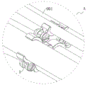
FIG. 2 is an enlarged view taken at A of FIG. 1 in accordance with the present invention;
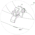
FIG. 3 is an enlarged view of FIG. 1 at B according to the present invention;
FIG. 4 is an enlarged view of FIG. 1 at C according to the present invention;
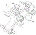
fig. 5 is a first structural schematic diagram of an organizer composed of five line cards according to the present invention;
fig. 6 is a structural schematic diagram of a wire arranging device composed of five wire cards according to the present invention;
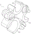
fig. 7 is a first structural schematic diagram of a wire arrangement device composed of three wire cards according to the present invention;
fig. 8 is a structural schematic diagram of a wire arranging device composed of three wire cards according to the present invention;
FIG. 9 is a diagram of a first line card structure according to the present invention;
FIG. 10 is a diagram of a second line card structure according to the present invention;
FIG. 11 is an exploded view of the configuration of a line card of the present invention;
FIG. 12 is a schematic view of a card body according to the present invention;
fig. 13 is a diagram of line cards of different specifications according to the present invention.
In the drawings, the components represented by the respective reference numerals are listed below:
001-wire body, 1-wire arranging device, 11-wire clip, 100-clamping body, 110-clamping ring, 120-clamping head, 130-clamping tail, 200-screw and 300-nut.
Detailed Description
The technical solutions in the embodiments of the present invention will be clearly and completely described below with reference to the drawings in the embodiments of the present invention, and it is obvious that the described embodiments are only a part of the embodiments of the present invention, and not all of the embodiments. All other embodiments, which can be derived by a person skilled in the art from the embodiments given herein without making any creative effort, shall fall within the protection scope of the present invention.
Referring to fig. 1-4, the present invention provides a technical solution of a wire arranging device for monitoring an electrocardiogram, including a plurality of wire arranging devices 1 mounted on wire bodies 001 and performing bundling and arranging on a plurality of wire bodies 001.
Referring to fig. 5 and 6, the wire arranging device 1 provided by the present invention is composed of five line cards 11 with different specifications for being clamped on the wire 001 in an end-to-end manner.
Referring to fig. 7 and 8, the wire arranging device 1 provided by the present invention is composed of three line cards 11 with different specifications, which are used to be clamped on the wire body 001, in an end-to-end manner.
Referring to fig. 9-11, the present invention provides a line card 11, which includes a card body 100 for being clamped on a line body 001, a screw 200 mounted on the card body 100, and a nut 300 engaged with the screw 200.
Referring to fig. 12 and 13, the clip body 100 of the present invention includes a circular ring-shaped clip ring 110 for clipping on the wire 001, and a notch is formed at the top of the clip ring 110 for clipping the wire 001 into the annular cavity of the clip ring 110.
The middle part of the right lower wall surface of the snap ring 110 is connected with a circular chuck 120, and the right lower part of the chuck 120 is provided with a notch.
The left lower wall surface of the ring body of the snap ring 110 is connected with two annular snap tails 130, and the two snap tails 130 are arranged in a front-back symmetrical manner.
In the same card body 100, the front wall surface of the front card tail 130 and the front wall surface of the snap ring 110 connected with the front card tail are in the same plane; the rear wall surface of the rear clip tail 130 is in the same plane as the rear wall surface of the clip ring 110 to which it is attached. The snap ring 100 is a component integrally formed by an injection molding process, and the snap ring 110, the chuck 120 and the clip tail 130 are different parts of the component respectively.
In the same line card 11, the screw 200 of the line card 11 passes through the holes of the two card tails 130 and then the nut 300 is screwed on, and after the nut 300 is screwed, the nut 300 and the screw 200 are fixedly mounted on the card tails 130.
In two adjacent line cards 11, the chuck 120 of the line card 11 located on the left is clamped on the screw 200 of the line card 11 located on the right, and the chuck 120 of the line card 11 on the left is located in the clamping cavity of the two clamping tails 130 of the line card 11 on the right, and the front wall surface and the rear wall surface of the chuck 120 are respectively in contact with the front wall surface and the rear wall surface of the clamping cavity of the two clamping tails 130.
In the line cards 11 with different specifications, the difference is that the diameters of the snap rings 110 are different, so that the line cards 11 which are matched with each other are selected to be clamped on the line bodies 001 according to the diameters of different line bodies 001.
In addition, according to the number of the line bodies 001, the line cards 11 with the same number are selected to be connected end to end in the above manner to form an irregular closed loop, so as to form the line arranging device 1. Each line body 001 is respectively clamped into the ring cavity of the clamping ring 110 of the line card 11 matched with the line body 001, so that the line arranging device 1 bundles the line bodies 001 together, and after the line bodies 001 are bundled and arranged together, the line bodies 001 are prevented from being scattered around the body of a patient,
in the foregoing, exemplary embodiments of the proposed solution have been described in detail with reference to preferred embodiments, however, it will be understood by those skilled in the art that many variations and modifications may be made to the specific embodiments described above, and that many combinations of the various features and structures presented in the present invention may be made without departing from the inventive concept, the scope of which is defined by the appended claims.
Claims (7)
1. The utility model provides an electrocardio is whole line ware for control, includes a plurality of root line bodies 001, its characterized in that: a plurality of wire arranging devices (1) for intensively arranging the wire bodies (001) are arranged on the plurality of wire bodies (001);
the wire arranging device (1) comprises a plurality of wire clamps (11) used for clamping the wire bodies (001), each wire clamp (11) comprises a clamping body (100) used for clamping the wire bodies (001), and each clamping body (100) is provided with a screw (200) and a nut (300);
the clamping body (100) comprises a circular clamping ring (110) used for clamping the wire body (001), the middle of the wall surface at the lower right of the clamping ring (110) is connected with a clamping head (120), and the wall surface at the lower left of the clamping ring (110) is connected with two clamping tails (130) which are symmetrically distributed in the front-back direction;
the screw (200) and the nut (300) are mounted on the clip tail (130).
2. The electrocardiograph monitoring wire arranging device according to claim 1, wherein: the line cards (11) are sequentially connected end to form an irregular closed-loop line arranging device (1), and the number of the line cards (11) in the line arranging device (1) is at least three.
3. The electrocardiograph monitoring wire arranging device according to claim 1, wherein: the top ring body of the snap ring (110) is provided with a notch for clamping the wire body (001) into the ring cavity of the snap ring (100).
4. The electrocardiograph monitoring wire arranging device according to claim 1, wherein: the clamping head (120) is in a circular ring shape, and a notch is formed in the right lower ring body of the clamping head (120).
5. The electrocardiograph monitoring wire arranging device according to claim 4, wherein: the straight line from the circle center of the chuck (120) to the circle center of the clamping ring (110) connected with the chuck is intersected with the symmetry axis of the clamping ring (110) to form an included angle of 60 degrees.
6. The electrocardiograph monitoring wire arranging device according to claim 1, wherein: the clamping tails (130) are annular, and the screw (200) penetrates through the two clamping tails (130) and is fastened and screwed with the nut (300).
7. The electrocardiograph monitoring wire arranging device according to claim 6, wherein: the straight line from the middle point of a line segment formed by connecting the centers of the hole cavities of the two card tails (130) in the same card body (100) to the center of the snap ring (110) connected with the card tails (130) intersects with the symmetry axis of the snap ring (110) to form an included angle of 60 degrees.
Priority Applications (1)
| Application Number | Priority Date | Filing Date | Title |
|---|---|---|---|
| CN202111298115.XA CN114027850A (en) | 2021-11-04 | 2021-11-04 | Wire arranging device for electrocardio monitoring |
Applications Claiming Priority (1)
| Application Number | Priority Date | Filing Date | Title |
|---|---|---|---|
| CN202111298115.XA CN114027850A (en) | 2021-11-04 | 2021-11-04 | Wire arranging device for electrocardio monitoring |
Publications (1)
| Publication Number | Publication Date |
|---|---|
| CN114027850A true CN114027850A (en) | 2022-02-11 |
Family
ID=80136152
Family Applications (1)
| Application Number | Title | Priority Date | Filing Date |
|---|---|---|---|
| CN202111298115.XA Withdrawn CN114027850A (en) | 2021-11-04 | 2021-11-04 | Wire arranging device for electrocardio monitoring |
Country Status (1)
| Country | Link |
|---|---|
| CN (1) | CN114027850A (en) |
-
2021
- 2021-11-04 CN CN202111298115.XA patent/CN114027850A/en not_active Withdrawn
Similar Documents
| Publication | Publication Date | Title |
|---|---|---|
| CN209848150U (en) | Pacemaker implantation test wire with cathode and anode capable of rotating simultaneously | |
| CN210655683U (en) | ECG monitoring cable storage box | |
| CN213326137U (en) | Medical guardianship wire arrangement cover | |
| CN204708840U (en) | Twin adapter electrocardiogram machine lead wire | |
| CN107550575A (en) | A kind of conducting wire storage device of electrocardiograph | |
| CN207041524U (en) | One kind is had an electro-cardiogram with telescopic electrode line clamping device | |
| CN222444135U (en) | Electrocardiogram monitor wire harness storage device | |
| CN211863531U (en) | Oxygen inhalator | |
| CN2621603Y (en) | Visual electrocardiogram monitoring stethophone | |
| CN208958193U (en) | A kind of guide with two-way hangnail fish-bone line | |
| CN215159972U (en) | A medical cable management rack | |
| CN217828046U (en) | Anti-drop general external electrocoagulation knife | |
| CN220385068U (en) | Electrocardiogram monitor connecting wire storage device | |
| CN213031653U (en) | Injection type medicine feeding device for nursing | |
| CN223287180U (en) | Lead wire storage device | |
| CN219782575U (en) | Electrocardiogram monitoring and line arranging device and electrocardiograph monitor | |
| CN215458074U (en) | A kind of switch to use ECG monitor bracket | |
| CN215386871U (en) | Central venous catheter fixing device | |
| CN216022479U (en) | Medical liquid stopping clamp | |
| CN207886473U (en) | A kind of one-time infusion tube equipped with level probe | |
| CN217244668U (en) | Improved fire needle | |
| CN213048576U (en) | Hemodialysis machine blood clot detection device | |
| CN223095820U (en) | Portable traditional Chinese medicine first-aid needling instrument | |
| CN212307858U (en) | An electrocardiograph lead wire splitter | |
| CN209658422U (en) | A kind of hypodermic needle connectivity port for Evoked ptential detection |
Legal Events
| Date | Code | Title | Description |
|---|---|---|---|
| PB01 | Publication | ||
| PB01 | Publication | ||
| SE01 | Entry into force of request for substantive examination | ||
| SE01 | Entry into force of request for substantive examination | ||
| WW01 | Invention patent application withdrawn after publication | ||
| WW01 | Invention patent application withdrawn after publication |
Application publication date: 20220211 |