CN114018714A - Concrete axle center tension self-balancing test device and test method thereof - Google Patents
Concrete axle center tension self-balancing test device and test method thereof Download PDFInfo
- Publication number
- CN114018714A CN114018714A CN202111269960.4A CN202111269960A CN114018714A CN 114018714 A CN114018714 A CN 114018714A CN 202111269960 A CN202111269960 A CN 202111269960A CN 114018714 A CN114018714 A CN 114018714A
- Authority
- CN
- China
- Prior art keywords
- reinforcing plate
- jack
- concrete
- sensor
- reinforcing
- Prior art date
- Legal status (The legal status is an assumption and is not a legal conclusion. Google has not performed a legal analysis and makes no representation as to the accuracy of the status listed.)
- Granted
Links
Images


Classifications
-
- G—PHYSICS
- G01—MEASURING; TESTING
- G01N—INVESTIGATING OR ANALYSING MATERIALS BY DETERMINING THEIR CHEMICAL OR PHYSICAL PROPERTIES
- G01N3/00—Investigating strength properties of solid materials by application of mechanical stress
- G01N3/08—Investigating strength properties of solid materials by application of mechanical stress by applying steady tensile or compressive forces
- G01N3/10—Investigating strength properties of solid materials by application of mechanical stress by applying steady tensile or compressive forces generated by pneumatic or hydraulic pressure
-
- G—PHYSICS
- G01—MEASURING; TESTING
- G01N—INVESTIGATING OR ANALYSING MATERIALS BY DETERMINING THEIR CHEMICAL OR PHYSICAL PROPERTIES
- G01N3/00—Investigating strength properties of solid materials by application of mechanical stress
- G01N3/02—Details
-
- G—PHYSICS
- G01—MEASURING; TESTING
- G01N—INVESTIGATING OR ANALYSING MATERIALS BY DETERMINING THEIR CHEMICAL OR PHYSICAL PROPERTIES
- G01N2203/00—Investigating strength properties of solid materials by application of mechanical stress
- G01N2203/0014—Type of force applied
- G01N2203/0016—Tensile or compressive
- G01N2203/0017—Tensile
-
- G—PHYSICS
- G01—MEASURING; TESTING
- G01N—INVESTIGATING OR ANALYSING MATERIALS BY DETERMINING THEIR CHEMICAL OR PHYSICAL PROPERTIES
- G01N2203/00—Investigating strength properties of solid materials by application of mechanical stress
- G01N2203/003—Generation of the force
- G01N2203/0042—Pneumatic or hydraulic means
- G01N2203/0048—Hydraulic means
Landscapes
- Physics & Mathematics (AREA)
- Health & Medical Sciences (AREA)
- Life Sciences & Earth Sciences (AREA)
- Chemical & Material Sciences (AREA)
- Analytical Chemistry (AREA)
- Biochemistry (AREA)
- General Health & Medical Sciences (AREA)
- General Physics & Mathematics (AREA)
- Immunology (AREA)
- Pathology (AREA)
- Investigating Strength Of Materials By Application Of Mechanical Stress (AREA)
Abstract
The invention relates to a concrete axle center tension self-balancing test device in the technical field of concrete tests, which comprises a vertical tension test mechanism and a horizontal tension test mechanism, wherein the vertical tension test mechanism is connected with the horizontal tension test mechanism through a tension spring; the vertical tensile testing mechanism comprises a first reinforcing plate, a second reinforcing plate, a third reinforcing plate and a fourth reinforcing plate, pressure is converted into tensile force through a first jack, a fifth reinforcing plate, a sixth reinforcing plate, a seventh reinforcing plate, an eighth reinforcing plate and a ninth reinforcing plate of the horizontal tensile testing mechanism are converted into tensile force through a second jack, and during testing, a concrete test piece is bonded on the second reinforcing plate, the first reinforcing plate, the sixth reinforcing plate and the seventh reinforcing plate through epoxy resin glue. And the tensile strength of the concrete member can be more accurately tested when the concrete member is stressed in two directions simultaneously. The concrete test piece can be self-balanced when being pulled, the unbalance loading is not easy to occur, and the test result is more accurate.
Description
Technical Field
The invention belongs to the technical field of civil engineering concrete tests, and particularly relates to a self-balancing test device with a pulled concrete axis.
Background
The axial tensile strength of concrete is an important mechanical index, and the conventional main testing methods for determining the axial tensile strength of concrete can be divided into two types: the first is a direct test method, namely a direct axis tension test method; the other is indirect test method, including splitting test method and bending test method. The axial tensile strength of concrete is tested by a splitting test commonly used at home and abroad, but a large number of tests show that the axial tensile strength of concrete cannot be truly reflected by a splitting test method, and the splitting tensile strength is slightly larger than direct tensile strength. In order to meet the test requirements and obtain more accurate tensile strength, it is necessary to perform direct tensile test on the concrete sample.
In the direct tensile test, a simple and easy method is adopted to ensure that the axial tension and the stress of the test piece are uniformly distributed. The concrete direct tensile test piece adopted at present can be divided into an external clamping type, an embedded type and a sticking type. The outer clamping type is generally easy to generate stress concentration at a clamping position, for inorganic brittle materials such as concrete, fracture is easy to generate at the clamping position, the fracture is difficult to ensure to generate at a uniform stress position, the embedded type is difficult to ensure that the axis of a test piece is pulled, and the stress distribution in the test piece is also complex. The sticking type is relatively easy to ensure that the axis is pulled, the stress distribution in the test piece is more uniform than the first two modes, the probability of breakage occurring in a uniform stress section is higher, but the phenomenon of nonuniform stress distribution also exists. Therefore, the above methods all have respective defects, and cannot well meet the requirements of direct tensile tests, and the root of the above problems lies in that in the process of the direct tensile test of the concrete material, eccentricity of different degrees exists, so that the tensile test data is inaccurate.
Disclosure of Invention
The invention aims to provide a concrete axle center tension self-balancing test device which can accurately and effectively perform a concrete axle center tension test, avoid eccentric stress of the concrete axle center, is simple and convenient to operate and can meet the test requirements of rigidity and precision.
In order to achieve the purpose, the invention provides the following technical scheme: a concrete axle center tension self-balancing test device comprises a vertical tension test mechanism and a horizontal tension test mechanism;
vertical tensile test mechanism: the reinforcing plate I, the reinforcing plate II, the reinforcing plate III and the reinforcing plate IV are mutually parallel and are positioned on the same longitudinal axis in the center, and the reinforcing plate I, the reinforcing plate II, the reinforcing plate III and the reinforcing plate IV are sequentially arranged from bottom to top; four corners of the first reinforcing plate and the third reinforcing plate are fixedly connected through four first screws arranged in parallel respectively; the four corners of the second reinforcing plate and the fourth reinforcing plate are fixedly connected through four second screws arranged in parallel respectively; the first screw rod penetrates through the second reinforcing plate at a gap, and the second screw rod penetrates through the third reinforcing plate at a gap; a first jack is arranged between the third reinforcing plate and the fourth reinforcing plate, the bottom of the first jack is supported at the center of the third reinforcing plate, and a first pressure sensor is arranged between the top of the first jack and the center of the fourth reinforcing plate;
horizontal tensile test mechanism: the device comprises a fifth reinforcing plate, a sixth reinforcing plate, a seventh reinforcing plate, an eighth reinforcing plate and a ninth reinforcing plate which are parallel to each other and the centers of which are positioned on the same axis; the four corners of the fifth reinforcing plate and the eighth reinforcing plate are fixedly connected through four third screws arranged in parallel respectively; the four corners of the seventh reinforcing plate and the ninth reinforcing plate are fixedly connected through four fourth screws arranged in parallel respectively; the fourth screw penetrates through the eighth reinforcing plate with a gap, and the fifth reinforcing plate and the six reinforcing plate are fixedly connected through the four fifth screws; a second jack is arranged between the eighth reinforcing plate and the ninth reinforcing plate, one end of the second jack is supported at the center of the eighth reinforcing plate, and a second pressure sensor is arranged between the other end of the second jack and the center of the ninth reinforcing plate;
the first reinforcing plate and the second reinforcing plate are arranged in parallel; a space for placing a concrete test piece is enclosed by the first reinforcing plate, the second reinforcing plate, the sixth reinforcing plate and the seventh reinforcing plate; during testing, the upper surface, the lower surface, the left surface and the right surface of the concrete sample are respectively bonded on the second reinforcing plate, the first reinforcing plate, the sixth reinforcing plate and the seventh reinforcing plate through epoxy resin glue.
The invention is further improved in that the reinforcing plate six and the reinforcing plate seven are movably placed on the upper surface of the reinforcing plate I, cushion blocks are welded on the side surfaces of the jack II, and the bottoms of the cushion blocks and the bottom surface of the reinforcing plate I are on the same horizontal plane, so that the axis of the jack II is superposed with the axes of the reinforcing plate five, the reinforcing plate six, the reinforcing plate seven, the reinforcing plate eight and the reinforcing plate nine.
Furthermore, the first jack and the second jack can be separated hydraulic jacks; the first sensor and the second sensor can be spoke type tension and compression sensors.
The invention also provides a test method of the concrete axle center tension self-balancing test device, which comprises the following steps:
1) preparing a concrete test piece with a rectangular horizontal section;
2) releasing the pressure and taking out the first jack, the second jack, the first sensor and the second sensor, so that the first reinforcing plate and the second reinforcing plate can move relatively, and meanwhile, the sixth reinforcing plate and the seventh reinforcing plate can move relatively;
3) placing the concrete sample into a space surrounded by the first reinforcing plate, the second reinforcing plate, the sixth reinforcing plate and the seventh reinforcing plate to make the concrete sample contact with the first reinforcing plate, the second reinforcing plate, the sixth reinforcing plate and the seventh reinforcing plate;
4) coating epoxy resin glue on contact surfaces of the concrete sample and the first reinforcing plate, the second reinforcing plate, the sixth reinforcing plate and the seventh reinforcing plate, and fully curing the epoxy resin glue;
5) loading a first jack, a second jack, a first sensor and a second sensor, synchronously applying pressure in the vertical direction and the horizontal direction by using the first jack and the second jack, forming a vertical tensile force between the first reinforcing plate and the second reinforcing plate by using the pressure from the first jack, and forming a horizontal tensile force between the sixth reinforcing plate and the seventh reinforcing plate by using the pressure from the second jack until the concrete sample is stretched and broken; and continuously recording the readings of the first sensor and the second sensor in the stretching process.
Due to the adoption of the technical scheme, the invention has the beneficial effects that:
(1) the testing device is combined on the basis of the steel plate and the screw, has small structural mass, is convenient to transport and install, and can be directly manufactured in a factory.
(2) The testing device can quickly, effectively and accurately perform a concrete axle center tension test, can convert the pressure of the jack into tension, and can ensure that the axle center of the concrete test piece is tensioned as the jack and the concrete test piece are coaxially arranged; eccentric stress can be avoided.
(3) In the vertical direction, the first reinforcing plate and the third reinforcing plate form a whole, the second reinforcing plate and the fourth reinforcing plate form a whole, and when the test is carried out, the two whole can be self-balanced by the force from the concrete test piece and the first jack, so that the concrete test piece is not subjected to the action of unbalance loading in the longitudinal direction; in the same way, the same is true in the horizontal direction, except that in the horizontal direction, the five reinforcing plates, the six reinforcing plates and the eight reinforcing plates form a whole, and the six reinforcing plates are arranged to facilitate the installation of a concrete test piece with a smaller size.
(4) It has realized from two vertical and horizontal directions tensile test concrete sample simultaneously, tensile strength when can the simultaneous atress of accurate test concrete member in two directions more.
Drawings
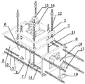
FIG. 1 is a schematic view of the structure of the present invention.
Fig. 2 is a perspective view of the present invention with the fourth and ninth reinforcing plates removed.
Fig. 3 is a perspective view of the present invention after further removing the first jack, the second reinforcing plate and the third reinforcing plate from fig. 2.
In the figure, 1 is a first reinforcing plate, 2 is a second reinforcing plate, 3 is a third reinforcing plate, 4 is a fourth reinforcing plate, 5 is a fifth reinforcing plate, 6 is a sixth reinforcing plate, 7 is a seventh reinforcing plate, 8 is a eighth reinforcing plate, 9 is a ninth reinforcing plate, 10 is a fifth screw, 11 is a first screw, 12 is a second screw, 13 is a third screw, 14 is a fourth screw, 15 is a first sensor, 16 is a first jack, 17 is a second sensor, 18 is a second jack, 19 is a cushion block, and 20 is a concrete sample.
Detailed Description
As shown in fig. 1-3, it is a self-balancing test device for concrete axial tension, which is composed of a vertical tension test mechanism and a horizontal tension test mechanism.
Vertical tensile test mechanism: the reinforcing plate comprises a first reinforcing plate 1, a second reinforcing plate 2, a third reinforcing plate 3 and a fourth reinforcing plate 4 which are parallel to each other and are centered on the same longitudinal axis, wherein the first reinforcing plate 1, the second reinforcing plate 2, the third reinforcing plate 3 and the fourth reinforcing plate 4 are sequentially arranged from bottom to top; the four corners of the first reinforcing plate 1 and the third reinforcing plate 3 are fixedly connected through four first screws 11 which are arranged in parallel respectively; the four corners of the second reinforcing plate 2 and the fourth reinforcing plate 4 are fixedly connected through four second screws 12 which are arranged in parallel respectively; the first screw 11 penetrates through the second reinforcing plate 2 with a gap, and the second screw 12 penetrates through the third reinforcing plate 3 with a gap; a first jack 16 is arranged between the third reinforcing plate 3 and the fourth reinforcing plate 4, the bottom of the first jack 16 is supported in the center of the third reinforcing plate 3, and a first pressure sensor 15 is arranged between the top of the first jack 16 and the center of the fourth reinforcing plate 4; the reinforcing plate is made of a square metal plate.
Horizontal tensile test mechanism: the device comprises a reinforcing plate five 5, a reinforcing plate six 6, a reinforcing plate seven 7, a reinforcing plate eight 8 and a reinforcing plate nine 9 which are parallel to each other and have centers positioned on the same axis; the four corners of the reinforcing plate five 5 and the reinforcing plate eight 8 are fixedly connected through four third screw rods 13 which are arranged in parallel respectively; the four corners of the seventh reinforcing plate 7 and the ninth reinforcing plate 9 are fixedly connected through four fourth screws 14 arranged in parallel respectively; the fourth screw 14 penetrates through the eighth reinforcing plate 8 with a gap, and the four corners of the fifth reinforcing plate 5 and the sixth reinforcing plate 6 are fixedly connected through the four fifth screws 10; a second jack 18 is arranged between the eighth reinforcing plate 8 and the ninth reinforcing plate 9, one end of the second jack 18 is supported at the center of the eighth reinforcing plate 8, and a second pressure sensor 17 is arranged between the other end of the second jack 18 and the center of the ninth reinforcing plate 9.
The reinforcing plate six 6 and the reinforcing plate seven 7 are positioned between the reinforcing plate I1 and the reinforcing plate II 2; a space for placing the concrete test piece 20 is formed by enclosing the first reinforcing plate 1, the second reinforcing plate 2, the sixth reinforcing plate 6 and the seventh reinforcing plate 7; during testing, the upper surface, the lower surface, the left surface and the right surface of the concrete sample 20 are respectively bonded on the second reinforcing plate 2, the first reinforcing plate 1, the sixth reinforcing plate 6 and the seventh reinforcing plate 7 through epoxy resin glue.
The reinforcing plate six 6 and the reinforcing plate seven 7 can be movably placed on the upper surface of the reinforcing plate I1, cushion blocks 19 are welded on the side faces of the jack II 18, and the bottoms of the cushion blocks 19 and the bottom surface of the reinforcing plate I1 are on the same horizontal plane, so that the axis of the jack II 18 coincides with the axes of the reinforcing plate five 5, the reinforcing plate six 6, the reinforcing plate seven 7, the reinforcing plate eight 8 and the reinforcing plate nine 9.
The first jack 16 and the second jack 18 are separated hydraulic jacks; the first sensor 15 and the second sensor 17 are spoke type tension and compression sensors.
When the concrete type sample tensile test is carried out, the following test method is adopted:
1) a concrete specimen 20 having a rectangular horizontal section was prepared.
2) And (3) releasing the pressure and taking out the first jack 16, the second jack 18, the first sensor 15 and the second sensor 17, so that the first reinforcing plate 1 and the second reinforcing plate 2 can move relatively, and meanwhile, the sixth reinforcing plate 6 and the seventh reinforcing plate 7 can move relatively.
3) And placing the concrete sample 20 into a space surrounded by the first reinforcing plate 1, the second reinforcing plate 2, the sixth reinforcing plate 6 and the seventh reinforcing plate 7, so that the concrete sample 20 is in contact with the first reinforcing plate 1, the second reinforcing plate 2, the sixth reinforcing plate 6 and the seventh reinforcing plate 7.
4) And coating epoxy resin glue on the contact surfaces of the concrete sample 20 and the first reinforcing plate 1, the second reinforcing plate 2, the sixth reinforcing plate 6 and the seventh reinforcing plate 7 until the epoxy resin glue is fully cured.
5) Loading a first jack 16, a second jack 18, a first sensor 15 and a second sensor 17, synchronously applying pressure in the vertical direction and the horizontal direction by using the first jack 16 and the second jack 18, forming a vertical tensile force between the first reinforcing plate 1 and the second reinforcing plate 2 by using the pressure from the first jack 16, and forming a horizontal tensile force between the sixth reinforcing plate 6 and the seventh reinforcing plate 7 by using the pressure from the second jack 18 until the concrete sample 20 is subjected to tensile fracture; readings from sensor one 15 and sensor two 17 are continuously recorded during the stretching process.
The beneficial effects are as follows:
(1) the testing device is combined on the basis of the steel plate and the screw, has small structural mass, is convenient to transport and install, and can be directly manufactured in a factory.
(2) The testing device can quickly, effectively and accurately perform a concrete axis tension test, can convert the pressure of the jack into tension, and can ensure that the axis of the concrete sample 20 is tensioned as the jack and the concrete sample 20 are arranged coaxially; eccentric stress can be avoided.
(3) In the vertical direction, the first reinforcing plate 1 and the third reinforcing plate 3 form a whole, the second reinforcing plate 2 and the fourth reinforcing plate 4 form a whole, and the two whole can be self-balanced by the force from the concrete sample 20 and the first jack 16 during test operation, so that the concrete sample 20 is not subjected to the action of an eccentric load in the longitudinal direction; similarly, the same is true in the horizontal direction, except that, in the horizontal direction, the five reinforcing plates 5, the six reinforcing plates 6 and the eight reinforcing plates 8 form a whole, and the six reinforcing plates 6 are arranged, so that the concrete test piece 20 with smaller size can be conveniently installed, and the whole device cannot deflect in the whole installation process before the first jack 16 and the second jack 18 work.
(4) It has realized from vertical and horizontal two orientation tensile test concrete sample 20 simultaneously, and the tensile strength when can be more accurate test concrete member atress simultaneously in two orientations.
The present invention is not limited to the above-mentioned embodiments, and based on the technical solutions disclosed in the present invention, those skilled in the art can make some substitutions and modifications to some technical features without creative efforts according to the disclosed technical contents, and these substitutions and modifications are all within the protection scope of the present invention.
Claims (5)
1. The utility model provides a concrete axle center is drawn self-balancing test device which characterized in that: the device comprises a vertical tensile testing mechanism and a horizontal tensile testing mechanism;
vertical tensile test mechanism: the reinforcing plate I, the reinforcing plate II, the reinforcing plate III and the reinforcing plate IV are mutually parallel and are positioned on the same longitudinal axis in the center, and the reinforcing plate I, the reinforcing plate II, the reinforcing plate III and the reinforcing plate IV are sequentially arranged from bottom to top; four corners of the first reinforcing plate and the third reinforcing plate are fixedly connected through four first screws arranged in parallel respectively; the four corners of the second reinforcing plate and the fourth reinforcing plate are fixedly connected through four second screws arranged in parallel respectively; the first screw rod penetrates through the second reinforcing plate at a gap, and the second screw rod penetrates through the third reinforcing plate at a gap; a first jack is arranged between the third reinforcing plate and the fourth reinforcing plate, the bottom of the first jack is supported at the center of the third reinforcing plate, and a first pressure sensor is arranged between the top of the first jack and the center of the fourth reinforcing plate;
horizontal tensile test mechanism: the device comprises a fifth reinforcing plate, a sixth reinforcing plate, a seventh reinforcing plate, an eighth reinforcing plate and a ninth reinforcing plate which are parallel to each other and the centers of which are positioned on the same axis; the four corners of the fifth reinforcing plate and the eighth reinforcing plate are fixedly connected through four third screws arranged in parallel respectively; the four corners of the seventh reinforcing plate and the ninth reinforcing plate are fixedly connected through four fourth screws arranged in parallel respectively; the fourth screw penetrates through the eighth reinforcing plate with a gap, and the fifth reinforcing plate and the six reinforcing plate are fixedly connected through the four fifth screws; a second jack is arranged between the eighth reinforcing plate and the ninth reinforcing plate, one end of the second jack is supported at the center of the eighth reinforcing plate, and a second pressure sensor is arranged between the other end of the second jack and the center of the ninth reinforcing plate;
the first reinforcing plate and the second reinforcing plate are arranged in parallel; a space for placing a concrete test piece is enclosed by the first reinforcing plate, the second reinforcing plate, the sixth reinforcing plate and the seventh reinforcing plate; during testing, the upper surface, the lower surface, the left surface and the right surface of the concrete sample are respectively bonded on the second reinforcing plate, the first reinforcing plate, the sixth reinforcing plate and the seventh reinforcing plate through epoxy resin glue.
2. The concrete axial tension self-balancing test device of claim 1, wherein: the six reinforcing plates and the seven reinforcing plates are movably placed on the upper surface of the first reinforcing plate, cushion blocks are welded on the side faces of the second jack, and the bottoms of the cushion blocks and the bottom surface of the first reinforcing plate are on the same horizontal plane, so that the axis of the second jack coincides with the axes of the fifth reinforcing plate, the sixth reinforcing plate, the seventh reinforcing plate, the eighth reinforcing plate and the ninth reinforcing plate.
3. The concrete axial tension self-balancing test device according to claim 1 or 2, characterized in that: the first jack and the second jack are separated hydraulic jacks.
4. The concrete axial tension self-balancing test device according to claim 1 or 2, characterized in that: the first sensor and the second sensor are spoke type tension and compression sensors.
5. The test method of the concrete axial tension self-balancing test device according to claim 1 or 2, characterized by comprising the following steps:
1) preparing a concrete test piece with a rectangular horizontal section;
2) releasing the pressure and taking out the first jack, the second jack, the first sensor and the second sensor, so that the first reinforcing plate and the second reinforcing plate can move relatively, and meanwhile, the sixth reinforcing plate and the seventh reinforcing plate can move relatively;
3) placing the concrete sample into a space surrounded by the first reinforcing plate, the second reinforcing plate, the sixth reinforcing plate and the seventh reinforcing plate to make the concrete sample contact with the first reinforcing plate, the second reinforcing plate, the sixth reinforcing plate and the seventh reinforcing plate;
4) coating epoxy resin glue on contact surfaces of the concrete sample and the first reinforcing plate, the second reinforcing plate, the sixth reinforcing plate and the seventh reinforcing plate, and fully curing the epoxy resin glue;
5) loading a first jack, a second jack, a first sensor and a second sensor, synchronously applying pressure in the vertical direction and the horizontal direction by using the first jack and the second jack, forming a vertical tensile force between the first reinforcing plate and the second reinforcing plate by using the pressure from the first jack, and forming a horizontal tensile force between the sixth reinforcing plate and the seventh reinforcing plate by using the pressure from the second jack until the concrete sample is stretched and broken; and continuously recording the readings of the first sensor and the second sensor in the stretching process.
Priority Applications (1)
| Application Number | Priority Date | Filing Date | Title |
|---|---|---|---|
| CN202111269960.4A CN114018714B (en) | 2021-10-29 | 2021-10-29 | A concrete axial tension self-balancing test device and test method |
Applications Claiming Priority (1)
| Application Number | Priority Date | Filing Date | Title |
|---|---|---|---|
| CN202111269960.4A CN114018714B (en) | 2021-10-29 | 2021-10-29 | A concrete axial tension self-balancing test device and test method |
Publications (2)
| Publication Number | Publication Date |
|---|---|
| CN114018714A true CN114018714A (en) | 2022-02-08 |
| CN114018714B CN114018714B (en) | 2025-01-17 |
Family
ID=80058657
Family Applications (1)
| Application Number | Title | Priority Date | Filing Date |
|---|---|---|---|
| CN202111269960.4A Active CN114018714B (en) | 2021-10-29 | 2021-10-29 | A concrete axial tension self-balancing test device and test method |
Country Status (1)
| Country | Link |
|---|---|
| CN (1) | CN114018714B (en) |
Cited By (1)
| Publication number | Priority date | Publication date | Assignee | Title |
|---|---|---|---|---|
| CN115791449A (en) * | 2022-11-30 | 2023-03-14 | 长安大学 | Self-balancing loading device for concrete direct shear test |
Citations (19)
| Publication number | Priority date | Publication date | Assignee | Title |
|---|---|---|---|---|
| JPH0466841A (en) * | 1990-07-06 | 1992-03-03 | Fudo Constr Co Ltd | Testing apparatus of dynamical characteristic of rc-constructed or src-constructed beam member |
| JP2004271289A (en) * | 2003-03-07 | 2004-09-30 | Civil Engineering Research Institute Of Hokkaido | Concrete uniaxial tensile tester |
| JP2006242587A (en) * | 2005-02-28 | 2006-09-14 | Mitsubishi Heavy Ind Ltd | Strength testing machine of structure |
| CN101408489A (en) * | 2008-11-21 | 2009-04-15 | 哈尔滨工业大学 | Concrete plane complicated applied force test device |
| CN103063509A (en) * | 2012-12-29 | 2013-04-24 | 西安建筑科技大学 | Bidirectional self-balance shear loading device for fired shale masonry and test method therefor |
| CN103207121A (en) * | 2013-03-21 | 2013-07-17 | 河海大学 | Constant-axial-force self-balanced loading device for different column section joints |
| CN105259020A (en) * | 2015-11-20 | 2016-01-20 | 天津大学 | Seismic performance test loading device for shear wall under combined action of pulling, bending and shearing |
| CN206161422U (en) * | 2016-11-20 | 2017-05-10 | 山东科技大学 | Hydraulic pressure counter -force loading device for be used for test piece loading experiments |
| CN107167378A (en) * | 2017-05-16 | 2017-09-15 | 华北理工大学 | Axial tension experimental rig and its test method |
| CN107807039A (en) * | 2017-11-28 | 2018-03-16 | 湖南大学 | Lever long duration load tests loading frame |
| CN107884292A (en) * | 2017-10-18 | 2018-04-06 | 潍坊科技学院 | A kind of complementary energy of curvature-prevention support component and remaining life Forecasting Methodology and device |
| CN207964442U (en) * | 2017-11-28 | 2018-10-12 | 湖南大学 | Lever long duration load tests loading frame |
| CN109632470A (en) * | 2018-12-11 | 2019-04-16 | 上海市基础工程集团有限公司 | For section of jurisdiction plate connector mechanical property test device |
| CN110146384A (en) * | 2019-05-20 | 2019-08-20 | 浙江大学 | A test device and test method for testing the direct shear performance of concrete bonding interface under axial pressure |
| CN110595901A (en) * | 2019-09-29 | 2019-12-20 | 扬州大学 | A new truss joint self-balancing test device and its test method |
| CN211690464U (en) * | 2019-11-20 | 2020-10-16 | 湖北鄂东桩基工程有限公司 | Uplift resistance detection test device for small and medium-diameter piles |
| CN211955007U (en) * | 2020-04-17 | 2020-11-17 | 聊城大学 | Novel concrete axial tension test device |
| CN213358709U (en) * | 2020-07-29 | 2021-06-04 | 苏州江南意造建筑设计有限公司 | Uplift pile detection device |
| CN214173967U (en) * | 2020-12-09 | 2021-09-10 | 湖南工业大学 | Self-balancing constant loading bending creep test device |
-
2021
- 2021-10-29 CN CN202111269960.4A patent/CN114018714B/en active Active
Patent Citations (19)
| Publication number | Priority date | Publication date | Assignee | Title |
|---|---|---|---|---|
| JPH0466841A (en) * | 1990-07-06 | 1992-03-03 | Fudo Constr Co Ltd | Testing apparatus of dynamical characteristic of rc-constructed or src-constructed beam member |
| JP2004271289A (en) * | 2003-03-07 | 2004-09-30 | Civil Engineering Research Institute Of Hokkaido | Concrete uniaxial tensile tester |
| JP2006242587A (en) * | 2005-02-28 | 2006-09-14 | Mitsubishi Heavy Ind Ltd | Strength testing machine of structure |
| CN101408489A (en) * | 2008-11-21 | 2009-04-15 | 哈尔滨工业大学 | Concrete plane complicated applied force test device |
| CN103063509A (en) * | 2012-12-29 | 2013-04-24 | 西安建筑科技大学 | Bidirectional self-balance shear loading device for fired shale masonry and test method therefor |
| CN103207121A (en) * | 2013-03-21 | 2013-07-17 | 河海大学 | Constant-axial-force self-balanced loading device for different column section joints |
| CN105259020A (en) * | 2015-11-20 | 2016-01-20 | 天津大学 | Seismic performance test loading device for shear wall under combined action of pulling, bending and shearing |
| CN206161422U (en) * | 2016-11-20 | 2017-05-10 | 山东科技大学 | Hydraulic pressure counter -force loading device for be used for test piece loading experiments |
| CN107167378A (en) * | 2017-05-16 | 2017-09-15 | 华北理工大学 | Axial tension experimental rig and its test method |
| CN107884292A (en) * | 2017-10-18 | 2018-04-06 | 潍坊科技学院 | A kind of complementary energy of curvature-prevention support component and remaining life Forecasting Methodology and device |
| CN107807039A (en) * | 2017-11-28 | 2018-03-16 | 湖南大学 | Lever long duration load tests loading frame |
| CN207964442U (en) * | 2017-11-28 | 2018-10-12 | 湖南大学 | Lever long duration load tests loading frame |
| CN109632470A (en) * | 2018-12-11 | 2019-04-16 | 上海市基础工程集团有限公司 | For section of jurisdiction plate connector mechanical property test device |
| CN110146384A (en) * | 2019-05-20 | 2019-08-20 | 浙江大学 | A test device and test method for testing the direct shear performance of concrete bonding interface under axial pressure |
| CN110595901A (en) * | 2019-09-29 | 2019-12-20 | 扬州大学 | A new truss joint self-balancing test device and its test method |
| CN211690464U (en) * | 2019-11-20 | 2020-10-16 | 湖北鄂东桩基工程有限公司 | Uplift resistance detection test device for small and medium-diameter piles |
| CN211955007U (en) * | 2020-04-17 | 2020-11-17 | 聊城大学 | Novel concrete axial tension test device |
| CN213358709U (en) * | 2020-07-29 | 2021-06-04 | 苏州江南意造建筑设计有限公司 | Uplift pile detection device |
| CN214173967U (en) * | 2020-12-09 | 2021-09-10 | 湖南工业大学 | Self-balancing constant loading bending creep test device |
Cited By (1)
| Publication number | Priority date | Publication date | Assignee | Title |
|---|---|---|---|---|
| CN115791449A (en) * | 2022-11-30 | 2023-03-14 | 长安大学 | Self-balancing loading device for concrete direct shear test |
Also Published As
| Publication number | Publication date |
|---|---|
| CN114018714B (en) | 2025-01-17 |
Similar Documents
| Publication | Publication Date | Title |
|---|---|---|
| CN101275892B (en) | Concrete Multi-Factor Durability Experimental Device Under the Coupling Action of Bending-tensile Stress and Environment | |
| AU2020101793A4 (en) | Test device for testing bond strength of reinforced concrete | |
| CN1318834C (en) | Direct shear test machine for rock | |
| CN102564870B (en) | Crack-propagation test method and device | |
| CN101408489B (en) | Concrete plane complicated applied force test device | |
| CN106124313B (en) | Test device for comprehensive deformation properties of concrete and similar materials under compression | |
| CN201788123U (en) | A bonded anchor pull-out test device | |
| CN211602720U (en) | A new type of rock and soil bearing capacity testing device | |
| CN102519871A (en) | Method and device for measuring bonding strength between reinforcing steel and concrete under action of pre-stress | |
| CN1392400A (en) | Non-destructive testing method and device for mechanical property of brittle material | |
| CN104931352A (en) | Method of testing Poisson's ratio of concrete | |
| CN206208671U (en) | A kind of rock staight scissors and Point Load Tests device | |
| CN114018714B (en) | A concrete axial tension self-balancing test device and test method | |
| CN108593433A (en) | A test device and test method for direct stretching of rocks in water environment | |
| CN111947564A (en) | Rock sample deformation measuring device, equipment and method | |
| CN205175824U (en) | Apply test device that lasting axle drew damage load to a plurality of concrete samples | |
| CN104596856A (en) | Uniaxial tension compression system | |
| CN201285357Y (en) | Concrete plane complicated applied force test device | |
| CN210376012U (en) | A loading system for stiffened rib-reinforced rectangular concrete-filled steel tubular columns | |
| CN219532721U (en) | Clamping device for analyzing strain parameters of concrete | |
| CN219532801U (en) | Bias calibration device of pressure testing machine | |
| CN203443724U (en) | Thin-wall concrete structure multi-strand flat anchor pre-stress measuring system | |
| CN220854409U (en) | Clamping device for compression test after impact | |
| CN115508187A (en) | Load-keeping device | |
| CN204479411U (en) | Single shaft tensile and compression testing machine |
Legal Events
| Date | Code | Title | Description |
|---|---|---|---|
| PB01 | Publication | ||
| PB01 | Publication | ||
| SE01 | Entry into force of request for substantive examination | ||
| SE01 | Entry into force of request for substantive examination | ||
| GR01 | Patent grant | ||
| GR01 | Patent grant |