CN114011772B - A device for particle copper shaping - Google Patents
A device for particle copper shaping Download PDFInfo
- Publication number
- CN114011772B CN114011772B CN202210000532.XA CN202210000532A CN114011772B CN 114011772 B CN114011772 B CN 114011772B CN 202210000532 A CN202210000532 A CN 202210000532A CN 114011772 B CN114011772 B CN 114011772B
- Authority
- CN
- China
- Prior art keywords
- copper
- cleaning
- copper plate
- sleeve
- hole
- Prior art date
- Legal status (The legal status is an assumption and is not a legal conclusion. Google has not performed a legal analysis and makes no representation as to the accuracy of the status listed.)
- Expired - Fee Related
Links
Images



Classifications
-
- B—PERFORMING OPERATIONS; TRANSPORTING
- B08—CLEANING
- B08B—CLEANING IN GENERAL; PREVENTION OF FOULING IN GENERAL
- B08B1/00—Cleaning by methods involving the use of tools
- B08B1/30—Cleaning by methods involving the use of tools by movement of cleaning members over a surface
- B08B1/32—Cleaning by methods involving the use of tools by movement of cleaning members over a surface using rotary cleaning members
-
- B—PERFORMING OPERATIONS; TRANSPORTING
- B08—CLEANING
- B08B—CLEANING IN GENERAL; PREVENTION OF FOULING IN GENERAL
- B08B13/00—Accessories or details of general applicability for machines or apparatus for cleaning
Landscapes
- Cleaning And De-Greasing Of Metallic Materials By Chemical Methods (AREA)
Abstract
本发明公开了一种用于粒子铜整形的设备,包括用于回转清除铜板表面颗粒的清除件,还包括供气装置,所述供气装置为清除件供气并在清除件和铜板之间形成气垫,支撑所述清除件在铜板的表面浮动。本发明的用于粒子铜整形的设备具有有效清除粒子铜、又避免伤害产品表面、修复效率高且降低人工成本等优点。

The invention discloses a device for particle copper shaping, comprising a cleaning member for rotating and removing particles on the surface of a copper plate, and an air supply device, the air supply device supplies air for the cleaning member and is located between the cleaning member and the copper plate An air cushion is formed to support the scavenger to float on the surface of the copper plate. The device for particle copper shaping of the present invention has the advantages of effectively removing the particle copper, avoiding damage to the product surface, high repairing efficiency, and reducing labor costs.
Description
技术领域technical field
本发明涉及有色冶金技术领域,尤其涉及一种用于粒子铜整形的设备。The invention relates to the technical field of non-ferrous metallurgy, in particular to a device for shaping copper particles.
背景技术Background technique
阴极铜,也称作电解铜,是生产活动中非常重要的有色金属,被广泛地应用于各行各业,在我国有色金属材料的消费中仅次于铝。但工业生产阴极铜的过程中,由于电解液中杂质的影响,会在阴极板表面上形成颗粒状堆积,即粒子铜。粒子铜的出现影响产品的质量和品级,粒子铜重新回炉的百分率是各精铜生产厂家重要的经济效益考核指标。这些带有瑕疵的产品直接回炉、电解不仅会直接降低企业的经济效益,还会增加能源消耗以及单位质量精铜生产的环境污染。Cathode copper, also known as electrolytic copper, is a very important non-ferrous metal in production activities and is widely used in all walks of life. It is second only to aluminum in the consumption of non-ferrous metal materials in my country. However, in the process of industrial production of cathode copper, due to the influence of impurities in the electrolyte, a granular accumulation, that is, particle copper, will be formed on the surface of the cathode plate. The appearance of particle copper affects the quality and grade of the product. The percentage of particle copper that is returned to the furnace is an important economic benefit assessment indicator for each refined copper manufacturer. The direct return of these defective products to the furnace and electrolysis will not only directly reduce the economic benefits of the enterprise, but also increase energy consumption and environmental pollution per unit mass of refined copper production.
因此各精铜生产企业为了减少粒子铜的回炉率,并提高阴极铜的质量等级,会采用人工手持冲击器对可修复的粒子铜进行清除处理。但目前这种修复方式需要人工将铺设在地面上的粒子铜进行冲击修复,修复效率低,占地面积大,且人工成本高,工作环境恶劣。Therefore, in order to reduce the return rate of particle copper and improve the quality level of cathode copper, each refined copper production enterprise will use a manual hand-held impactor to remove the repairable particle copper. However, at present, this repair method requires manual impact repair of the particle copper laid on the ground. The repair efficiency is low, the floor area is large, the labor cost is high, and the working environment is harsh.
发明内容SUMMARY OF THE INVENTION
本发明要解决的技术问题是克服现有技术的不足,提供一种有效清除粒子铜、又避免伤害产品表面、修复效率高且降低人工成本的用于粒子铜整形的设备。The technical problem to be solved by the present invention is to overcome the deficiencies of the prior art, and to provide a device for particle copper shaping that effectively removes the particle copper, avoids damage to the product surface, has high repair efficiency and reduces labor costs.
为解决上述技术问题,本发明提出的技术方案为:In order to solve the above-mentioned technical problems, the technical scheme proposed by the present invention is:
一种用于粒子铜整形的设备,包括用于回转清除铜板表面颗粒的清除件,还包括供气装置,所述供气装置为清除件供气并在清除件和铜板之间形成气垫,支撑所述清除件在铜板的表面浮动。A device for particle copper shaping, comprising a scavenger for rotating and removing particles on the surface of a copper plate, and an air supply device, the air supply device supplies air to the scavenger and forms an air cushion between the scavenger and the copper plate, supporting the The removal piece floats on the surface of the copper plate.
作为上述技术方案的进一步改进:As a further improvement of the above technical solution:
所述清除件包括连接盘和多个冲击块,所述冲击块连接在连接盘朝向铜板一侧的表面上。The clearing piece includes a connecting plate and a plurality of impact blocks, and the impact blocks are connected on the surface of the connecting plate facing the copper plate.
所述冲击块呈条形,各冲击块绕连接盘的回转中心均匀排布,且冲击块斜置,与连接盘的径向呈夹角。The impact blocks are strip-shaped, and the impact blocks are evenly arranged around the rotation center of the connecting plate, and the impact blocks are obliquely arranged to form an included angle with the radial direction of the connecting plate.
所述连接盘的另一侧表面设有和供气装置接通的第一通孔,所述冲击块上设有气孔,第一通孔和各冲击块的气孔贯通。The other side surface of the connecting plate is provided with a first through hole which is connected with the air supply device, the impact block is provided with an air hole, and the first through hole and the air hole of each impact block pass through.
设备还包括回转驱动组件,所述回转驱动组件驱动清除件回转,且其驱动端和清除件沿回转轴线方向活动连接。The equipment further includes a rotary drive assembly, the rotary drive assembly drives the clearing member to rotate, and the driving end thereof and the clearing member are movably connected along the direction of the rotary axis.
所述回转驱动组件的驱动端上设有内花键,清除件连接驱动端的位置上设有外花键,内花键和外花键沿回转轴线方向套接配合。The driving end of the rotary drive assembly is provided with an inner spline, and the position where the cleaning element is connected to the driving end is provided with an outer spline, and the inner spline and the outer spline are sleeved and matched along the direction of the rotation axis.
所述回转驱动组件包括驱动件、套筒和传动轴,所述传动轴同轴套接连接在套筒内,一端伸出套筒作为连接清除件的驱动端,另一端伸出套筒连接驱动件的输出轴。The rotary drive assembly includes a drive member, a sleeve and a transmission shaft. The transmission shaft is coaxially sleeved and connected in the sleeve. One end extends out of the sleeve as a drive end for connecting the clearing member, and the other end extends out of the sleeve to connect to the drive. the output shaft of the piece.
所述传动轴为端部和清除件表面贯通的空心轴,且传动轴位于套筒内的轴段上设有与空心部分连通的第二通孔;所述套筒上设有和第二通孔位置对应的第三通孔,套筒和传动轴之间在第二通孔的两侧各设有至少一个密封间隙的密封圈;供气装置安装在套筒外,并接通第三通孔。The transmission shaft is a hollow shaft whose end part and the surface of the cleaning member pass through, and the shaft section of the transmission shaft located in the sleeve is provided with a second through hole that communicates with the hollow part; The third through hole corresponding to the position of the hole is provided with at least one sealing ring for sealing the gap between the sleeve and the transmission shaft on both sides of the second through hole; the air supply device is installed outside the sleeve and connected to the third through hole. hole.
设备还包括平面移位机构和用于托持铜板的平面安装台,所述清除件沿垂直于铜板的方向连接在平面移位机构上,并由平面移位机构驱动在铜板平放的平面内移位。The equipment also includes a plane shifting mechanism and a plane mounting platform for holding the copper plate, the clearing member is connected to the plane shifting mechanism along the direction perpendicular to the copper plate, and is driven by the plane shifting mechanism in the plane where the copper plate is laid flat shift.
所述平面移位机构包括第一导轨、移动座、第二导轨和滑台,所述第一导轨布置在与铜板平行的平面上,移动座滑设在第一导轨上,第二导轨沿与第一导轨垂直且与铜板平行的方向布置在移动座上,滑台滑设在第二导轨上,且连接有清除件。The plane displacement mechanism includes a first guide rail, a moving seat, a second guide rail and a sliding table, the first guide rail is arranged on a plane parallel to the copper plate, the moving seat is slidably arranged on the first guide rail, and the second guide rail is arranged along the The first guide rail is vertical and parallel to the copper plate and is arranged on the moving seat, the sliding table is slidably arranged on the second guide rail, and is connected with a cleaning piece.
与现有技术相比,本发明的优点在于:Compared with the prior art, the advantages of the present invention are:
本发明的用于粒子铜整形的设备,包括用于回转清除铜板表面颗粒的清除件,清除件自动化执行清除操作,不需要人工手持冲击器或铲进行清理,因此降低人工成本,不会影响工作人员的健康,且清除效率更高。由于粒子铜板面高低起伏程度较大,直接采用同一清除高度的设备会导致设备要么接触不到较小的颗粒,要么将颗粒夹持在设备与铜板之间,造成铜板表面的二次伤害。因此本设备还包括供气装置,供气装置为清除件供气并在清除件和铜板之间形成气垫,气垫支撑清除件,使清除件在清除过程中能在铜板的表面浮动,这种浮动清除方式能够自动根据间隙的变化或供气量的变化调整清除件和铜板之间的间隙,实现距离的自适应,消除了对刀困难,精确而平整地修复有粒子铜的铜板;同时由于存在气垫,清除件和铜板之间并非一直保持接触,因此不会对铜板形成切割加工,冲击脱离的颗粒不会被清除件压住后划伤铜板表面,避免二次伤害,并且供气装置提供的气流不仅能起到吹动颗粒、使颗粒尽快脱离工作范围的作用,还能为执行冲击清除的清除件提供风冷,保证清除件工作的稳定性。The device for particle copper shaping of the present invention includes a cleaning member for rotating and removing particles on the surface of the copper plate, the cleaning member automatically performs the cleaning operation, and does not require manual cleaning with an impactor or a shovel, so labor costs are reduced and work is not affected. The health of the personnel, and the removal efficiency is higher. Since the surface of the particle copper plate fluctuates greatly, directly using the equipment with the same removal height will cause the equipment to either not touch the smaller particles, or the particles will be clamped between the equipment and the copper plate, causing secondary damage to the surface of the copper plate. Therefore, the equipment also includes an air supply device. The air supply device supplies air to the cleaning element and forms an air cushion between the cleaning element and the copper plate. The air cushion supports the cleaning element so that the cleaning element can float on the surface of the copper plate during the cleaning process. This floating The cleaning method can automatically adjust the gap between the cleaning piece and the copper plate according to the change of the gap or the change of the air supply, realize the self-adaptation of the distance, eliminate the difficulty of tool setting, and repair the copper plate with particle copper accurately and flatly; at the same time, due to the existence of The air cushion, the cleaning piece and the copper plate are not always in contact, so the copper plate will not be cut, and the particles that are impacted and separated will not be pressed by the cleaning piece and scratch the surface of the copper plate to avoid secondary damage. The airflow can not only blow the particles and make the particles leave the working range as soon as possible, but also provide air cooling for the cleaning parts that perform impact removal, so as to ensure the stability of the cleaning parts.
附图说明Description of drawings
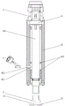
图1是本发明的用于粒子铜整形的设备的结构示意图;Fig. 1 is the structural representation of the equipment for particle copper shaping of the present invention;
图2是本发明的用于粒子铜整形的设备中清除件和回转驱动组件的连接示意图;Fig. 2 is the connection schematic diagram of the cleaning member and the rotary drive assembly in the equipment for particle copper shaping of the present invention;
图3是本发明的用于粒子铜整形的设备中清除件的底面结构示意图;Fig. 3 is the bottom surface structure schematic diagram of the cleaning member in the equipment for particle copper shaping of the present invention;
图4是本发明的用于粒子铜整形的设备中清除件的剖面结构示意图;Fig. 4 is the cross-sectional structure schematic diagram of the cleaning member in the equipment for particle copper shaping of the present invention;
图5是本发明的用于粒子铜整形的设备中清除件的外花键结构示意图。FIG. 5 is a schematic diagram of the external spline structure of the cleaning element in the device for particle copper shaping according to the present invention.
图例说明:1、铜板;2、清除件;21、连接盘;211、第一通孔;22、冲击块;221、气孔;3、供气装置;4、回转驱动组件;41、驱动件;42、套筒;421、第三通孔;422、密封圈;43、传动轴;431、第二通孔;5、平面移位机构;51、第一导轨;52、移动座;53、第二导轨;54、滑台;6、平面安装台。Legend description: 1. Copper plate; 2. Clearing piece; 21. Connecting plate; 211. First through hole; 22. Impact block; 221. Air hole; 3. Air supply device; 4. Rotary drive assembly; 42, sleeve; 421, third through hole; 422, sealing ring; 43, transmission shaft; 431, second through hole; 5, plane displacement mechanism; 51, first guide rail; 52, movable seat; 53, first Two guide rails; 54, sliding table; 6, plane installation table.
具体实施方式Detailed ways
为了便于理解本发明,下文将结合说明书附图和较佳的实施例对本发明做更全面、细致地描述,但本发明的保护范围并不限于以下具体实施例。In order to facilitate the understanding of the present invention, the present invention will be described more comprehensively and in detail below with reference to the accompanying drawings and preferred embodiments of the specification, but the protection scope of the present invention is not limited to the following specific embodiments.
实施例:Example:
如图1和图2所示,本实施例的用于粒子铜整形的设备,包括用于回转清除铜板1表面颗粒的清除件2,清除件2自动化执行清除操作,不需要人工手持冲击器或铲进行清理,因此降低人工成本,不会影响工作人员的健康,且解放了生产力,提高工厂的生产效率和经济效益。As shown in FIG. 1 and FIG. 2 , the device for particle copper shaping in this embodiment includes a
由于粒子铜板面高低起伏程度较大,直接采用同一清除高度的设备会导致设备要么接触不到较小的颗粒,要么将颗粒夹持在设备与铜板1之间,造成铜板1表面的二次伤害。因此本设备还包括供气装置3,供气装置3为清除件2供气并在清除件2和铜板1之间形成气垫,支撑清除件2在铜板1的表面浮动,这种浮动清除方式能够自动调整清除件2和铜板1之间的间隙,实现距离的自适应,精确而平整地修复有粒子铜的铜板1;同时由于存在气垫,清除件2和铜板1之间并非一直保持接触,因此冲击脱离的颗粒不会被清除件2压住后划伤铜板1表面,避免二次伤害,并且供气装置3提供的气流不仅能起到吹动颗粒、使颗粒尽快脱离工作范围的作用,还能为执行冲击清除的清除件2提供风冷,保证清除件2工作的稳定性。Since the surface of the particle copper plate fluctuates greatly, directly using the equipment with the same cleaning height will cause the equipment to either not be able to contact the smaller particles, or the particles will be clamped between the equipment and the
本实施例中,如图3所示,清除件2包括连接盘21和多个冲击块22,冲击块22通过螺栓等紧固件连接在连接盘21朝向铜板1一侧的表面上,使清除件2的底面不是一个平整的平面,而是由凸出的冲击块22形成了高低不平的表面,因此清除件2在回转的过程中,不仅通过冲击块22底面与颗粒之间的摩擦带动颗粒脱离,还能通过冲击块22侧面直接刮动颗粒使其脱离,进一步提高了清除的效率和效果。In this embodiment, as shown in FIG. 3 , the cleaning
本实施例中,冲击块22呈条形,各冲击块22绕连接盘21的回转中心均匀排布,且冲击块22斜置,与连接盘21的径向呈夹角。如图4所示,连接盘21的另一侧表面设有和供气装置3接通的第一通孔211,冲击块22上设有气孔221,第一通孔211和各冲击块22的气孔221贯通,从而使供气装置3提供的气体沿第一通孔211和气孔221冲至清除件2的表面。斜置的冲击块22还能为气体提供导向作用,使受冲击脱离的颗粒随气体更快吹出工作范围。In this embodiment, the impact blocks 22 are strip-shaped, and the impact blocks 22 are evenly arranged around the rotation center of the connecting
本实施例中,设备还包括回转驱动组件4,回转驱动组件4驱动清除件2回转,使其能够清除铜板1表面的颗粒。其驱动端和清除件2沿回转轴线方向活动连接,不限制清除件2的浮动,避免干涉气垫的自适应调整作用。In this embodiment, the apparatus further includes a
本实施例中,回转驱动组件4的驱动端上设有内花键,清除件2连接驱动端的位置上设有外花键,如图5所示,二者通过内花键和外花键套接配合,既能实现回转力的传动,又不会影响轴向的浮动。In this embodiment, the driving end of the
本实施例中,如图2所示,回转驱动组件4包括驱动件41、套筒42和传动轴43,传动轴43同轴套接连接在套筒42内,一端伸出套筒42作为连接清除件2的驱动端,另一端伸出套筒42连接驱动件41的输出轴,套筒42既保护了传动轴43,又为驱动件41和其他设备提供了连接安装位置。传动轴43和套筒42之间可以通过轴承连接,保持同轴位置关系,套筒42的端部还可以设置带有通孔的端盖,既不影响传动轴43伸出,又能保证内部的封闭性。In this embodiment, as shown in FIG. 2 , the
本实施例中,传动轴43为端部和清除件2表面贯通的空心轴,且传动轴43位于套筒42内的轴段上设有与空心部分连通的第二通孔431;套筒42上设有和第二通孔431位置对应的第三通孔421,套筒42和传动轴43之间在第二通孔431的两侧各设有至少一个密封间隙的密封圈422;供气装置3安装在套筒42外,并接通第三通孔421。供气装置3在提供气体时,气流先经过第三通孔421进入到套筒42和传动轴43之间的间隙中,被密封圈422限制在第二通孔431所在的圆周位置处,然后通过第二通孔431进入到传动轴43内部中空区域,再由传动轴43导向到清除件2。本设备的结构中,供气装置3直接连接在套筒42上,避免回转,其供气通路不需要管路,因此不会因回转导致缠绕等问题。第三通孔421处可以设置节流阀、调速阀等来控制进气量。In this embodiment, the
本实施例中,设备还包括平面移位机构5和用于托持铜板1的平面安装台6,平面安装台6上可以设置固定铜板1的夹具。清除件2沿垂直于铜板1的方向,通过回转驱动组件4间接连接在平面移位机构5上,并由平面移位机构5驱动在铜板1平放的平面内移位,确保能够对铜板1上任意位置的粒子铜进行清除工作。In this embodiment, the device further includes a
实际使用过程中,平面移位机构5可以采用轨道式机械结构或者直接采用机械手实现,由机械手作平面运动,铜板1固定在平面上,两种方案均属于本设备的保护方案,本实施例中,如图1所示,平面移位机构5采用了轨道式机械结构,包括第一导轨51、移动座52、第二导轨53和滑台54,第一导轨51布置在与铜板1平行的平面上,移动座52滑设在第一导轨51上,第二导轨53沿与第一导轨51垂直且与铜板1平行的方向布置在移动座52上,滑台54滑设在第二导轨53上,第一导轨51和第二导轨53形成了覆盖铜板1所在平面的滑动轨道,且二者设置位置的不同,又使二者之间不会相互干涉。滑台54通过回转驱动组件4连接有清除件2,进一步的,回转驱动组件4中的套筒42外表面与滑台54连接。In actual use, the
以上所述仅是本发明的优选实施方式,本发明的保护范围并不仅局限于上述实施例。对于本领域的技术人员来说,在不脱离本发明的技术构思前提下所得到的改进和变换也应视为本发明的保护范围。The above are only preferred embodiments of the present invention, and the protection scope of the present invention is not limited to the above embodiments. For those skilled in the art, improvements and transformations obtained without departing from the technical concept of the present invention should also be regarded as the protection scope of the present invention.
Claims (5)
Priority Applications (1)
| Application Number | Priority Date | Filing Date | Title |
|---|---|---|---|
| CN202210000532.XA CN114011772B (en) | 2022-01-04 | 2022-01-04 | A device for particle copper shaping |
Applications Claiming Priority (1)
| Application Number | Priority Date | Filing Date | Title |
|---|---|---|---|
| CN202210000532.XA CN114011772B (en) | 2022-01-04 | 2022-01-04 | A device for particle copper shaping |
Publications (2)
| Publication Number | Publication Date |
|---|---|
| CN114011772A CN114011772A (en) | 2022-02-08 |
| CN114011772B true CN114011772B (en) | 2022-04-15 |
Family
ID=80069530
Family Applications (1)
| Application Number | Title | Priority Date | Filing Date |
|---|---|---|---|
| CN202210000532.XA Expired - Fee Related CN114011772B (en) | 2022-01-04 | 2022-01-04 | A device for particle copper shaping |
Country Status (1)
| Country | Link |
|---|---|
| CN (1) | CN114011772B (en) |
Citations (6)
| Publication number | Priority date | Publication date | Assignee | Title |
|---|---|---|---|---|
| EP0549377A2 (en) * | 1991-12-27 | 1993-06-30 | Shin-Etsu Handotai Company Limited | A scrubber apparatus for cleaning a thin disk work |
| US6398622B1 (en) * | 2000-12-12 | 2002-06-04 | Asea Brown Boveri Ltd. | Polishing mechanism for vehicle bumper |
| CN201664866U (en) * | 2009-10-19 | 2010-12-08 | 泉州正鑫机械有限公司 | Abrasive finishing machine |
| CN102151990A (en) * | 2011-04-01 | 2011-08-17 | 江苏大学 | Rotary laser head auxiliary gas transmission device for laser processing machine tool |
| CN205465556U (en) * | 2016-01-13 | 2016-08-17 | 北京海普瑞森科技发展有限公司 | Ball grinding machine |
| CN211103267U (en) * | 2019-12-05 | 2020-07-28 | 开平市力泰五金制品有限公司 | Reciprocating telescopic polishing machine |
Family Cites Families (1)
| Publication number | Priority date | Publication date | Assignee | Title |
|---|---|---|---|---|
| FR2882673B1 (en) * | 2005-03-07 | 2008-10-31 | Christian Diat | PNEUMATIC TOOL WITH SANDING EFFECT |
-
2022
- 2022-01-04 CN CN202210000532.XA patent/CN114011772B/en not_active Expired - Fee Related
Patent Citations (6)
| Publication number | Priority date | Publication date | Assignee | Title |
|---|---|---|---|---|
| EP0549377A2 (en) * | 1991-12-27 | 1993-06-30 | Shin-Etsu Handotai Company Limited | A scrubber apparatus for cleaning a thin disk work |
| US6398622B1 (en) * | 2000-12-12 | 2002-06-04 | Asea Brown Boveri Ltd. | Polishing mechanism for vehicle bumper |
| CN201664866U (en) * | 2009-10-19 | 2010-12-08 | 泉州正鑫机械有限公司 | Abrasive finishing machine |
| CN102151990A (en) * | 2011-04-01 | 2011-08-17 | 江苏大学 | Rotary laser head auxiliary gas transmission device for laser processing machine tool |
| CN205465556U (en) * | 2016-01-13 | 2016-08-17 | 北京海普瑞森科技发展有限公司 | Ball grinding machine |
| CN211103267U (en) * | 2019-12-05 | 2020-07-28 | 开平市力泰五金制品有限公司 | Reciprocating telescopic polishing machine |
Also Published As
| Publication number | Publication date |
|---|---|
| CN114011772A (en) | 2022-02-08 |
Similar Documents
| Publication | Publication Date | Title |
|---|---|---|
| CN106346351B (en) | A kind of metallic mirror surface polishing machine | |
| CN201619009U (en) | Vertical paralleled surface grinding machine | |
| CN107234266A (en) | A kind of Full-automatic drilling production line of communication base station internal stent | |
| CN106735577B (en) | A kind of crankshaft deburring machine | |
| CN110745553A (en) | Glass Pretreatment Line | |
| CN108311729A (en) | A kind of friction plate steel back Full-automatic drilling equipment | |
| CN206373469U (en) | A kind of continuous submerged arc overlaying welding device of large-scale milling roller surface | |
| CN205950392U (en) | Chip removal device to drilling and milling machine T type groove workstation | |
| CN105364692B (en) | The automatic polishing device of globe joint | |
| CN116394123B (en) | Centering grinding and polishing integrated processing equipment | |
| CN103433830A (en) | Polishing and rust removing machine for iron roof of passenger vehicle | |
| CN209319396U (en) | A kind of cleaning device of machine tool guideway | |
| CN107677561A (en) | A kind of rail milling experimental rig | |
| CN206200317U (en) | A kind of automatic welding blows cuts lathe | |
| CN102837932B (en) | Continuous flat-pushing type discharge device and discharge method thereof | |
| CN120083109A (en) | Road maintenance equipment for traffic engineering | |
| CN211681338U (en) | Floating grinding head for processing holes in glass plate | |
| CN114011772A (en) | A device for particle copper shaping | |
| CN209256617U (en) | Adjustable steel wire rust removing machine | |
| CN109423591A (en) | A kind of online air knife clears up system automatically | |
| CN211103090U (en) | Double-end-face vertical grinding machine | |
| CN202240923U (en) | Transverse walking device for automatic pipeline joint coating sealing deruster | |
| CN206568352U (en) | A kind of multitool cutting machine | |
| CN207013837U (en) | A kind of numerical control processing apparatus | |
| CN201731736U (en) | Product dewatering machine |
Legal Events
| Date | Code | Title | Description |
|---|---|---|---|
| PB01 | Publication | ||
| PB01 | Publication | ||
| SE01 | Entry into force of request for substantive examination | ||
| SE01 | Entry into force of request for substantive examination | ||
| GR01 | Patent grant | ||
| GR01 | Patent grant | ||
| CF01 | Termination of patent right due to non-payment of annual fee |
Granted publication date: 20220415 |
|
| CF01 | Termination of patent right due to non-payment of annual fee |