Disclosure of Invention
The invention provides an air conditioner which has the advantages of simple structure and small floor area.
The air conditioner comprises a shell, a first heat exchanger, a first fan assembly, a second heat exchanger, a second fan assembly and a compressor, wherein a first air duct and a second air duct are defined in the shell, the first air duct and the second air duct are distributed in the horizontal direction, a first air inlet and a first air outlet which are communicated with the first air duct are formed in the shell, and a second air inlet and a second air outlet which are communicated with the second air duct are also formed in the shell; the first heat exchanger is arranged in the first air duct, and two ends of the first heat exchanger are connected with the shell through fasteners; the first fan assembly is arranged in the first air duct to drive airflow to flow from the first air inlet to the first air outlet; the second heat exchanger is arranged in the second air duct, one of the first heat exchanger and the second heat exchanger is a condenser, the other of the first heat exchanger and the second heat exchanger is an evaporator, and two ends of the second heat exchanger are connected with the shell through fasteners; the second fan assembly is arranged in the second air duct to drive airflow to flow from the second air inlet to the second air outlet; the compressor is arranged in one of the first air duct and the second air duct, and the compressor, the first heat exchanger and the second heat exchanger form a heat exchange flow path.
According to the air conditioner provided by the embodiment of the invention, the first air duct and the second air duct are arranged in the shell in the horizontal direction, and the first heat exchanger and the first fan assembly are arranged in the first air duct, wherein the first heat exchanger is connected with the shell through the threaded fastener, so that hot air entering the first air duct from the first air inlet can be converted into cold air and blown out from the first air outlet; set up second heat exchanger and second fan subassembly in the second wind channel, wherein, the second heat exchanger passes through threaded fastener with the casing and is connected, from this, can convert the air current that the second air intake got into the wind channel into the hot gas flow and blow off from the second air outlet to can guarantee going on smoothly of refrigeration cycle.
According to the air conditioner, the first air duct and the second air duct are arranged on the shell, and refrigeration in the first air duct and heating in the second air duct can be conducted without mutual interference, so that the air conditioner is simple in structure and convenient to install, holes do not need to be drilled in a wall, and the integrity and the attractiveness of home decoration can be kept. And the horizontal arrangement of the first air duct and the second air duct enables the structure of the air conditioner to be small, and the indoor occupied area can be saved when the air conditioner is placed. In addition, the first heat exchanger and the second heat exchanger are connected to the housing by threaded fasteners, which can improve the replaceability and maintainability of the first heat exchanger and the second heat exchanger.
In some embodiments, a bottom wall of the casing is provided with a first support rib for supporting the first heat exchanger and a second support rib for supporting the second heat exchanger, the first support rib extends along an extending direction of the first heat exchanger, and the second support rib extends along an extending direction of the second heat exchanger.
In some embodiments, the first fan assembly includes a first motor and a first wind wheel connected to the first motor, and a first motor fixing seat for fixing the first motor is provided on a top wall or a bottom wall of the first air duct.
In some embodiments, the first fan assembly further includes a first volute disposed in the first air duct, the first wind wheel is disposed in the first volute, a bottom wall or a top wall of the first air duct is provided with a plurality of spaced first support bosses for supporting and fixing the first volute, and the first volute and the first support bosses are connected by a fastener.
In some embodiments, the second fan assembly includes a second motor and a second wind wheel connected to the second motor, and a second motor fixing seat for fixing the second motor is provided on the top wall or the bottom wall of the second air duct.
In some embodiments, the second fan assembly further includes a second volute disposed in the second air duct, the second wind wheel is disposed in the second volute, a bottom wall or a top wall of the second air duct is provided with a plurality of spaced apart second support bosses for supporting and fixing the second volute, and the second volute and the second support bosses are connected by fasteners.
In some embodiments, a plurality of spaced third supporting bosses for supporting and fixing the compressor are provided on the bottom wall of the housing, and the compressor is connected with the third supporting bosses through fasteners.
In some embodiments, the housing includes a base and a top cover connected by fasteners to collectively define the first and second plenums.
In some embodiments, the air conditioner further includes a middle partition plate disposed in the base to divide the housing into the first duct and the second duct.
In some embodiments, a sealing rib is arranged on the lower surface of the top cover, and the sealing rib is opposite to and stops against the middle partition plate, the first heat exchanger and the second heat exchanger.
In some embodiments, the first heat exchanger and the second heat exchanger are arranged oppositely, the first fan assembly is arranged on one side of the first heat exchanger facing the second heat exchanger, and the second fan assembly is arranged on one side of the second heat exchanger facing the first heat exchanger.
In some embodiments, the first heat exchanger and the second heat exchanger are both vertically arranged and are both arranged adjacent to an inner side wall of the housing, the first air inlet and the second air inlet are both arranged on the side wall of the housing, the first air inlet is opposite to the first heat exchanger and extends along an extending direction of the first heat exchanger, and the second air inlet is opposite to the second heat exchanger and extends along an extending direction of the second heat exchanger.
In some embodiments, the first air outlet and the second air outlet are both disposed on a side wall of the housing, the first air outlet is disposed between one end of the first air inlet and one end of the second air inlet, and the second air outlet is disposed between the other end of the first air inlet and the other end of the second air inlet.
Drawings
The above and/or additional aspects and advantages of the present invention will become apparent and readily appreciated from the following description of the embodiments, taken in conjunction with the accompanying drawings of which:
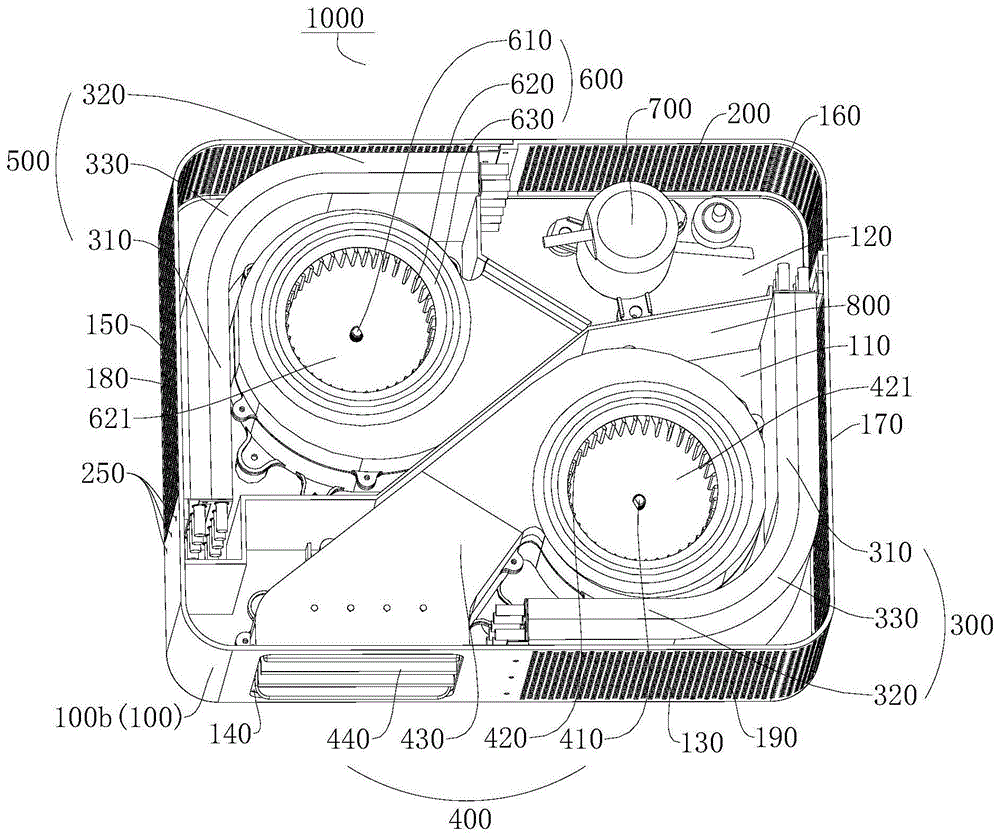
fig. 1 is a schematic structural view of an air conditioner according to an embodiment of the present invention;
fig. 2 is a partial structural schematic view of an air conditioner according to an embodiment of the present invention;
FIG. 3 is an exploded view of a first fan assembly according to one embodiment of the present invention;
FIG. 4 is a schematic structural diagram of a first fan assembly according to one embodiment of the present invention;
fig. 5 is a partial structural schematic view of an air conditioner according to another embodiment of the present invention;
fig. 6 is an exploded view of an air conditioner according to another embodiment of the present invention;
FIG. 7 is a schematic diagram of a base according to one embodiment of the present invention;
FIG. 8 is a schematic structural diagram of an upper shell according to one embodiment of the present invention;
FIG. 9 is a schematic structural diagram of a base according to another embodiment of the present invention;
FIG. 10 is a schematic structural diagram of an upper shell according to another embodiment of the present invention;
FIG. 11 is a schematic structural view of a first heat exchanger according to another embodiment of the present invention;
FIG. 12 is a schematic diagram of a second heat exchanger according to another embodiment of the present invention;
FIG. 13 is a schematic structural view of a first motor or a second motor according to another embodiment of the present invention;
FIG. 14 is a schematic view of the construction of a first volute according to another embodiment of the invention;
FIG. 15 is a schematic structural view of a second volute according to another embodiment of the invention;
fig. 16 is a schematic structural view of a compressor according to another embodiment of the present invention.
Reference numerals:
an air-conditioner (1000) is provided,
a housing 100, a top cover 100a, a base 100b,
a first air duct 110, a first motor fixing seat 111, a third connecting hole 1111, a first supporting boss 112, a fifth connecting hole 1121,
a second air duct 120, a second motor fixing seat 121, a seventh connecting hole 1211, a second supporting boss 122, a ninth connecting hole 1221,
the first air inlet 130, the first air outlet 140, the second air inlet 150, the second air outlet 160, the first sidewall 170, the second sidewall 180, the third sidewall 190, the fourth sidewall 200,
the first support rib 210, the second support rib 220, the third support boss 230, the eleventh coupling hole 231, the sealing rib 240, the first coupling hole 250,
a first heat exchanger 300, a first section 310, a second section 320, an arc section 330, a second connection hole 340,
the first fan assembly 400, the first motor 410, the fourth connecting hole 411, the first wind wheel 420, the first wind wheel inlet 421, the first volute 430, the sixth connecting hole 431, the wind guide assembly 440, the wind guide plate 441, the mounting post 442, the mounting hole 443,
the second heat exchanger (500) is provided with,
a second fan assembly 600, a second motor 610, an eighth connection hole 611, a second wind wheel 620, a second wind wheel inlet 621, a second scroll 630, a tenth connection hole 631,
compressor 700, twelfth connecting hole 710, and middle partition plate 800.
Detailed Description
Reference will now be made in detail to embodiments of the present invention, examples of which are illustrated in the accompanying drawings, wherein like or similar reference numerals refer to the same or similar elements or elements having the same or similar function throughout. The embodiments described below with reference to the accompanying drawings are illustrative only for the purpose of explaining the present invention, and are not to be construed as limiting the present invention.
An air conditioner 1000 according to an embodiment of the present invention is described below with reference to fig. 1 to 16.
As shown in fig. 1 to 6, an air conditioner 1000 according to an embodiment of the present invention includes a case 100, a first heat exchanger 300, a first fan assembly 400, a second heat exchanger 500, a second fan assembly 600, and a compressor 700. The case 100 may provide an installation space for the first heat exchanger 300, the first fan assembly 400, the second heat exchanger 500, the second fan assembly 600, and the compressor 700; the first heat exchanger 300 and the second heat exchanger 500 may be filled with a refrigerant, and the first heat exchanger 300 and the second heat exchanger 500 may refrigerate or heat by vaporization or liquefaction of the refrigerant; the first fan assembly 400 and the second fan assembly 600 may drive airflow movement; the compressor 700 may provide power for a refrigeration cycle of the air conditioner 1000 to output high-temperature and high-pressure gas.
Specifically, referring to fig. 2, the housing 100 defines therein a first air duct 110 and a second air duct 120, and the first air duct 110 and the second air duct 120 are arranged in a horizontal direction. The housing 100 is provided with a first air inlet 130 and a first air outlet 140 communicated with the first air duct 110, the housing 100 is further provided with a second air inlet 150 and a second air outlet 160 communicated with the second air duct 120, the first heat exchanger 300 is arranged in the first air duct 110, and two ends of the first heat exchanger 300 are connected with the housing 100 through fasteners, so that the first heat exchanger 300 can be reliably installed in the housing 100, the first heat exchanger 300 can be conveniently detached from the housing 100, and the maintainability of the first heat exchanger 300 can be improved. The first fan assembly 400 is disposed in the first air duct 110 to drive an air flow from the first air inlet 130 to the first air outlet 140.
The second heat exchanger 500 is arranged in the second air duct 120, one of the first heat exchanger 300 and the second heat exchanger 500 is a condenser, and the other of the first heat exchanger 300 and the second heat exchanger 500 is an evaporator, wherein when the first heat exchanger 300 is a condenser, the second heat exchanger 500 is an evaporator; when the first heat exchanger 300 is an evaporator, the second heat exchanger 500 is a condenser, and the refrigerant may be liquefied and release heat in the condenser, and evaporated and absorb heat in the evaporator, so that the refrigeration cycle of the air conditioner 1000 may be smoothly performed, and here, the first heat exchanger 300 is an evaporator, and the second heat exchanger 500 is a condenser, which is taken as an example for description, and is not to be construed as limiting the present application. Both ends of the second heat exchanger 500 are coupled to the case 100 by fasteners, whereby the second heat exchanger 500 can be reliably installed in the case 100, and installation and removal of the second heat exchanger 500 into and from the case 100 are facilitated, so that the maintainability of the second heat exchanger 500 can be improved.
The second fan assembly 600 is disposed in the second air duct 120 to drive the air flow from the second air inlet 150 to the second air outlet 160. The compressor 700 is disposed in one of the first air duct 110 and the second air duct 120, and the compressor 700, the first heat exchanger 300, and the second heat exchanger 500 form a heat exchange flow path, wherein the compressor 700 transmits a high-temperature and high-pressure refrigerant to the second heat exchanger 500, and the refrigerant is liquefied and releases heat in the second heat exchanger 500, so that the temperature of the airflow outside the second heat exchanger 500 is increased; the liquefied refrigerant flows to the first heat exchanger 300, and the refrigerant is vaporized in the first heat exchanger 300 to absorb heat, so that the temperature of the airflow outside the first heat exchanger 300 is reduced.
It can be understood that, when the air conditioner 1000 cools, the indoor hot air flow enters the first air duct 110 from the first air inlet 130, the hot air flow exchanges heat with the first heat exchanger 300 when passing through the first heat exchanger 300, and enters the first fan assembly 400 after becoming the cold air flow, and the first fan assembly 400 drives the cold air flow to the first air outlet 140, so that the cold air flow can flow from the first air outlet 140 to the indoor space to cool the indoor space; in order to enable the refrigeration cycle of the air conditioner 1000 to operate continuously, the indoor air flow further enters the second air duct 120 from the second air inlet 150, the air flow exchanges heat with the second heat exchanger 500 when passing through the second heat exchanger 500, and then enters the second fan assembly 600 after becoming a hot air flow, the second fan assembly 600 drives the hot air flow to the second air outlet 160, therefore, the hot air flow can flow to the indoor from the second air outlet 160, at this time, a heat pipe can be installed at the second air outlet 160 to guide the hot air flow out of the indoor, and the hot air flow flowing to the indoor can be left untreated, which is not particularly limited herein.
In the related art, most of air conditioners are separated from an internal machine and an external machine, an indoor heat exchanger is arranged in the internal machine, an outdoor heat exchanger is arranged in the external machine, and the air conditioners with the separated internal machine and the external machine are complex to install and need to be punched on walls to destroy home decoration. A small number of indoor heat exchangers and outdoor heat exchangers are simultaneously installed in an integrated air conditioner in a shell, the air duct is complex in design, the size of the air conditioner is large, the occupied indoor area is large when the air conditioner is placed, and the air conditioner is not easy to replace and maintain when the heat exchangers are damaged.
According to the air conditioner 1000 of the embodiment of the invention, the first air duct 110 and the second air duct 120 are horizontally arranged in the casing 100, and the first heat exchanger 300 and the first fan assembly 400 are arranged in the first air duct 110, wherein the first heat exchanger 300 is connected with the casing 100 through a threaded fastener, so that hot air entering the first air duct 110 from the first air inlet 130 can be converted into cold air to be blown out from the first air outlet 140 during refrigeration of the first air duct; the second heat exchanger 500 and the second fan assembly 600 are arranged in the second air duct 120, wherein the second heat exchanger 500 is connected with the casing 100 through a threaded fastener, so that the air flow entering the air duct from the second air inlet 150 can be converted into hot air flow to be blown out from the second air outlet 160 during refrigeration of the first air duct, and smooth operation of refrigeration cycle can be ensured.
According to the air conditioner 1000, the first air duct 110 and the second air duct 120 are arranged on the shell 100, and refrigeration in the first air duct 110 and heating in the second air duct 120 can be conducted without interference, so that the air conditioner 1000 is simple in structure and convenient to install, holes do not need to be drilled in a wall, and the home decoration can be kept complete and attractive. Furthermore, the horizontal arrangement of the first air duct 110 and the second air duct 120 makes the structure of the air conditioner 1000 smaller, and the indoor occupied area can be saved when the air conditioner is placed. In addition, the first and second heat exchangers 300 and 500 are coupled to the case 100 by the screw fasteners, so that the replaceability and the maintainability of the first and second heat exchangers 300 and 500 can be improved.
Further, as shown in fig. 7, 9, and 11-12, the housing 100 may have a first connection hole 250, the first heat exchanger 300 and the second heat exchanger 500 may each have a second connection hole 340, the first connection hole 250 and the second connection hole 340 may correspond one-to-one, and a fastener may be inserted into the first connection hole 250 and the second connection hole 340 to fix the first heat exchanger 300 and the second heat exchanger 500 to the housing 100, respectively, whereby the first heat exchanger 300 and the second heat exchanger 500 are reliably mounted in the housing 100.
In some embodiments of the present invention, referring to fig. 7, the bottom wall of the casing 100 is provided with first support ribs 210 for supporting the first heat exchanger 300 and second support ribs 220 for supporting the second heat exchanger 500, the first support ribs 210 extend along the extending direction of the first heat exchanger 300, and the second support ribs 220 extend along the extending direction of the second heat exchanger 500. It can be understood that the first support rib 210 is provided in the first air duct 110, the second support rib 220 is provided in the second air duct 120, and the first support rib 210 can stably support the first heat exchanger 300, so that the first heat exchanger 300 can be reliably mounted in the housing 100; the second support rib 220 may stably support the second heat exchanger 500 so that the second heat exchanger 500 may be reliably mounted in the case 100.
In some embodiments of the present invention, as shown in fig. 2 and 5, the first heat exchanger 300 and the second heat exchanger 500 are disposed oppositely, so that the layout of the first heat exchanger 300 and the second heat exchanger 500 is reasonable and compact, and the product volume of the air conditioner 1000 can be reduced. The first fan assembly 400 is disposed on a side of the first heat exchanger 300 facing the second heat exchanger 500, and the second fan assembly 600 is disposed on a side of the second heat exchanger 500 facing the first heat exchanger 300, it can be understood that, in the first air duct 110, an air flow flows from a side of the first heat exchanger 300 away from the second heat exchanger 500 to a side of the first heat exchanger 300 facing the second heat exchanger 500, and the first fan assembly 400 disposed on a side of the first heat exchanger 300 facing the second heat exchanger 500 can facilitate driving the air flow to flow from the first air inlet 130 to the first air outlet 140, so that the heat exchange efficiency of the first heat exchanger 300 can be improved; in the second air duct 120, the air flow flows from the side of the second heat exchanger 500 far away from the first heat exchanger 300 to the side of the second heat exchanger 500 facing the first heat exchanger 300, and the second fan assembly 600 is disposed on the side of the second heat exchanger 500 facing the first heat exchanger 300, so that the air flow can be conveniently driven to flow from the second air inlet 150 to the second air outlet 160, and the heat exchange efficiency of the second heat exchanger 500 can be improved.
Further, referring to fig. 2 and 5, the first heat exchanger 300 and the second heat exchanger 500 are identical in shape. Thus, it is possible to facilitate the installation and replacement of the first and second heat exchangers 300 and 500, so that the air conditioner 1000 has good versatility.
According to some embodiments of the present invention, as shown in fig. 2, the first and second heat exchangers 300, 500 each include a first section 310 and a second section 320, the first and second sections 310, 320 being at an angle to each other, and the first and second heat exchangers 300, 500 projecting away from each other. Accordingly, the heat exchange areas of the first heat exchanger 300 and the second heat exchanger 500 can be increased, and the heat exchange efficiency of the first heat exchanger 300 and the second heat exchanger 500 can be improved. Further, the first section 310 and the second section 320 are connected through the arc section 330, so that the first section 310 and the second section 320 can be smoothly connected, the first heat exchanger 300 and the second heat exchanger 500 can be conveniently installed in the shell 100, and the probability that the first heat exchanger 300 and the second heat exchanger 500 are damaged by knocking can be reduced.
In some embodiments of the present invention, as shown in fig. 2, the case 100 includes opposite first and second sidewalls 170 and 180 and opposite third and fourth sidewalls 190 and 200, the third sidewall 190 is connected between one end of the first sidewall 170 and one end of the second sidewall 180, and the fourth sidewall 200 is connected between the other end of the first sidewall 170 and the other end of the second sidewall 180, whereby the first, second, third, and fourth sidewalls 170, 180, 190, and 200 may form an installation space such that the first heat exchanger 300, the first fan assembly 400, the second heat exchanger 500, the second fan assembly 600, and the compressor 700 may be installed in the installation space.
Wherein the first section 310 and the second section 320 of the first heat exchanger 300 are respectively parallel to the first side wall 170 and the third side wall 190, the first section 310 and the second section 320 of the second heat exchanger 500 are respectively parallel to the second side wall 180 and the fourth side wall 200, it should be noted that the first air intake 130 may be disposed at a position on the first side wall 170 and the third side wall 190 corresponding to the first section 310 and the second section 320 of the first heat exchanger 300, and the second air intake 150 may be disposed at a position on the second side wall 180 and the fourth side wall 200 corresponding to the first section 310 and the second section 320 of the second heat exchanger 500, so that air can be taken in from both the first heat exchanger 300 and the second heat exchanger 500 on the casing 100, thereby increasing the heat exchange amount of the air flow with the first heat exchanger 300 and the second heat exchanger 500, and improving the heat exchange efficiency of the first heat exchanger 300 and the second heat exchanger 500.
According to some embodiments of the present invention, as shown in fig. 5 to 6, the first heat exchanger 300 and the second heat exchanger 500 are each formed in a flat plate shape, whereby it is possible to facilitate the manufacture of the first heat exchanger 300 and the second heat exchanger 500, and also to facilitate the installation of the first heat exchanger 300 into the first air duct 110 and the installation of the second heat exchanger 500 into the second air duct 120.
With reference to fig. 5-6, in some embodiments of the present invention, the housing 100 includes the first and second opposite sidewalls 170 and 180, the first heat exchanger 300 is parallel to the first sidewall 170, and the second heat exchanger 500 is parallel to the second sidewall 180, thereby facilitating the arrangement of the first and second heat exchangers 300 and 500 and improving the space utilization of the housing 100.
Further, as shown in fig. 5-6, the first heat exchanger 300 and the second heat exchanger 500 are both vertically disposed and are both disposed adjacent to the inner side wall of the housing 100, and the first air inlet 130 and the second air inlet 150 are both disposed on the side wall of the housing 100, so that the space of the housing 100 can be further effectively utilized, and the first heat exchanger 300 is closer to the first air inlet 130, and the second heat exchanger 500 is closer to the second air inlet 150, so that after air enters, the first heat exchanger 300 and the second heat exchanger 500 can exchange heat with the air flow faster. The first air inlet 130 is opposite to the first heat exchanger 300 and extends along the extending direction of the first heat exchanger 300, and the second air inlet 150 is opposite to the second heat exchanger 500 and extends along the extending direction of the second heat exchanger 500, so that the heat exchange amount of the air flow with the first heat exchanger 300 and the second heat exchanger 500 can be increased, and the heat exchange efficiency of the first heat exchanger 300 and the second heat exchanger 500 can be improved.
According to some embodiments of the present invention, as shown in fig. 5 to 6, the first outlet port 140 and the second outlet port 160 are both disposed on the side wall of the housing 100, the first outlet port 140 is disposed between one end of the first inlet port 130 and one end of the second inlet port 150, and the second outlet port 160 is disposed between the other end of the first inlet port 130 and the other end of the second inlet port 150. It can be understood that the airflow from the first outlet 140 is cold airflow, and the airflow from the second outlet 160 is hot airflow, and the first outlet 140 and the second outlet 160 are spaced apart from each other to reduce the influence of the first outlet 140 and the second outlet 160 on each other.
With reference to fig. 2-6, in some embodiments of the present invention, the first fan assembly 400 includes a first motor 410 and a first wind wheel 420, the first wind wheel 420 is connected to the first motor 410, the first wind wheel 420 is a centrifugal wind wheel, an axis of the centrifugal wind wheel extends in a vertical direction, and both axial ends of the centrifugal wind wheel are configured as a first wind wheel inlet 421. The first motor 410 can drive the first wind wheel 420 to rotate, the first wind wheel 420 rotates to drive airflow to flow from the first air inlet 130 to the first air outlet 140, and the air inlets at the two axial ends of the centrifugal wind wheel can enable more cold airflow to flow to the first air outlet 140 and further flow to the indoor space, so that more airflow is subjected to heat exchange with the first heat exchanger 300, and therefore the refrigeration effect of the air conditioner 1000 can be improved.
Further, as shown in fig. 7-10, a first motor fixing seat 111 for fixing the first motor 410 is disposed on a top wall or a bottom wall of the first air duct 110, and the first motor fixing seat 111 can support the first motor 410, so that the first motor 410 is reliably mounted in the housing 100. Further, referring to fig. 7 and 13, the first motor fixing base 111 has a third coupling hole 1111, the first motor 410 has a fourth coupling hole 411, and the third coupling hole 1111 and the fourth coupling hole 411 correspond to each other one by one and are coupled by a fastening member, so that the first motor 410 can be reliably mounted in the housing 100, and the first motor 410 can be easily mounted in the housing 100 and also easily detached from the housing 100, thereby improving the maintainability of the first motor 410.
For example, in the example shown in fig. 7, the first motor fixing base 111 is provided on the bottom wall of the first air duct 110, and in the examples shown in fig. 9 and 10, the first motor fixing base 111 is provided on the top wall of the first air duct 110.
According to some embodiments of the present invention, referring to fig. 2-6, the first fan assembly 400 further includes a first volute 430, the first volute 430 being disposed within the first air duct 110, and the first wind wheel 420 being disposed within the first volute 430. Therefore, the first volute 430 can support the first wind wheel 420 and also protect the first wind wheel 420, so that the first wind wheel 420 can be conveniently installed in the first wind tunnel 110. In addition, the first scroll 430 may also provide a guide for the airflow so that the airflow smoothly flows to the first air outlet 140.
Further, as shown in fig. 7-10, a plurality of spaced first support bosses 112 for supporting and fixing the first scroll case 430 are provided on a bottom wall or a top wall of the first air duct 110, and the first scroll case 430 is connected to the first support bosses 112 by fasteners. Accordingly, the first support boss 112 can reliably support the first scroll case 430, so that the first scroll case 430 has a gap with the bottom wall or the top wall of the casing 100 to allow airflow, and thus airflow can enter the first wind wheel 420 from both sides of the first wind wheel 420, increasing the air output of the first wind wheel 420.
Further, referring to fig. 7 and 14, the first support boss 112 has fifth connection holes 1121, the first scroll case 430 has sixth connection holes 431, and the fifth connection holes 1121 and the sixth connection holes 431 are in one-to-one correspondence and connected by a fastener, whereby the first scroll case 430 can be reliably mounted in the housing 100, and the mounting of the first scroll case 430 into the housing 100 and the removal of the first scroll case 430 from the housing 100 are facilitated, so that the maintainability of the first scroll case 430 can be improved.
For example, in the example shown in fig. 7, the first support bosses 112 are provided on the bottom wall of the first air duct 110, and in the examples shown in fig. 9 and 10, the first support bosses 112 are provided on the top wall of the first air duct 110.
The first support boss 112 and the first motor fixing seat 111 may be located on the top wall at the same time. The first supporting boss 112 and the first motor fixing seat 111 may also be located on the bottom wall at the same time. One of the first support boss 112 and the first motor fixing seat 111 may be located on the top wall, and the other may be located on the bottom wall, that is, when the first support boss 112 is located on the top wall, the first motor fixing seat 111 is located on the bottom wall; when the first support boss 112 is located at the bottom wall, the first motor fixing seat 111 is located at the top wall, and thus, flexibility of arrangement of the first support boss 112 and the first motor fixing seat 111 in the housing 100 may be improved.
With reference to fig. 2 and 5-6, in some embodiments of the present invention, the second fan assembly 600 includes a second motor 610 and a second wind wheel 620, the second wind wheel 620 is connected to the second motor 610, the second wind wheel 620 is a centrifugal wind wheel, an axis of the centrifugal wind wheel extends in a vertical direction, and both axial ends of the centrifugal wind wheel are configured as a second wind wheel inlet 621. The second motor 610 can drive the second wind wheel 620 to rotate, the second wind wheel 620 can drive airflow to flow from the second air inlet 150 to the second air outlet 160 by rotating, and the air inlets at the two axial ends of the centrifugal wind wheel can enable more cold airflow to flow to the second air outlet 160 and enable more airflow to exchange heat with the second heat exchanger 500, so that the working efficiency of the refrigeration cycle system can be improved.
Further, as shown in fig. 7-10, a second motor fixing seat 121 for fixing the second motor 610 is disposed on a top wall or a bottom wall of the second air duct 120, and the second motor fixing seat 121 can support the second motor 610, so that the second motor 610 is reliably mounted in the housing 100. Further, referring to fig. 7 and 13, the second motor holder 121 has a seventh connecting hole 1211, the second motor 610 has an eighth connecting hole 611, and the seventh connecting hole 1211 and the eighth connecting hole 611 correspond to each other one by one and are connected by a fastener, so that the second motor 610 can be reliably mounted in the housing 100, and the second motor 610 can be easily mounted in the housing 100 and also easily dismounted from the housing 100, thereby improving the maintainability of the second motor 610.
For example, in the example shown in fig. 7, the second motor fixing base 121 is provided on the bottom wall of the second air duct 120, and in the example shown in fig. 9 and 10, the second motor fixing base 121 is provided on the bottom wall of the second air duct 120.
According to some embodiments of the present invention, referring to fig. 2 and 5-6, second fan assembly 600 further includes a second volute 630, second volute 630 being disposed within second wind tunnel 120, and second wind wheel 620 being disposed within second volute 630. Therefore, the second volute 630 may support the second wind wheel 620 and also protect the second wind wheel 620, so as to facilitate the installation of the second wind wheel 620 in the first wind tunnel 110. In addition, the second volute 630 may also provide a guide for the airflow so that the airflow smoothly flows to the second air outlet 160.
Further, as shown in fig. 7-10, a plurality of spaced apart second support bosses 122 for supporting and fixing the second volute 630 are provided on a bottom wall or a top wall of the second duct 120, and the second volute 630 and the second support bosses 122 are connected by fasteners. Therefore, the second support boss 122 can reliably support the second volute 630, so that the second volute 630 has a gap with the bottom wall or the top wall of the casing 100 to allow airflow to pass through, and thus the airflow can enter the second wind wheel 620 from both sides of the second wind wheel 620, and the air output of the second wind wheel 620 is increased.
Further, referring to fig. 7 and 15, the second support boss 122 has a ninth coupling hole 1221, the second scroll casing 630 has a tenth coupling hole 631, and the ninth coupling hole 1221 and the tenth coupling hole 631 correspond one-to-one and are coupled by a fastener, whereby the second scroll casing 630 can be securely mounted in the housing 100, and the second scroll casing 630 can be easily mounted in the housing 100 and also easily dismounted from the housing 100, so that the maintainability of the second scroll casing 630 can be improved.
For example, in the example shown in fig. 7, the second support bosses 122 are provided on the bottom wall of the second air duct 120, and in the examples shown in fig. 9 and 10, the second support bosses 122 are provided on the bottom wall of the second air duct 120.
The second support boss 122 and the second motor fixing seat 121 may be located on the top wall of the casing 100 at the same time. The second supporting boss 122 and the second motor fixing seat 121 may also be located at the bottom wall of the casing 100 at the same time. One of the second support boss 122 and the second motor fixing seat 121 may be located on the top wall of the casing 100, and the other is located on the bottom wall of the casing 100, that is, when the second support boss 122 is located on the top wall of the casing 100, the second motor fixing seat 121 is located on the bottom wall of the casing 100; when the second support boss 122 is located at the bottom wall of the casing 100, the second motor fixing seat 121 is located at the top wall of the casing 100, and thus, flexibility in arrangement of the second support boss 122 and the second motor fixing seat 121 in the casing 100 may be improved.
Here, referring to fig. 7 to 10, the first motor 410 and the second motor 610 may be simultaneously located at the top wall of the housing 100. The first motor 410 and the second motor 610 may be located at the same time on the bottom wall of the housing 100. The first motor 410 and the second motor 610 may be located on the top wall of the housing 100, and the other one may be located on the bottom wall of the housing 100, that is, when the first motor 410 is located on the top wall of the housing 100, the second motor 610 is located on the bottom wall of the housing 100; when the first motor 410 is located at the bottom wall of the housing 100, the second motor 610 is located at the top wall of the housing 100, and thus, flexibility in arranging the first motor 410 and the second motor 610 within the housing 100 may be improved.
Here, referring to fig. 7-10, the first and second volutes 430 and 630 may be located at the top wall of the housing 100 at the same time. First volute 430 and second volute 630 may also be located at the same time on the bottom wall of housing 100. One of the first volute 430 and the second volute 630 may be located on the top wall of the housing 100, and the other may be located on the bottom wall of the housing 100, that is, when the first volute 430 is located on the top wall of the housing 100, the second volute 630 is located on the bottom wall of the housing 100; when the first scroll case 430 is located at the bottom wall of the housing 100, the second scroll case 630 is located at the top wall of the housing 100, and thus, flexibility in arranging the first and second scroll cases 430 and 630 within the housing 100 may be improved.
As shown in fig. 1-6, in some embodiments of the present invention, a wind guiding assembly 440 is disposed at the first wind outlet 140. The air guiding assembly 440 can adjust the direction and the air output at the first air outlet 140, so as to improve the comfort of the air conditioner 1000.
Further, the wind guiding assembly 440 may include a plurality of wind guiding plates 441, and each wind guiding plate 441 is rotatably connected to the first spiral case 430, so that the wind outlet direction and the wind outlet amount at the first wind outlet 140 may be conveniently adjusted. The two ends of each air deflector 441 are provided with mounting posts 442, the first volute 430 is provided with a plurality of mounting holes 443 corresponding to the mounting posts 442, the mounting posts 442 are in one-to-one correspondence with the mounting holes 443, and the mounting posts 442 are rotatably disposed in the mounting holes 443, so that the air deflector 441 can rotate relative to the first volute 430, and the air outlet direction and the air outlet amount at the first air outlet 140 can be adjusted.
In one example as shown in FIG. 2, the compressor 700 may be disposed within the second air duct 120, downstream of the second fan assembly 600 in the airflow direction, of the compressor 700. Therefore, when the second fan assembly 600 blows the airflow to the second air outlet 160, the waste heat generated by the compressor 700 can be taken away, the working efficiency of the compressor 700 can be improved, and the service life of the compressor 700 can be prolonged by cooling the compressor 700.
In another example as shown in FIG. 5, the compressor 700 may be disposed within the first air chute 110, with the compressor 700 disposed upstream of the first fan assembly 400 in the direction of airflow flow. Therefore, the arrangement of the compressor 700 is facilitated, and when the air flow flows in the first air duct 110, the waste heat generated by the compressor 700 can be taken away, so that the working efficiency of the compressor 700 is improved.
Further, as shown in fig. 7 to 10, a plurality of spaced third supporting bosses 230 for supporting and fixing the compressor 700 are provided on the bottom wall of the casing 100, the compressor 700 is connected to the third supporting bosses 230 by fasteners, and the third supporting bosses 230 can reliably support the compressor 700, so that the compressor 700 is installed in the casing 100. Further, referring to fig. 7 and 16, the third support boss 230 has an eleventh coupling hole 231, and the compressor 700 has a twelfth coupling hole 710, and the eleventh coupling holes 231 and the twelfth coupling holes 710 correspond to each other one by one and are coupled by a fastener, whereby the compressor 700 can be reliably mounted in the casing 100, and the compressor 700 can be easily mounted in the casing 100 and the compressor 700 can be easily removed from the casing 100, thereby improving the maintainability of the compressor 700.
According to some embodiments of the present invention, as shown in fig. 7 to 10, the housing 100 includes a base 100b and a top cover 100a, and the base 100b and the top cover 100a are connected by a fastener to define the first air duct 110 and the second air duct 120 together, wherein, fig. 7 and 8 are an exemplary base 100b and top cover 100a, and fig. 9 and 10 are another exemplary base 100b and top cover 100a, the first air duct 110 may provide an installation space for the first heat exchanger 300 and the first fan assembly 400, so that the first heat exchanger 300 and the first fan assembly 400 may stably perform a cooling function; the second air duct 120 may provide an installation space for the second heat exchanger 500 and the second fan assembly 600, so that the second heat exchanger 500 and the second fan assembly 600 may stably perform a heat exchange function.
In some embodiments of the present invention, in combination with fig. 2 and 5-6, the air conditioner 1000 further includes a middle partition 800, and the middle partition 800 is disposed in the base 100b to divide the housing 100 into the first air duct 110 and the second air duct 120. Therefore, in the first air duct 110, the first heat exchanger 300 can stably perform a refrigeration function, in the second air duct 120, the second heat exchanger 500 can stably perform heat exchange, and the first air duct 110 and the second air duct 120 are formed on one shell 100, so that the air conditioner 1000 is simple in structure and convenient to install, does not need to be punched on a wall, and can keep the home decoration complete and attractive.
According to some embodiments of the present invention, as shown in fig. 8 and 10, a sealing rib 240 is disposed on a lower surface of the top cover 100a, and the sealing rib is opposite to and abutted against the middle partition 800, the first heat exchanger 300, and the second heat exchanger 500, so that the sealing rib 240 can seal the middle partition 800, the first heat exchanger 300, and the second heat exchanger 500, and the first air duct 110 and the second air duct 120 have better sealing performance, so that air flow between the first air duct 110 and the second air duct 120 is difficult to circulate, and thus mutual interference between the first air duct 110 and the second air duct 120 can be avoided, and the refrigeration performance of the air conditioner 1000 can be improved.
In the description herein, references to the description of the term "one embodiment," "some embodiments," "an illustrative embodiment," "an example," "a specific example," or "some examples" or the like mean that a particular feature, structure, material, or characteristic described in connection with the embodiment or example is included in at least one embodiment or example of the invention. In this specification, the schematic representations of the terms used above do not necessarily refer to the same embodiment or example. Furthermore, the particular features, structures, materials, or characteristics described may be combined in any suitable manner in any one or more embodiments or examples.
While embodiments of the invention have been shown and described, it will be understood by those of ordinary skill in the art that: various changes, modifications, substitutions and alterations can be made to the embodiments without departing from the principles and spirit of the invention, the scope of which is defined by the claims and their equivalents.