CN113931516A - Holding pole standing device - Google Patents
Holding pole standing device Download PDFInfo
- Publication number
- CN113931516A CN113931516A CN202111439289.3A CN202111439289A CN113931516A CN 113931516 A CN113931516 A CN 113931516A CN 202111439289 A CN202111439289 A CN 202111439289A CN 113931516 A CN113931516 A CN 113931516A
- Authority
- CN
- China
- Prior art keywords
- pole
- frame body
- holding
- jacking
- fixed
- Prior art date
- Legal status (The legal status is an assumption and is not a legal conclusion. Google has not performed a legal analysis and makes no representation as to the accuracy of the status listed.)
- Pending
Links
Images



Classifications
-
- E—FIXED CONSTRUCTIONS
- E04—BUILDING
- E04H—BUILDINGS OR LIKE STRUCTURES FOR PARTICULAR PURPOSES; SWIMMING OR SPLASH BATHS OR POOLS; MASTS; FENCING; TENTS OR CANOPIES, IN GENERAL
- E04H12/00—Towers; Masts or poles; Chimney stacks; Water-towers; Methods of erecting such structures
- E04H12/34—Arrangements for erecting or lowering towers, masts, poles, chimney stacks, or the like
Landscapes
- Engineering & Computer Science (AREA)
- Architecture (AREA)
- Civil Engineering (AREA)
- Structural Engineering (AREA)
- Jib Cranes (AREA)
Abstract
The utility model provides a pole setting-up device, through the installation on the jacking support body lift by crane the coaster, the inboard waist hoop device of installing of jacking support body, the last symmetry of jacking support body is equipped with two sets of assembly pulleys, and the head end portion of haulage rope is fixed in the top frame of jacking support body and passes first movable pulley downwards, upwards passes the second subsequently and turns to the fixed pulley, passes the third in the rearmost direction fixed pulley downwards, draws forth to pulling promotion power device, and mechanical promotion pole setting-up realizes the assemblage of pole. This hold pole device of standing up is applicable to the condition extensively, and the device is light-duty, and easy dismouting, simple structure and not attached power equipment's suspension hold pole flip-chip hoisting device can standardize hold pole process of standing up simultaneously, reduces the safe risk of standing up, improves the efficiency of construction, is worth popularizing and applying.
Description
Technical Field
The invention belongs to the technical field of pole rising, and particularly relates to a pole rising device.
Background
The power transmission line channel inevitably passes through mountainous areas due to the characteristics of geographical environment and energy distribution of China. The power transmission line iron tower assemblage in the mountainous area is limited by factors such as terrain, traffic, environmental water conservation and the like, most mountain tower positions cannot be assembled mechanically, and the traditional suspension holding pole assemblage process is still adopted at present.
The iron tower structure of the ultra-high voltage and ultra-high voltage transmission line has various types, the length of the holding pole selected according to the structure characteristics and the weight distribution of the tower is usually 27-45 m, the holding pole has high risk when being erected, the terrain of a mountain area is steep, and the erection difficulty of the holding pole is further increased. For standardizing the pole setting up technology, reducing the safe risk of setting up, specially develop light-dutyization, easy dismouting, simple structure, utilize current tower tool hank to grind and the mechanical lifting pole setting up device of rope as power, filled the blank of suspension pole setting up tool.
The existing suspension holding pole generally adopts the following methods:
(1) integral stand up
Firstly, the falling single holding pole stands up: the standing speed is fast, and it is light to use, but the system of standing up is unstable, and the risk of standing up is great, also faces the difficulty of single pole self standing up simultaneously in mountain region.
Standing the herringbone holding rod: the herringbone holding pole is a holding pole standing mode which is commonly used, the use is convenient, the standing length of the holding pole is limited, the longer the holding pole is, the more complex the standing system is, and the greater the risk is. Meanwhile, the requirement on the terrain for the stand of the holding pole is high, the holding pole needs to have a lengthening condition, and the holding pole is difficult to stand for the full length in mountain areas.
Erecting a crane: the method has the advantages of high standing speed and low construction risk, but has high requirements on fields and transportation, is limited by terrains, and is not suitable for standing in mountain areas.
(2) Erecting by upright installation
The standing speed is high, the operation is convenient, but the standing safety risk is large, and the holding pole is prohibited to adopt a normal installation method in the current safety regulation.
(3) Partially erected and then inverted
When the mountainous terrain condition is poor, the small holding pole is utilized to assemble for 18-24 meters, and then the lower section tower body of the large holding pole or the small holding pole is utilized to reversely assemble the holding pole to a preset height. The method is mostly used for assembling the holding pole in the mountain, but when the lower root of the extra-high voltage iron tower is large and the difference of the high leg and the low leg of the mountain is large, the large holding pole cannot be assembled or cannot meet the requirement of assembling and hoisting the lower tower body, so that the holding pole cannot be inverted.
At present, the tower position paths of ultrahigh voltage and extra-high voltage transmission lines are mostly positioned in dense forests in mountains, the tower footing is designed in an all-dimensional high-low leg mode, the terrain is steep, the environment of an iron tower assembly operation surface is poor, the main material of the iron tower is single and long, the weight is large, and the method for erecting the suspension holding pole is not suitable. Meanwhile, a special assembly construction tool is not used in the flip-chip method, and related process guidance rules are not elaborated in detail, so that the field construction operation method is various, constructors are easy to operate in violation, the safety risk is greatly increased, and safety accidents are frequent.
The suspension holding pole tower assembling process is still the mainstream of the current power transmission and transformation project construction, mountain projects can face the problem of difficult holding pole erection, the erection of the overlong holding pole is a high-risk operation, group death and group injury are easily caused by carelessness, and under the current safety situation, the problem of safe erection of the overlong holding pole is very necessary to solve.
Disclosure of Invention
The invention aims to provide a pole erecting device which is suitable for a mountain suspension pole erecting device, reduces the erecting safety risk and fills the blank of a suspension pole assembling tool aiming at the defects of the prior art.
In order to solve the technical problems, the invention adopts the technical scheme that:
a holding pole erecting device comprises a jacking frame body and a waist hoop device arranged on the inner side of the jacking frame body, wherein the waist hoop device comprises connecting rods which are fixedly and vertically connected in sequence and guide wheels which are rotatably arranged at two ends of the connecting rods, and the fixing parts of adjacent connecting rods are also provided with connecting holes and are connected with the jacking frame body through matched connecting springs;
the jacking frame body is also symmetrically provided with two groups of pulley blocks, each group of pulley block comprises a first movable pulley arranged in the middle of the bottom end, a second steering fixed pulley arranged on the side of a top corner and a third steering fixed pulley corresponding to the side of a bottom corner, the head end part of the traction rope is fixed on the top end frame of the jacking frame body, downwards passes through the first movable pulley, upwards passes through the second steering fixed pulley, and finally downwards passes through the third steering fixed pulley, and is led out to a traction lifting power device;
the first movable pulley below in both sides is connected respectively on the adjustable shelf establishes the lift plate in jacking support body bottom, along with the first movable pulley of haulage rope atress along with treating the pole rebound of embracing that promotes, the jacking back that targets in place, embraces the pole and fixes in jacking support body top, and the first movable pulley of haulage rope pine returns the bottom and prepares one section down and embraces the pole jacking and be connected with one section last pole to this is accomplished whole armful pole jacking and is stood repeatedly.
And the upper end part of the jacking frame body is also provided with a small-sized suspension arm for assisting in lifting the holding pole.
The jacking frame body is of a rectangular frame structure, and anchor plates for stabilizing the jacking frame body are fixedly arranged at the upper and lower four corners of the jacking frame body and are fixed through tensioning of the arranged stay wire ropes.
And three groups of fourth fixed pulleys for assisting the holding rod to pull into the jacking frame body are arranged on the small-sized suspension arm.
The upper end of the jacking frame body is fixedly provided with a supporting platform for mounting the small-sized suspension arm, and the supporting platform is provided with a fastening threaded hole and fixes a bottom support of the small-sized suspension arm through a fastening bolt correspondingly arranged.
The invention has the beneficial effects that:
(1) this pole setting-up device lifts by crane the coaster through the installation on the jacking support body, and the inboard waist hoop device of installing of jacking support body still the symmetry is equipped with two sets of assembly pulleys on the jacking support body, and the head end portion of haulage rope is fixed in the top frame of jacking support body and passes first movable pulley downwards, upwards passes the second and turns to the fixed pulley afterwards, passes the third and turns to the fixed pulley downwards at the latest, draws forth to pulling and promotes power device, and mechanical promotion pole setting-up realizes the assemblage of pole.
(2) The upper and lower four corners of the jacking frame body are fixedly provided with anchor plates for stabilizing the jacking frame body, and the anchor plates are tensioned and fixed through the arranged stay wire ropes, and the ground is pulled to fix the whole lifting frame; simultaneously, the small-size davit of jacking support body top installation sets three groups and is used for assisting the pole of embracing and pull the fourth fixed pulley that gets into the jacking support body, improves pole of embracing lifting efficiency, increases the security of embracing the pole head and standing up.
(3) The holding pole standing device provided by the invention is used in mountainous areas, reduces overhead operation, has a simple, portable and detachable holding pole jacking system, enables the holding pole to be assembled more safely and controllably, and saves cost.
(4) The pole-holding standing device is wide in application condition, light in weight, easy to assemble and disassemble, simple in structure and free of power equipment, can standardize the pole-holding standing process, reduces the standing safety risk, improves the construction efficiency, and is worthy of popularization and application.
Drawings
Fig. 1 is a front view of a jack body;
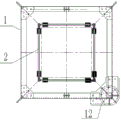
FIG. 2 is a top view of the jack body;
figure 3 is a schematic structural view of a waist cuff apparatus;
FIG. 4 is an overall assembly view of the present invention;
fig. 5 is a top view of the present invention.
Detailed Description
The following description of the embodiments of the present invention is provided for illustrative purposes, and other advantages and effects of the present invention will become apparent to those skilled in the art from the present disclosure.
The present invention provides a pole raising apparatus as shown in figures 1 to 5.
The holding pole erecting device comprises a jacking frame body 1 and a waist hoop device 2 arranged on the inner side of the jacking frame body 1, wherein the waist hoop device 2 comprises connecting rods 21 which are sequentially and fixedly and vertically connected and guide wheels 22 which are rotatably arranged at two ends of the connecting rods 21, and the fixing parts of the adjacent connecting rods 21 are also provided with connecting holes and are connected with the jacking frame body 1 through matched connecting springs;
still the symmetry is equipped with two sets of assembly pulleys 3 on the jacking support body 1, and every assembly pulley of group all including locate the bottom in the middle of the first movable pulley 31 with locate the second of top edge side and turn to the fixed pulley 32 and correspond the bottom edge side the third and turn to the fixed pulley 33, the head end of haulage rope 4 is fixed in the top frame of jacking support body 1 and passes first movable pulley 31 downwards, upwards passes second and turns to the fixed pulley 32 afterwards, passes third and turns to the fixed pulley 33 downwards at last, draws forth to drawing and promoting power device.
The first movable pulley 31 below in both sides is connected respectively in the adjustable shelf and is established on the lifting plate of 1 bottom of jacking support body, along with the first movable pulley 31 of haulage rope 4 atress along with treating that the pole 5 of embracing that promotes upwards moves, the jacking back that targets in place, it is fixed in 1 top of jacking support body to embrace the pole, and haulage rope 4 loosens first movable pulley 31 and returns the bottom and prepare 5 jacking of one section armful pole down and be connected with one section armful pole to this is accomplished whole armful pole jacking and is stood repeatedly.
Because first section armful of pole top is heavier, and it is more difficult that jacking support body is put into in the manpower transport, so still erect the small-size davit 6 that is used for supplementary promotion armful of pole at 1 upper end of jacking support body, small-size davit 6 sets up three groups of fourth fixed pulleys for first section armful of pole machinery pulls, the supplementary lift that gets into of manpower, and small-size davit 6 can be dismantled with the upper end of jacking support body 1 through connecting bolt and is connected.
In this embodiment, the jacking frame body 1 is a rectangular frame structure, and the upper and lower four corners are both fixedly provided with anchor plates 11 for stabilizing the jacking frame body 1 and are fixed by pulling with the arranged stay wires. In order to conveniently install the small-sized suspension arm, a supporting platform 12 for installing the small-sized suspension arm is fixedly arranged at the upper end part of the jacking frame body 1, a fastening threaded hole is formed in the supporting platform 12, and a bottom support of the small-sized suspension arm 6 is fixed through a fastening bolt correspondingly arranged; and three groups of fourth fixed pulleys for assisting the holding rod to pull into the jacking frame body are arranged on the small-sized suspension arm.
According to the pole-clasping erecting device, a hoisting tackle is installed on a jacking frame body, a waist hoop device is installed on the inner side of the jacking frame body 1, two groups of pulley blocks 3 are symmetrically arranged on the jacking frame body 1, the head end part of a traction rope 4 is fixed on a top end frame of the jacking frame body 1 and downwards penetrates through a first movable pulley 31, then upwards penetrates through a second steering fixed pulley 32, finally downwards penetrates through a third steering fixed pulley 33 and is led out to a traction lifting power device, and routing mechanically lifts a pole-clasping pole according to the diagram shown in figure 1 to realize the erection of the pole-clasping pole; the upper and lower four corners of the jacking frame body are fixedly provided with anchor plates for stabilizing the jacking frame body, and the anchor plates are tensioned and fixed through the arranged stay wire ropes, and the ground stay wires are tied to fix the whole lifting frame. Simultaneously, the small-size davit of jacking support body 1 top installation improves and embraces pole lifting efficiency, increases the security of embracing the pole head to rise.
The derrick erecting device provided by the invention is used in mountainous areas, overhead operation is reduced, a derrick jacking system is simple, the derrick erection is safer and more controllable, and the cost is saved, taking 750 × 34m derrick erection as an example, 4 aloft operators and 4 ground operators are reduced, the erection efficiency is improved, the single erection time is shortened by half a day, the derrick erecting device is used for erecting by one derrick by one set, the labor cost is saved by 2400 yuan, the surplus labor cost of a single project is reduced by 24 ten thousand yuan, and the erection safety is effectively ensured.
In addition, the pole-holding standing device is wide in application condition, light in weight, easy to assemble and disassemble, simple in structure and free of power equipment, and meanwhile, the pole-holding standing process can be standardized, the standing safety risk is reduced, the construction efficiency is improved, and the pole-holding standing device is worthy of popularization and application. At present, the construction projects of our company include white crane beach-Jiangsu and Nanjing-Changsha projects, and white crane beach-Zhejiang projects to be started, most of towers are located in mountainous regions, the terrain conditions are poor, 750 and 900-section holding poles are needed, the length of the holding poles is 34-45 meters, and the holding pole assembly requirements in mountainous regions exist. Meanwhile, the industry has a great deal of demands, besides the assembly application, when important spanning is performed such as high-speed rail, high-speed and power line spanning, a lattice type spanning frame is often adopted, when the terrain is limited, the main body holding pole of the spanning frame is erected to meet the demands of a lifting device, and the large-scale application prospect is achieved.
The foregoing shows and describes the general principles, essential features, and advantages of the invention. It will be understood by those skilled in the art that the present invention is not limited to the embodiments described above, which are given by way of illustration of the principles of the present invention, and that various changes and modifications may be made without departing from the spirit and scope of the invention as defined by the appended claims. The scope of the invention is defined by the appended claims and equivalents.
In the description of the present invention, it is to be understood that the terms "front", "rear", "left", "right", "center", etc., indicate orientations or positional relationships based on those shown in the drawings, and are used only for convenience in describing the present invention and for simplicity in description, but do not indicate or imply that the device or element being referred to must have a particular orientation, be constructed and operated in a particular orientation, and thus, are not to be construed as limiting the scope of the present invention.
Claims (5)
Priority Applications (1)
| Application Number | Priority Date | Filing Date | Title |
|---|---|---|---|
| CN202111439289.3A CN113931516A (en) | 2021-11-30 | 2021-11-30 | Holding pole standing device |
Applications Claiming Priority (1)
| Application Number | Priority Date | Filing Date | Title |
|---|---|---|---|
| CN202111439289.3A CN113931516A (en) | 2021-11-30 | 2021-11-30 | Holding pole standing device |
Publications (1)
| Publication Number | Publication Date |
|---|---|
| CN113931516A true CN113931516A (en) | 2022-01-14 |
Family
ID=79288653
Family Applications (1)
| Application Number | Title | Priority Date | Filing Date |
|---|---|---|---|
| CN202111439289.3A Pending CN113931516A (en) | 2021-11-30 | 2021-11-30 | Holding pole standing device |
Country Status (1)
| Country | Link |
|---|---|
| CN (1) | CN113931516A (en) |
Cited By (1)
| Publication number | Priority date | Publication date | Assignee | Title |
|---|---|---|---|---|
| CN116750666A (en) * | 2023-04-14 | 2023-09-15 | 国网江苏省电力有限公司宿迁供电分公司 | An adjustable telescopic floor-standing pole device suitable for small spaces |
Citations (5)
| Publication number | Priority date | Publication date | Assignee | Title |
|---|---|---|---|---|
| WO2017016369A1 (en) * | 2015-07-27 | 2017-02-02 | 中国电力科学研究院 | Tower crane for assembling power transmission tower |
| CN106495063A (en) * | 2016-12-19 | 2017-03-15 | 王洪英 | Suspension hoist engine lifting pole device in a kind of distance type |
| CN112832579A (en) * | 2020-12-29 | 2021-05-25 | 国网湖南省电力有限公司 | A suspension pole-mounted derrick type flip-chip hoisting system and its application method |
| CN214456405U (en) * | 2021-02-24 | 2021-10-22 | 国网湖南省电力有限公司 | A gantry-type suspension holding pole flip-mounted lifting frame device |
| CN216240042U (en) * | 2021-11-30 | 2022-04-08 | 河南送变电建设有限公司 | A pole holding device |
-
2021
- 2021-11-30 CN CN202111439289.3A patent/CN113931516A/en active Pending
Patent Citations (5)
| Publication number | Priority date | Publication date | Assignee | Title |
|---|---|---|---|---|
| WO2017016369A1 (en) * | 2015-07-27 | 2017-02-02 | 中国电力科学研究院 | Tower crane for assembling power transmission tower |
| CN106495063A (en) * | 2016-12-19 | 2017-03-15 | 王洪英 | Suspension hoist engine lifting pole device in a kind of distance type |
| CN112832579A (en) * | 2020-12-29 | 2021-05-25 | 国网湖南省电力有限公司 | A suspension pole-mounted derrick type flip-chip hoisting system and its application method |
| CN214456405U (en) * | 2021-02-24 | 2021-10-22 | 国网湖南省电力有限公司 | A gantry-type suspension holding pole flip-mounted lifting frame device |
| CN216240042U (en) * | 2021-11-30 | 2022-04-08 | 河南送变电建设有限公司 | A pole holding device |
Cited By (1)
| Publication number | Priority date | Publication date | Assignee | Title |
|---|---|---|---|---|
| CN116750666A (en) * | 2023-04-14 | 2023-09-15 | 国网江苏省电力有限公司宿迁供电分公司 | An adjustable telescopic floor-standing pole device suitable for small spaces |
Similar Documents
| Publication | Publication Date | Title |
|---|---|---|
| CN102359303B (en) | Extra-high voltage common circuit iron tower assembling method | |
| CN105529648B (en) | Hydraulic pressure assembled crossing frame | |
| CN102359302B (en) | Extra-high voltage large-span iron tower assembling method | |
| CN104276514B (en) | Installation method of ground self-balancing pole | |
| CN203377546U (en) | High speed railway spanning construction apparatus | |
| CN205955358U (en) | Group's tower device of interior floated armful of pole of acting as go -between | |
| CN205489264U (en) | Hydraulic pressure assembled crossing structure | |
| CN109687349B (en) | Bypass cable wiring method and special equipment thereof | |
| CN105421859A (en) | Electricity grid telegraph pole erecting device and construction method | |
| CN216341336U (en) | Adjustable inverted frame structure of 750 x 750mm cross-section holding rod system | |
| CN103132766A (en) | Truss for lifting power transmission line tower connecting leg and erection method | |
| CN109236012B (en) | Method for hoisting power transmission line T-shaped guyed tower | |
| CN106368493A (en) | Two-arm hydraulic drive-in type hard capping lattice type crossing frame | |
| CN102535939A (en) | Inversely assembling process for standing stay wire V-type tower | |
| CN110510527A (en) | Installation system of high slope variable cross-section slope precast block and construction method thereof | |
| CN202544476U (en) | Tower crane type holding rod | |
| CN114352033B (en) | Steel structure beam and column support mounting construction method | |
| CN216240042U (en) | A pole holding device | |
| CN204150970U (en) | Seat ground self-balancing pole | |
| CN213596814U (en) | Movable three-dimensional spanning multi-purpose suspension bridge construction platform | |
| CN204609435U (en) | The auxiliary tower that hoists of emergent repairing tower | |
| CN209276035U (en) | A kind of self-supporting superelevation Lift-on/Lift-off System | |
| CN203359890U (en) | Small-sized electric pole hoisting device | |
| CN206189985U (en) | Both arms hydraulic pressure propulsion type lattice formula crossing structure that binds firmly | |
| CN110748140A (en) | Track beam hanging basket special for stepped curtain wall |
Legal Events
| Date | Code | Title | Description |
|---|---|---|---|
| PB01 | Publication | ||
| PB01 | Publication | ||
| SE01 | Entry into force of request for substantive examination | ||
| SE01 | Entry into force of request for substantive examination | ||
| RJ01 | Rejection of invention patent application after publication |
Application publication date: 20220114 |
|
| RJ01 | Rejection of invention patent application after publication |