CN113894606B - High-rigidity heavy-cutting gantry machining equipment - Google Patents
High-rigidity heavy-cutting gantry machining equipment Download PDFInfo
- Publication number
- CN113894606B CN113894606B CN202111253436.8A CN202111253436A CN113894606B CN 113894606 B CN113894606 B CN 113894606B CN 202111253436 A CN202111253436 A CN 202111253436A CN 113894606 B CN113894606 B CN 113894606B
- Authority
- CN
- China
- Prior art keywords
- fixedly connected
- plate
- workbench
- base
- water
- Prior art date
- Legal status (The legal status is an assumption and is not a legal conclusion. Google has not performed a legal analysis and makes no representation as to the accuracy of the status listed.)
- Active
Links
Images


Classifications
-
- B—PERFORMING OPERATIONS; TRANSPORTING
- B23—MACHINE TOOLS; METAL-WORKING NOT OTHERWISE PROVIDED FOR
- B23Q—DETAILS, COMPONENTS, OR ACCESSORIES FOR MACHINE TOOLS, e.g. ARRANGEMENTS FOR COPYING OR CONTROLLING; MACHINE TOOLS IN GENERAL CHARACTERISED BY THE CONSTRUCTION OF PARTICULAR DETAILS OR COMPONENTS; COMBINATIONS OR ASSOCIATIONS OF METAL-WORKING MACHINES, NOT DIRECTED TO A PARTICULAR RESULT
- B23Q11/00—Accessories fitted to machine tools for keeping tools or parts of the machine in good working condition or for cooling work; Safety devices specially combined with or arranged in, or specially adapted for use in connection with, machine tools
- B23Q11/0042—Devices for removing chips
- B23Q11/0064—Devices for removing chips by using a magnetic or electric field
-
- B—PERFORMING OPERATIONS; TRANSPORTING
- B23—MACHINE TOOLS; METAL-WORKING NOT OTHERWISE PROVIDED FOR
- B23Q—DETAILS, COMPONENTS, OR ACCESSORIES FOR MACHINE TOOLS, e.g. ARRANGEMENTS FOR COPYING OR CONTROLLING; MACHINE TOOLS IN GENERAL CHARACTERISED BY THE CONSTRUCTION OF PARTICULAR DETAILS OR COMPONENTS; COMBINATIONS OR ASSOCIATIONS OF METAL-WORKING MACHINES, NOT DIRECTED TO A PARTICULAR RESULT
- B23Q11/00—Accessories fitted to machine tools for keeping tools or parts of the machine in good working condition or for cooling work; Safety devices specially combined with or arranged in, or specially adapted for use in connection with, machine tools
- B23Q11/0042—Devices for removing chips
- B23Q11/0067—Devices for removing chips chip containers located under a machine or under a chip conveyor
-
- Y—GENERAL TAGGING OF NEW TECHNOLOGICAL DEVELOPMENTS; GENERAL TAGGING OF CROSS-SECTIONAL TECHNOLOGIES SPANNING OVER SEVERAL SECTIONS OF THE IPC; TECHNICAL SUBJECTS COVERED BY FORMER USPC CROSS-REFERENCE ART COLLECTIONS [XRACs] AND DIGESTS
- Y02—TECHNOLOGIES OR APPLICATIONS FOR MITIGATION OR ADAPTATION AGAINST CLIMATE CHANGE
- Y02P—CLIMATE CHANGE MITIGATION TECHNOLOGIES IN THE PRODUCTION OR PROCESSING OF GOODS
- Y02P70/00—Climate change mitigation technologies in the production process for final industrial or consumer products
- Y02P70/10—Greenhouse gas [GHG] capture, material saving, heat recovery or other energy efficient measures, e.g. motor control, characterised by manufacturing processes, e.g. for rolling metal or metal working
Abstract
The invention discloses high-rigidity heavy-cutting gantry machining equipment, and belongs to the field of gantry machining. A high-rigidity heavy-cutting gantry machining device comprises a base, wherein a workbench is fixedly connected to the base, and supporting plates are fixedly connected to the left side and the right side of the workbench; the automatic cleaning device is characterized by further comprising a motor fixedly connected to the supporting plate, wherein a screw rod is fixedly connected to the output end of the motor, the screw rod is rotatably connected to the supporting plate, a moving plate is connected to the screw rod in a threaded manner, a spray head is fixedly connected to the moving plate, and collecting boxes are fixedly connected to the front side and the rear side of the workbench; the iron scrap cleaning machine is simple to use and convenient to operate, the screw rod drives the spray head on the movable plate to move to wash iron scraps on the workbench, the labor intensity of manual cleaning is reduced, the convenience and the efficiency of cleaning are improved, meanwhile, the magnetic ring adsorbs residual fine scraps on the workbench, the balance degree of the work placed on the workbench is improved, and the machining accuracy is improved.
Description
Technical Field
The invention relates to the technical field of gantry cutting machining, in particular to high-rigidity heavy-cutting gantry machining equipment.
Background
The gantry machining center is provided with a gantry frame and a horizontal long lathe bed, the gantry frame comprises upright posts and a cross beam arranged between the upright posts, a spindle box is arranged on the cross beam, and a cutter is arranged on the spindle box and is used for machining a workpiece; the gantry machining center can be used for milling, grinding and the like of the workpiece.
In the prior art, when an existing gantry machining center cleans a workpiece after machining, a worker holds a spray gun type to clean the gantry manually, the cleaning speed is low, the cleaning efficiency is low, scrap iron splashes around after being punched, the trouble of subsequent cleaning is increased, fine scraps are easy to remain on a workbench of the machining center after cleaning, the workpiece is placed in unevenness during subsequent machining, and the machining precision of the workpiece is influenced during cutting, so that the invention provides high-rigidity heavy-cutting gantry machining equipment.
Disclosure of Invention
The invention aims to solve the problems that in the prior art, when a worker holds a spray gun type to manually clean, the cleaning speed is low, the cleaning efficiency is low, scrap iron splashes around after being washed, the subsequent cleaning is troublesome, fine scraps are easy to remain on a worktable of a machining center after the cleaning is finished, the workpiece is placed in an uneven state during the subsequent machining, and the machining precision of the workpiece is influenced during the cutting, and provide high-rigidity heavy-cutting gantry machining equipment.
In order to achieve the purpose, the invention adopts the following technical scheme:
the high-rigidity heavy-cutting gantry machining equipment comprises a base, wherein a workbench is fixedly connected to the base, and supporting plates are fixedly connected to the left side and the right side of the workbench; the automatic cleaning device is characterized by further comprising a motor fixedly connected to the supporting plate, wherein a screw rod is fixedly connected to the output end of the motor, the screw rod is rotatably connected to the supporting plate, a moving plate is connected to the screw rod in a threaded manner, a spray head is fixedly connected to the moving plate, and collecting boxes are fixedly connected to the front side and the rear side of the workbench; the base is provided with a water supply assembly, and the water supply assembly is connected with the spray head; the rotary table comprises a rotary base, wherein the rotary base is fixedly connected to the movable plate, a rotary rod is rotatably connected to the rotary base, a magnetic ring and a gear are fixedly connected to the rotary rod, a rack is fixedly connected to the base, and the gear is meshed with the rack.
In order to supply water conveniently, preferably, the water supply assembly comprises a water tank, a water pump and a water outlet pipe, the water tank is fixedly connected to the bottom of the base, the water pump is fixedly connected to the water tank, the water pump is connected with the water tank, and the water pump is connected with the spray head through the water outlet pipe.
In order to improve the utilization of water, preferably, a water outlet groove is formed in the collecting box, a filter plate is fixedly connected to the water outlet groove, and the water outlet groove is connected with the water tank through a water discharge pipe.
In order to collect waste residues conveniently, preferably, a discharge groove is formed in the collection box and is located on the right side of the water outlet groove, the base is fixedly connected with a collection box, the discharge groove is communicated with the collection box, and the movable plate is fixedly connected with a scraper which is connected in the collection box in a sliding mode.
In order to prevent water from entering the discharge groove, a baffle plate is preferably arranged in the collecting box and is positioned on the left side of the discharge groove.
In order to improve the capacity of the collecting box, preferably, an eccentric wheel is fixedly connected to the screw rod, a rotating sleeve is rotatably connected to the eccentric wheel, a piston rod is rotatably connected to the rotating sleeve, a piston plate is rotatably connected to the piston rod, and the piston plate is slidably connected to the collecting box.
In order to clean the waste materials conveniently, preferably, a discharge chute is formed in the collection box, a clamping sleeve is fixedly connected to the discharge chute, and a baffle is connected to the clamping sleeve in a sliding mode.
In order to conveniently clean the scraps on the magnetic ring, preferably, the support plate is slidably connected with a slide bar, the slide bar is fixedly connected with a deslagging plate, the slide bar is sleeved with a spring, and two ends of the spring are respectively abutted against the support plate and the deslagging plate.
In order to collect the scraps, preferably, a material receiving box is fixedly connected to the base and located below the deslagging plate.
In order to improve the washing effect, preferably, there are two groups of the spray heads, and the two groups of the spray heads correspond to the workbench.
Compared with the prior art, the invention provides high-rigidity heavy-cutting gantry machining equipment which has the following beneficial effects:
1. this high rigidity heavy-duty cutting longmen processing equipment washes in the face of the workstation through the shower nozzle subtend, washes the iron fillings that the cutting produced on the workstation and collects in collecting the box, reduces the intensity of labour of artifical clearance, improves the convenience of clearance, reduces artifical handheld spray gun and washes and cause iron fillings to splash and be difficult to the clearance, improves the security and the efficiency of clearance.
2. This high rigidity heavy-duty cutting longmen processing equipment adsorbs the remaining tiny piece of workstation surface through the magnetic ring, reduces tiny piece and remains on the workstation, improves the level and smooth of placing of work piece on the workstation, improves the precision of work piece processing.
3. This high rigidity heavy cutting longmen processing equipment drives the magnetosphere through the dwang on the gear and rotates, rotates through the magnetosphere and adsorbs tiny iron fillings, reduces the piece and piles up too much on the magnetosphere, improves the absorptive effect of magnetosphere.
Drawings
FIG. 1 is a schematic three-dimensional structural diagram I of a high-rigidity heavy-cutting gantry machining device provided by the invention;
FIG. 2 is a schematic three-dimensional structural diagram of a high-rigidity heavy-cutting gantry machining device provided by the invention;
FIG. 3 is a schematic structural diagram of a front view of a high-rigidity heavy-cutting gantry machining device provided by the invention;
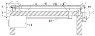
FIG. 4 is a front cross-sectional view of a high rigidity heavy cutting gantry machining apparatus according to the present invention;
FIG. 5 is a schematic structural diagram of a high rigidity heavy cutting gantry machining apparatus in a top view;
FIG. 6 is a schematic structural diagram of a high-rigidity heavy-cutting gantry machining apparatus as viewed from the right;
FIG. 7 is a schematic structural diagram of part A in FIG. 3 of a high rigidity heavy cutting gantry machining apparatus according to the present invention;
FIG. 8 is a schematic structural diagram of part B in FIG. 4 of a high rigidity heavy cutting gantry machining apparatus according to the present invention;
FIG. 9 is a schematic structural diagram of a portion C in FIG. 4 of a high rigidity heavy cutting gantry machining apparatus according to the present invention;
FIG. 10 is a schematic structural diagram of an eccentric wheel and a collection box of the high-rigidity heavy-cutting gantry machining equipment provided by the invention;
fig. 11 is a schematic structural diagram of a moving plate and a spray head of a high-rigidity heavy-cutting gantry machining device provided by the invention.
In the figure: 1. a base; 101. a water outlet groove; 102. a discharge chute; 2. a work table; 3. a support plate; 4. a motor; 5. a screw rod; 6. moving the plate; 7. a spray head; 8. a collection box; 9. rotating; 10. rotating the rod; 11. a magnetic coil; 12. a gear; 13. a rack; 14. a water tank; 15. a water pump; 16. a water outlet pipe; 17. a filter plate; 18. a drain pipe; 19. a collection box; 20. a squeegee; 21. a barrier plate; 22. an eccentric wheel; 23. rotating the sleeve; 24. a piston rod; 25. a piston plate; 26. a ferrule; 27. a baffle plate; 28. a slide bar; 29. a slag removal plate; 30. a spring; 31. a material receiving box.
Detailed Description
The technical solutions in the embodiments of the present invention will be clearly and completely described below with reference to the drawings in the embodiments of the present invention, and it is obvious that the described embodiments are only a part of the embodiments of the present invention, and not all of the embodiments.
In the description of the present invention, it is to be understood that the terms "upper", "lower", "front", "rear", "left", "right", "top", "bottom", "inner", "outer", and the like, indicate orientations or positional relationships based on the orientations or positional relationships shown in the drawings, are merely for convenience in describing the present invention and simplifying the description, and do not indicate or imply that the device or element being referred to must have a particular orientation, be constructed and operated in a particular orientation, and thus, should not be construed as limiting the present invention.
Example 1:
referring to fig. 1, 2, 3, 4, 5, 6, 7, 8 and 11, the high-rigidity heavy cutting gantry machining equipment comprises a base 1, wherein a workbench 2 is fixedly connected to the base 1, and supporting plates 3 are fixedly connected to the left side and the right side of the workbench 2; the automatic cleaning device is characterized by further comprising a motor 4 fixedly connected to the supporting plate 3, wherein the output end of the motor 4 is fixedly connected with a screw rod 5, the screw rod 5 is rotatably connected to the supporting plate 3, a moving plate 6 is connected to the screw rod 5 in a threaded manner, a spray head 7 is fixedly connected to the moving plate 6, and collecting boxes 8 are fixedly connected to the front side and the rear side of the workbench 2; the base 1 is provided with a water supply assembly which is connected with the spray head 7; swivel mount 9, fixed connection is on moving plate 6, and wherein, swivel mount 9 goes up the rotation and is connected with dwang 10, fixedly connected with magnetosphere 11 and gear 12 on the dwang 10, fixedly connected with rack 13 on the base 1, and gear 12 links to each other with the meshing of rack 13, and shower nozzle 7 has two sets ofly, and two sets of shower nozzles 7 are corresponding with workstation 2.
In the invention, after the cutting processing of the workpiece is finished, the workpiece is taken out from the workbench 2, the water supply assembly supplies water to the spray heads 7, the water is sprayed out from the spray heads 7 to wash the workbench 2, two groups of spray heads 7 are respectively arranged at two sides of the movable plate 6 in an inclined downward manner, the water outlet directions of the two groups of spray heads 7 face to the middle of the workbench 2, then the motor 4 is started, the motor 4 drives the screw rods 5 to rotate, two groups of screw rods 5 are arranged, the two groups of screw rods 5 are rotationally connected with each other through a transmission belt, the screw rods 5 drive the movable plate 6 to move, the movable plate 6 drives the spray heads 7 to wash the workbench 2, the spray heads 7 face to the workbench 2 for washing, scrap iron generated by cutting on the workbench 2 is collected in the collecting box 8, the labor intensity of manual cleaning is reduced, the convenience of high-cleaning is improved, and the phenomenon that the scrap iron is difficult to clean due to the washing of a manual spray gun is reduced, improve the security and the efficiency of clearance, the movable plate 6 drives the magnetosphere 11 on the dwang 10 when removing simultaneously and removes, adsorb 2 remaining tiny pieces in surface of workstation through magnetosphere 11, it remains on workstation 2 to reduce tiny piece, improve the level and smooth that the work piece was placed on workstation 2, improve the precision of work piece processing, it is further, movable plate 6 removes and drives gear 12 and mesh rotation on rack 13, gear 12 drives magnetosphere 11 through dwang 10 and rotates, rotate through magnetosphere 11 and adsorb tiny iron fillings, it is too much to reduce the piece to pile up on magnetosphere 11, improve the absorptive effect of magnetosphere 11.
Example 2:
referring to fig. 1, 2, 3, 4, 5, 6, 7, 8 and 11, the high-rigidity heavy-cutting gantry machining equipment comprises a water supply assembly, a water tank 14, a water pump 15 and a water outlet pipe 16, wherein the water tank 14 is fixedly connected to the bottom of a base 1, the water pump 15 is fixedly connected to the water tank 14, the water pump 15 is connected with a spray head 7 through the water outlet pipe 16, a water outlet groove 101 is formed in a collecting box 8, a filter plate 17 is fixedly connected to the water outlet groove 101, and the water outlet groove 101 is connected with the water tank 14 through a water outlet pipe 18.
Compared with the embodiment 1, further, by starting the water pump 15, the cleaning liquid is pumped out from the water tank 14 by the water pump 15, the cleaning liquid is sprayed out from the spray head 7 through the water outlet pipe 16 to wash the workbench 2, meanwhile, after the cleaning liquid and the iron filings enter the collecting box 8, the cleaning liquid and the iron filings enter the water outlet pipe 18 through the water outlet groove 101, the cleaning liquid and the iron filings enter the water tank 14 through the water outlet pipe 18 for recycling, the waste of the cleaning liquid is reduced, the utilization efficiency is improved, the filter plate 17 is arranged on the water outlet groove 101, and the iron filings are prevented from entering the water tank 14.
Example 3:
referring to fig. 1, 2, 3, 4, 5, 6, 7, 8, 9, 10 and 11, the high-rigidity heavy-cutting gantry machining equipment comprises a collecting box 8, wherein a discharge groove 102 is formed in the collecting box 8, the discharge groove 102 is located on the right side of a water outlet groove 101, a collecting box 19 is fixedly connected to a base 1, the discharge groove 102 is communicated with the collecting box 19, a moving plate 6 is fixedly connected with a scraper 20, the scraper 20 is slidably connected in the collecting box 8, a blocking plate 21 is arranged in the collecting box 8, and the blocking plate 21 is located on the left side of the discharge groove 102.
Compare with embodiment 1, further, when the movable plate 6 removed, drive scraper blade 20 and slide in collecting box 8, promote falling the iron fillings in collecting box 8 through scraper blade 20, then get into collection box 19 through the row's of collecting box in 8 material groove 102 and collect, the convenience of collecting the iron fillings is improved, reduce the intensity of labour of artifical clearance, it is further that row's material groove 102 left side is provided with baffler 21, obstruct the washing liquid through baffler 21, prevent that the washing liquid from getting into collection box 19, the security of using is improved, scraper blade 20 is the rubber material, conveniently strike off row's of material groove 102 in to iron fillings through baffler 21.
Example 4:
referring to fig. 1, fig. 2, fig. 3, fig. 4, fig. 5, fig. 6, fig. 9 and fig. 10, a high-rigidity heavy-cutting gantry machining device comprises an eccentric wheel 22 fixedly connected to a screw rod 5, a rotating sleeve 23 rotatably connected to the eccentric wheel 22, a piston rod 24 rotatably connected to the rotating sleeve 23, a piston plate 25 rotatably connected to the piston rod 24, the piston plate 25 slidably connected to a collecting box 19, a discharge chute formed in the collecting box 19, a cutting sleeve 26 fixedly connected to the discharge chute, and a baffle plate 27 slidably connected to the cutting sleeve 26.
Compared with the embodiment 1, further, the screw 5 drives the eccentric wheel 22 to rotate when rotating, the eccentric wheel 22 drives the rotating sleeve 23 to rotate, the rotating sleeve 23 drives the piston plate 25 to do reciprocating piston motion in the collecting box 19 through the piston rod 24, and when too much scrap iron is collected in the collecting box 19, the scrap iron is extruded through the piston plate 25, so that the quantity of the collecting box 19 for collecting the scrap iron is increased, and the manual cleaning frequency is reduced.
Example 5:
referring to fig. 1, 2, 3, 4, 5, 7 and 8, the high-rigidity heavy-cutting gantry machining equipment comprises a sliding rod 28, a deslagging plate 29 and a spring 30, wherein the sliding rod 28 is connected to a supporting plate 3 in a sliding mode, the deslagging plate 29 is fixedly connected to the sliding rod 28, the spring 30 is sleeved on the sliding rod 28, two ends of the spring 30 abut against the supporting plate 3 and the deslagging plate 29 respectively, a material receiving box 31 is fixedly connected to a base 1, and the material receiving box 31 is located below the deslagging plate 29.
Compare with embodiment 1, further, to 2 clearance completions backs of workstation, motor 4 reversal drives movable plate 6 through lead screw 5 and resets, and the magnetosphere 11 on the dwang 10 rotates and offsets with slagging-off board 29, strikes off through the tiny piece that slagging-off board 29 on the magnetosphere 11, falls into and connects the workbin 31 in and collect, reduces the manual work and to the trouble of magnetosphere 11 clearance, improves the convenience of using.
Example 6:
a high-rigidity heavy-cutting gantry machining device comprises an induction module, a central control module and an instruction module;
the induction module comprises a metal sensor and a thrust inductor, and the metal sensor and the thrust inductor are arranged on the moving plate;
the central control module is provided with a central control device, and the central control device is arranged on the base and connected with the induction module;
the instruction module comprises a motor and a water pump, the motor and the water pump are connected with the central control device, and the motor rotating speed and the water pump power are regulated and controlled by receiving an instruction of the central control device.
It should be noted that, this device is for realizing how much controlling the speed of motor drive movable plate and the power that the water pump drew water according to work piece cutting process iron fillings volume, set up the response module, well accuse module and instruction module, acquire the volume of metal iron fillings and movable plate through the response module and push away the resistance, give the well accuse device of well accuse module with iron fillings volume and resistance signal transmission, well accuse module is according to iron fillings volume and resistance signal regulation and control instruction module, control motor speed and water pump power, increase motor speed and water pump power when iron fillings volume and resistance are great, vice versa, realize producing the function that iron fillings volume in time regulates and control motor drive movable plate water spray rate and water pump water spray power according to work piece cutting process. The resistance is larger, specifically, if the resistance is larger than a preset resistance threshold, the resistance is larger, and the resistance threshold may be set by a person skilled in the art according to actual needs, or may be set dynamically in an automated manner.
The iron scrap cleaning machine is simple to use and convenient to operate, the screw rod 5 drives the spray head 7 on the movable plate 6 to move to wash iron scraps on the workbench 2, the labor intensity of manual cleaning is reduced, the convenience and the efficiency of cleaning are improved, meanwhile, the magnetic ring 11 is used for adsorbing fine scraps remained on the workbench 2, the balance degree of the work placed on the workbench 2 is improved, and the machining accuracy is improved.
The above description is only for the preferred embodiment of the present invention, but the scope of the present invention is not limited thereto, and any person skilled in the art should be considered to be within the technical scope of the present invention, and the technical solutions and the inventive concepts thereof according to the present invention should be equivalent or changed within the scope of the present invention.
In the present invention, the term "plurality" means two or more unless explicitly defined otherwise. The terms "mounted," "connected," "fixed," and the like are to be construed broadly, and for example, "connected" may be a fixed connection, a removable connection, or an integral connection; "coupled" may be direct or indirect through an intermediary. The specific meanings of the above terms in the present invention can be understood by those skilled in the art according to specific situations.
In the description of the present specification, the description of "one embodiment," "some embodiments," "specific embodiments," etc., means that a particular feature, structure, material, or characteristic described in connection with the embodiment or example is included in at least one embodiment or example of the invention. In this specification, the schematic representations of the terms used above do not necessarily refer to the same embodiment or example. Furthermore, the particular features, structures, materials, or characteristics described may be combined in any suitable manner in any one or more embodiments or examples.
The above description is only a preferred embodiment of the present invention and is not intended to limit the present invention, and various modifications and changes may be made by those skilled in the art. Any modification, equivalent replacement, or improvement made within the spirit and principle of the present invention should be included in the protection scope of the present invention.
Claims (4)
1. The high-rigidity heavy-cutting gantry machining equipment comprises a base (1), and is characterized in that a workbench (2) is fixedly connected to the base (1), and supporting plates (3) are fixedly connected to the left side and the right side of the workbench (2);
the automatic cleaning device is characterized by further comprising a motor (4) fixedly connected to the supporting plate (3), wherein the output end of the motor (4) is fixedly connected with a screw rod (5), the screw rod (5) is rotatably connected to the supporting plate (3), a moving plate (6) is in threaded connection with the screw rod (5), a spray head (7) is fixedly connected to the moving plate (6), and collecting boxes (8) are fixedly connected to the front side and the rear side of the workbench (2);
a water supply assembly is arranged on the base (1) and is connected with the spray head (7);
the rotary seat (9) is fixedly connected to the moving plate (6), wherein the rotary seat (9) is rotatably connected with a rotating rod (10), the rotating rod (10) is fixedly connected with a magnetic ring (11) and a gear (12), the base (1) is fixedly connected with a rack (13), and the gear (12) is meshed with the rack (13);
a discharge groove (102) is formed in the collecting box (8), the discharge groove (102) is located on the right side of the water outlet groove (101), the base (1) is fixedly connected with a collecting box (19), the discharge groove (102) is communicated with the collecting box (19), the moving plate (6) is fixedly connected with a scraper (20), and the scraper (20) is connected in the collecting box (8) in a sliding mode;
a blocking plate (21) is arranged in the collecting box (8), and the blocking plate (21) is positioned on the left side of the discharging groove (102);
the slag removing device is characterized in that a sliding rod (28) is connected onto the supporting plate (3) in a sliding mode, a slag removing plate (29) is fixedly connected onto the sliding rod (28), a spring (30) is sleeved on the sliding rod (28), and two ends of the spring (30) are respectively abutted against the supporting plate (3) and the slag removing plate (29);
the water supply assembly comprises a water tank (14), a water pump (15) and a water outlet pipe (16), the water tank (14) is fixedly connected to the bottom of the base (1), the water pump (15) is fixedly connected to the water tank (14), the water pump (15) is connected with the water tank (14), and the water pump (15) is connected with the spray head (7) through the water outlet pipe (16);
a water outlet groove (101) is formed in the collecting box (8), a filter plate (17) is fixedly connected to the water outlet groove (101), and the water outlet groove (101) is connected with a water tank (14) through a water discharge pipe (18);
the automatic feeding device is characterized in that an eccentric wheel (22) is fixedly connected onto the screw rod (5), a rotating sleeve (23) is rotatably connected onto the eccentric wheel (22), a piston rod (24) is rotatably connected onto the rotating sleeve (23), a piston plate (25) is rotatably connected onto the piston rod (24), and the piston plate (25) is slidably connected onto the collecting box (19).
2. The high-rigidity heavy cutting gantry machining equipment as claimed in claim 1, wherein a discharge chute is formed in the collection box (19), a clamping sleeve (26) is fixedly connected to the discharge chute, and a baffle plate (27) is slidably connected to the clamping sleeve (26).
3. A high rigidity heavy cutting gantry processing apparatus as claimed in claim 1, wherein the base (1) is fixedly connected with a material receiving box (31), and the material receiving box (31) is located below the slag removing plate (29).
4. A high rigidity heavy cutting gantry machining apparatus according to claim 1, wherein there are two sets of said nozzles (7), and two sets of said nozzles (7) correspond to the table (2).
Priority Applications (1)
| Application Number | Priority Date | Filing Date | Title |
|---|---|---|---|
| CN202111253436.8A CN113894606B (en) | 2021-10-27 | 2021-10-27 | High-rigidity heavy-cutting gantry machining equipment |
Applications Claiming Priority (1)
| Application Number | Priority Date | Filing Date | Title |
|---|---|---|---|
| CN202111253436.8A CN113894606B (en) | 2021-10-27 | 2021-10-27 | High-rigidity heavy-cutting gantry machining equipment |
Publications (2)
| Publication Number | Publication Date |
|---|---|
| CN113894606A CN113894606A (en) | 2022-01-07 |
| CN113894606B true CN113894606B (en) | 2022-07-12 |
Family
ID=79026921
Family Applications (1)
| Application Number | Title | Priority Date | Filing Date |
|---|---|---|---|
| CN202111253436.8A Active CN113894606B (en) | 2021-10-27 | 2021-10-27 | High-rigidity heavy-cutting gantry machining equipment |
Country Status (1)
| Country | Link |
|---|---|
| CN (1) | CN113894606B (en) |
Family Cites Families (6)
| Publication number | Priority date | Publication date | Assignee | Title |
|---|---|---|---|---|
| JP6599016B2 (en) * | 2016-09-09 | 2019-10-30 | 株式会社牧野フライス製作所 | Machine Tools |
| CN209970236U (en) * | 2019-03-21 | 2020-01-21 | 广州通发智能装备股份有限公司 | Iron scrap removing device for gantry machining center |
| CN213315440U (en) * | 2020-09-10 | 2021-06-01 | 林伸杰 | Waste paper recycling and classifying equipment |
| CN214349836U (en) * | 2021-01-26 | 2021-10-08 | 山东熙盛元数控科技有限公司 | Planer-type milling machine convenient to adjust |
| CN214351197U (en) * | 2021-02-04 | 2021-10-08 | 肖小娟 | Chip washing device of machining center |
| CN113369540A (en) * | 2021-06-28 | 2021-09-10 | 惠州市金越精密机械有限公司 | Gantry type multifunctional numerical control drilling machine |
-
2021
- 2021-10-27 CN CN202111253436.8A patent/CN113894606B/en active Active
Also Published As
| Publication number | Publication date |
|---|---|
| CN113894606A (en) | 2022-01-07 |
Similar Documents
| Publication | Publication Date | Title |
|---|---|---|
| CN213888232U (en) | Drilling machine convenient to waste recycling | |
| CN108202263B (en) | Rapid chip removal method for numerical control lathe | |
| CN114289770A (en) | High-precision numerical control milling machine | |
| CN113894606B (en) | High-rigidity heavy-cutting gantry machining equipment | |
| CN112775461A (en) | Drilling equipment is used in processing of general machine part | |
| CN219005732U (en) | Anti-blocking grinding machine | |
| CN216461763U (en) | Novel numerical control lathe | |
| CN216178895U (en) | Numerical control machine tool convenient to clearance piece | |
| CN214109794U (en) | Cutter grinding device for machining | |
| CN114260627A (en) | Multi-face gantry machining center and multifunctional welding machine tool | |
| CN213945790U (en) | Speed reducer worm wheel processing clean-up equipment | |
| CN218800865U (en) | High-precision part machining machine tool with chip removing mechanism | |
| CN214922249U (en) | Fixing base for installing gantry machining center | |
| CN214080448U (en) | Milling machine processing garbage collection device | |
| CN216729948U (en) | Wire cutting device is used in processing of accurate spare part | |
| CN219170315U (en) | Work feeding device of discharging end face milling machine | |
| CN210436888U (en) | Portable work platform of engraver | |
| CN218776080U (en) | Numerical control machine tool convenient for placing parts | |
| CN217453174U (en) | Machine tool convenient to clean and used for machining bearing | |
| CN218518249U (en) | Lathe with deslagging structure | |
| CN211489706U (en) | Radial drill convenient to clearance waste material | |
| CN217858980U (en) | Scrap collecting structure based on milling machine for part machining | |
| CN218856624U (en) | Automatic production device for numerical control lathe accessories | |
| CN215431560U (en) | Excess material recovery device for lathe machining | |
| CN217491389U (en) | Automobile part spraying device with waste material collecting function |
Legal Events
| Date | Code | Title | Description |
|---|---|---|---|
| PB01 | Publication | ||
| PB01 | Publication | ||
| SE01 | Entry into force of request for substantive examination | ||
| SE01 | Entry into force of request for substantive examination | ||
| TA01 | Transfer of patent application right | ||
| TA01 | Transfer of patent application right |
Effective date of registration: 20220620 Address after: 523777 No. 63, Xintai Road, xinmalian village, Dalang Town, Dongguan City, Guangdong Province Applicant after: DONGGUAN BAOKE PRECISION MACHINERY CO.,LTD. Applicant after: Hubei Baoke Intelligent Equipment Co.,Ltd. Address before: 523797 No. 63, Xintai Road, xinmalian village, Dalang Town, Dongguan City, Guangdong Province Applicant before: DONGGUAN BAOKE PRECISION MACHINERY CO.,LTD. |
|
| GR01 | Patent grant | ||
| GR01 | Patent grant |