Disclosure of Invention
In order to solve the technical problem or at least partially solve the technical problem, the application provides a switching power supply control chip and a system with a protection function, and aims to solve the problems that the heat dissipation effect is poor, the service life of the chip is shortened, and even the chip is directly damaged.
In a first aspect, the present application provides a switching power supply control chip with a protection function, including:
a control chip;
the control chip is arranged in the safety protection device so as to realize protection on the control chip;
wherein the safety shield apparatus comprises: the radiating module comprises an upper shell, a lower shell and a radiating assembly, wherein the upper shell is detachably mounted on the lower shell, and a containing cavity for mounting the control chip is formed between the lower shell and the upper shell;
the heat dissipation assembly includes: fixed plate, motor and flabellum, the fixed plate sets up the inside of epitheca, just the both ends of fixed plate respectively with the both sides limit fixed connection of epitheca, the motor is fixed on the fixed plate, just the output of motor is equipped with the orientation the pivot of inferior valve, be connected with the flabellum in the pivot, the louvre that is used for accelerating heat dissipation is offered to inferior valve side one side.
Preferably, the top end of the upper shell is provided with an opening communicated with the accommodating cavity, and the opening is provided with a dust screen.
Preferably, the safety shield apparatus further comprises: the pressing plate is arranged in the containing cavity, the control chip is installed on the surface of the pressing plate, a plurality of through holes used for accelerating heat dissipation are formed in the pressing plate, and the through holes are evenly distributed.
Preferably, the safety shield apparatus further comprises: a clamping assembly for clamping the control chip, the clamping assembly comprising: a first clamping plate, a second clamping plate, a fixed column and an adjusting column,
a limiting strip is arranged on the outer peripheral side of the pressing plate, one end of the adjusting column is connected with the limiting strip on one side edge of the pressing plate, and the other end of the adjusting column is connected with the first clamping plate;
the fixed column is positioned on the opposite side of the adjusting column, one end of the fixed column is fixedly connected to the limiting strip, and the other end of the fixed column is fixedly connected with the second clamping plate;
first splint with be formed with between the second splint and be used for the installation control chip's installation position, through adjust the post regulation first splint stretch to the position of second splint, it is right to realize the size in installation position is adjusted, just first splint with the surface that the second splint faced each other is equipped with the rubber pad.
Preferably, the adjustment post comprises a first threaded post, a second threaded post and a threaded tube,
one end of the first threaded column is fixedly connected with the limiting strip, and the other end of the first threaded column is connected with one end of the threaded pipe;
one end of the second threaded column is fixedly connected with the first clamping plate, and the other end of the second threaded column is connected with the other end of the threaded pipe;
and a hexagonal prism used for adjusting the threaded pipe is arranged outside the threaded pipe.
Preferably, the inner parts of the two ends of the threaded pipe are respectively provided with an internal thread matched with the first threaded column or the second threaded column, and the first threaded column and the second threaded column have the same specification and size.
Preferably, an elastic piece is arranged below the pressing plate, one end of the elastic piece is connected with the bottom of the lower shell, and the other end of the elastic piece is connected with the lower surface of the pressing plate.
Preferably, the bottom of the lower shell is provided with a notch, the elastic part is arranged inside the notch, the length of the elastic part is greater than the depth of the notch, and the diameter of the elastic part is smaller than that of the notch.
In a second aspect, the present application provides a switching power supply control system, comprising: an electric energy input detection module, an electric energy output detection module, a switch power supply control module, a switch key module, a heat dissipation module, a driving module, a feedback module and the switch power supply control chip with the protection function as described in the first aspect,
the input end of the switch power supply control module is connected with the output end of the electric energy input detection module, and the output end of the switch power supply control module is connected with the input end of the electric energy output detection module;
the input end of the switch power supply control chip is connected with the output end of the electric energy output detection module, and the output end of the switch power supply control chip is connected with the input end of the driving module, the output end of the feedback module and the output end of the switch key module;
the output end of the driving module is connected with the input end of the heat dissipation module and the input end of the feedback module.
Preferably, the heat dissipation module includes: a controller and peripheral circuit, a pulse width modulation circuit, an output drive circuit, a protection circuit and a fault indication circuit,
the output ends of the controller and the peripheral circuit are connected with the input end of the driving circuit and the input end of the pulse width modulation circuit, and the input ends of the controller and the peripheral circuit are connected with the output end of the protection circuit and the output end of the fault indication circuit; and the output end of the output driving circuit is used for being connected with a motor.
Compared with the prior art, the technical scheme provided by the embodiment of the application has the following advantages:
(1) the input end of the motor is electrically connected with the output end of the external power supply to drive the rotating shaft to rotate, so that the fan blades connected with the rotating shaft are driven to rotate, the outer surface of the chip is blown, the temperature of the control chip is reduced, and the cooling effect is achieved; meanwhile, the through holes and the heat dissipation holes are formed in one sides of the pressing plate and the lower shell respectively, so that the heat dissipation in the accommodating cavity can be effectively accelerated, and the chip can be controlled to be cooled quickly;
(2) carry out the chucking through set up the chucking subassembly on the clamp plate and fix with control chip for can be when the shell overturns, control chip can not appear dropping, and in addition the elastic component itself has good shock attenuation effect, can provide powerful cushion effect, thereby plays the effect of protection to holding the control chip of intracavity.
Detailed Description
For a more clear understanding of the technical features, objects and effects of the present invention, embodiments of the present invention will now be described in detail with reference to the accompanying drawings. In the following description, it is to be understood that the orientations and positional relationships indicated by "front", "rear", "upper", "lower", "left", "right", "longitudinal", "lateral", "vertical", "horizontal", "top", "bottom", "inner", "outer", "leading", "trailing", and the like are configured and operated in specific orientations based on the orientations and positional relationships shown in the drawings, and are only for convenience of describing the present invention, and do not indicate that the device or element referred to must have a specific orientation, and thus, are not to be construed as limiting the present invention.
It is also noted that, unless expressly stated or limited otherwise, the terms "mounted," "connected," "secured," "disposed," and the like are intended to be inclusive and mean, for example, that they may be fixedly connected, detachably connected, or integrally formed; can be mechanically or electrically connected; either directly or indirectly through intervening media, either internally or in any other relationship. When an element is referred to as being "on" or "under" another element, it can be "directly" or "indirectly" on the other element or intervening elements may also be present. The terms "first", "second", "third", etc. are only for convenience in describing the present technical solution, and are not to be construed as indicating or implying relative importance or implicitly indicating the number of technical features indicated, whereby the features defined as "first", "second", "third", etc. may explicitly or implicitly include one or more of such features. The specific meanings of the above terms in the present invention can be understood by those skilled in the art according to specific situations.
In the following description, for purposes of explanation and not limitation, specific details are set forth, such as particular system structures, techniques, etc. in order to provide a thorough understanding of the embodiments of the invention. It will be apparent, however, to one skilled in the art that the present invention may be practiced in other embodiments that depart from these specific details. In other instances, detailed descriptions of well-known systems, devices, circuits, and methods are omitted so as not to obscure the description of the present invention with unnecessary detail.
As shown in fig. 1 to 5, in a first aspect of the present application, an embodiment of a switching power supply control chip with a protection function is provided, which includes: the control chip is arranged in the safety protection device so as to realize protection of the control chip;
wherein, safety device includes: the radiating module comprises an upper shell 5, a lower shell 1 and a radiating assembly, wherein the upper shell 5 is detachably arranged on the lower shell 1, and an accommodating cavity for installing a control chip is formed between the lower shell 1 and the upper shell 5; the heat dissipation assembly includes: fixed plate 10, motor 8 and flabellum 9, fixed plate 10 sets up in the inside of epitheca 5, and the both ends of fixed plate 10 respectively with the both sides limit fixed connection of epitheca 5, motor 8 fixes on fixed plate 10, and motor 8's output is equipped with the pivot 14 towards inferior valve 1, is connected with flabellum 9 in the pivot 14, and louvre 3 that is used for accelerating heat dissipation is offered to inferior valve 1 side one side.
By combining the structure described above, the input end of the motor 8 is electrically connected with the output end of the external power supply, so that the motor 8 rotates, and further the output end of the motor 8 is driven to be connected with the rotating shaft 14 for rotation, and the fan blades 9 connected to the rotating shaft 14 are driven to rotate rapidly, thereby blowing air to the outer surface of the chip, reducing the temperature of the control chip and playing a role of cooling; simultaneously at through-hole 13 and louvre 3 that one side of clamp plate 11 and inferior valve 1 was seted up respectively, can further accelerate effectively to hold the thermal divergence in the chamber, be favorable to control chip to cool down fast.
In one embodiment, the top end of the upper shell 5 is provided with an opening communicated with the containing cavity, and the opening is provided with a dust screen 6. It should be noted that the opening arranged at the top of the upper shell 5 and used for accommodating the cavity can accelerate the heat dissipation generated in the working process of the control chip, and the dust screen 6 can prevent external impurities from entering the accommodating cavity and affecting the normal use of the control chip.
In one embodiment, the safety shield apparatus further comprises: the clamp plate 11, clamp plate 11 set up and are holding the intracavity, and control chip installs on clamp plate 11's surface, and is equipped with a plurality of through-holes 13 that are used for accelerating heat dissipation on clamp plate 11, and through-hole 13 evenly distributed.
In one embodiment, the safety shield apparatus further comprises: a chucking subassembly for chucking control chip, the chucking subassembly includes: a first clamping plate 17, a second clamping plate 21, a fixed column 20 and an adjusting column,
the outer peripheral side of the pressing plate 11 is provided with a limiting strip 15, one end of the adjusting column is connected with the limiting strip 15 positioned on one side of the pressing plate 11, and the other end of the adjusting column is connected with a first clamping plate 17; the fixed column 20 is positioned at the opposite side of the adjusting column, one end of the fixed column 20 is fixedly connected to the limiting strip 15, and the other end of the fixed column 20 is fixedly connected with the second clamping plate 21; be formed with the installation position that is used for installing control chip between first splint 17 and the second splint 21, adjust the position that first splint 17 stretches to second splint 21 through adjusting the post to the size of realization to the installation position is adjusted, and the mutual surface of orientation of first splint 17 and second splint 21 is equipped with rubber pad 22.
It should be noted that the first clamping plate 17 and the second clamping plate 21 are respectively connected to two sides of the limiting strip 15 through the adjusting column and the fixing column 20, so that an installation position for installing a control chip is formed between the first clamping plate 17 and the second clamping plate 21, when the control chip is needed to be installed, the adjusting column is used for adjusting the first clamping plate 17 to move in a direction away from the second clamping plate 21, so that the control chip can be placed in the installation position, and then the adjusting column is used for controlling the first clamping plate 17 to move towards the position of the second clamping plate 21, so that the control chip is clamped under the combined action of the first clamping plate 17 and the second clamping plate 21, the structure is simple, the operation is convenient, and the control chips with different sizes can be fixed; meanwhile, the control chip can be effectively protected by the rubber pad 22, and the control chip is prevented from being scratched when being clamped, so that the service life of the control chip is prevented from being influenced.
In one embodiment, the adjustment post comprises a first threaded post 16, a second threaded post 23 and a threaded tube 18,
wherein, one end of the first threaded column 16 is fixedly connected with the limit strip 15, and the other end is connected with one end of the threaded pipe 18; one end of the second threaded column 23 is fixedly connected with the first clamping plate 17, and the other end is connected with the other end of the threaded pipe 18; the outside of the threaded pipe 18 is provided with a hexagonal prism 19 for adjusting the threaded pipe 18.
It should be noted that, because the adjusting columns are respectively in threaded connection with the first threaded column 16 and the second threaded column 23 at two ends of the threaded pipe 18, when the size of the installation position is adjusted, only the hexagonal prism 19 on the outer wall of the threaded pipe 18 needs to be screwed, so that the threaded pipe 18 moves relative to the first threaded column 16 or the second threaded column 23, and then the first clamping plate 17 is driven to move towards the second clamping plate 21, thereby adjusting the size of the installation position, and realizing the fixation of control chips with different sizes.
Specifically, the inner parts of the two ends of the threaded pipe 18 are provided with internal threads matched with the first threaded column 16 or the second threaded column 23, and the first threaded column 16 and the second threaded column 23 have the same specification and size.
In one embodiment, the bottom of the upper case 5 is provided with a clamping plate 7 extending downwards, a bayonet used for being clamped with the top end of the lower case 1 is formed between the clamping plate 7 and the bottom of the upper case 5, and screw holes 2 matched with each other are arranged on the side edges of the clamping plate 7 and the lower case 1.
It should be noted that, through stretching into cardboard 7 and 5 bottom bayonet socket departments that form with the top of inferior valve 1, later pass the screw hole 2 of cardboard 7 and 1 side of inferior valve respectively through the screw again to make epitheca 5 and inferior valve 1 carry out fixed connection, when needs are dismantled, only need take off the screw, alright realize epitheca 5 and inferior valve 1's separation, simple structure, convenient operation.
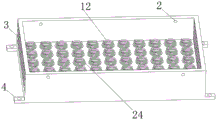
In one embodiment, an elastic member 12 is disposed below the pressure plate 11, and one end of the elastic member 12 is connected to the bottom of the lower case 1 and the other end is connected to the lower surface of the pressure plate 11.
Specifically, the bottom of the lower case 1 is provided with a notch 24, the elastic member 12 is disposed inside the notch 24, the length of the elastic member 12 is greater than the depth of the notch 24, and the diameter of the elastic member 12 is smaller than the diameter of the notch 24.
It should be noted that, the chamber that holds that forms between upper casing 5 and inferior valve 1 sets up elastic component 12 to be located the below of clamp plate 11, make can when the shell overturns, control chip can not appear dropping, and in addition elastic component 12 itself has good shock attenuation effect, can provide powerful cushion effect, thereby plays the effect of protection to the control chip who holds the intracavity. In this embodiment, the elastic member 12 is a spring, one end of the spring is connected to the bottom of the lower case 1, and the other end of the spring is connected to the pressure plate 11.
In one embodiment, the mounting pieces 4 are arranged on one side of the upper shell 5 and one side of the lower shell 1, and the safety protection device is fixed by matching the mounting pieces 4 through bolts.
Referring to fig. 1 to 6, in a second aspect of the present application, there is provided a switching power supply control system including: the protection device comprises an electric energy input detection module, an electric energy output detection module, a switch power supply control module, a switch key module, a heat dissipation module, a driving module, a feedback module and a switch power supply control chip with a protection function, wherein the input end of the switch power supply control module is connected with the output end of the electric energy input detection module, and the output end of the switch power supply control module is connected with the input end of the electric energy output detection module; the input end of the switch power supply control chip is connected with the output end of the electric energy output detection module, and the output end of the switch power supply control chip is connected with the input end of the driving module, the output end of the feedback module and the output end of the switch key module; the output end of the driving module is connected with the input end of the heat dissipation module and the input end of the feedback module.
In one embodiment, a heat dissipation module includes: a controller and peripheral circuit, a pulse width modulation circuit, an output drive circuit, a protection circuit and a fault indication circuit,
the output ends of the controller and the peripheral circuit are connected with the input end of the drive circuit and the input end of the pulse width modulation circuit, and the input ends of the controller and the peripheral circuit are connected with the output end of the protection circuit and the output end of the fault indication circuit; the output end of the output driving circuit is used for being connected with the motor.
It is to be understood that the foregoing examples, while indicating the preferred embodiments of the invention, are given by way of illustration and description, and are not to be construed as limiting the scope of the invention; it should be noted that, for those skilled in the art, the above technical features can be freely combined, and several changes and modifications can be made without departing from the concept of the present invention, which all belong to the protection scope of the present invention; therefore, all equivalent changes and modifications made within the scope of the claims of the present invention should be covered by the claims of the present invention.