CN113884715A - GIS equipment loop resistance test appurtenance - Google Patents

GIS equipment loop resistance test appurtenance Download PDF

Info

Publication number
CN113884715A
CN113884715A CN202111246141.8A CN202111246141A CN113884715A CN 113884715 A CN113884715 A CN 113884715A CN 202111246141 A CN202111246141 A CN 202111246141A CN 113884715 A CN113884715 A CN 113884715A
Authority
CN
China
Prior art keywords
loop resistance
groove
test
component
adjusting
Prior art date
Legal status (The legal status is an assumption and is not a legal conclusion. Google has not performed a legal analysis and makes no representation as to the accuracy of the status listed.)
Granted
Application number
CN202111246141.8A
Other languages
Chinese (zh)
Other versions
CN113884715B (en
Inventor
江峰
刘宇兴
钟明睿
翁卢臻
汪伟群
林群慧
朱经洋
谢政
Current Assignee (The listed assignees may be inaccurate. Google has not performed a legal analysis and makes no representation or warranty as to the accuracy of the list.)
Guangdong Power Grid Co Ltd
Meizhou Power Supply Bureau of Guangdong Power Grid Co Ltd
Original Assignee
Guangdong Power Grid Co Ltd
Meizhou Power Supply Bureau of Guangdong Power Grid Co Ltd
Priority date (The priority date is an assumption and is not a legal conclusion. Google has not performed a legal analysis and makes no representation as to the accuracy of the date listed.)
Filing date
Publication date
Application filed by Guangdong Power Grid Co Ltd, Meizhou Power Supply Bureau of Guangdong Power Grid Co Ltd filed Critical Guangdong Power Grid Co Ltd
Priority to CN202111246141.8A priority Critical patent/CN113884715B/en
Publication of CN113884715A publication Critical patent/CN113884715A/en
Application granted granted Critical
Publication of CN113884715B publication Critical patent/CN113884715B/en
Active legal-status Critical Current
Anticipated expiration legal-status Critical

Links

Images

Classifications

    • G—PHYSICS
    • G01—MEASURING; TESTING
    • G01R—MEASURING ELECTRIC VARIABLES; MEASURING MAGNETIC VARIABLES
    • G01R1/00—Details of instruments or arrangements of the types included in groups G01R5/00 - G01R13/00 and G01R31/00
    • G01R1/02—General constructional details
    • G01R1/04—Housings; Supporting members; Arrangements of terminals
    • G—PHYSICS
    • G01—MEASURING; TESTING
    • G01R—MEASURING ELECTRIC VARIABLES; MEASURING MAGNETIC VARIABLES
    • G01R27/00—Arrangements for measuring resistance, reactance, impedance, or electric characteristics derived therefrom
    • G01R27/02—Measuring real or complex resistance, reactance, impedance, or other two-pole characteristics derived therefrom, e.g. time constant
    • G01R27/08—Measuring resistance by measuring both voltage and current
    • Y—GENERAL TAGGING OF NEW TECHNOLOGICAL DEVELOPMENTS; GENERAL TAGGING OF CROSS-SECTIONAL TECHNOLOGIES SPANNING OVER SEVERAL SECTIONS OF THE IPC; TECHNICAL SUBJECTS COVERED BY FORMER USPC CROSS-REFERENCE ART COLLECTIONS [XRACs] AND DIGESTS
    • Y02—TECHNOLOGIES OR APPLICATIONS FOR MITIGATION OR ADAPTATION AGAINST CLIMATE CHANGE
    • Y02E—REDUCTION OF GREENHOUSE GAS [GHG] EMISSIONS, RELATED TO ENERGY GENERATION, TRANSMISSION OR DISTRIBUTION
    • Y02E10/00—Energy generation through renewable energy sources
    • Y02E10/50—Photovoltaic [PV] energy

Landscapes

  • Physics & Mathematics (AREA)
  • General Physics & Mathematics (AREA)
  • Testing Electric Properties And Detecting Electric Faults (AREA)
  • Measuring Leads Or Probes (AREA)

Abstract

本发明属于电力安全技术领域,公开了一种GIS设备回路电阻测试辅助工具。该GIS设备回路电阻测试辅助工具包括支撑件、测试组件和调节组件,支撑件为圆环结构,支撑件能抵接于接地刀闸的圆盘的底面;测试组件用于连接测试仪器,测试组件包括触头,触头用于与圆盘的端面抵接;支撑件和测试组件通过调节组件连接,调节组件能够沿支撑件的轴向伸缩,以调节触头向圆盘端面施加的抵紧力。本发明提供的GIS设备回路电阻测试辅助工具,通过设置调节组件,调节组件能沿支撑件的轴向伸缩以调节触头向圆盘端面施加的抵紧力,在测试过程中,可根据GIS设备上接地开关的圆盘厚度调节调节组件,以使支撑件和测试组件分别抵到接地刀闸上,提高测试效率和测试可靠性。

Figure 202111246141

The invention belongs to the technical field of electric power safety, and discloses an auxiliary tool for testing loop resistance of GIS equipment. The GIS equipment loop resistance test auxiliary tool includes a support, a test assembly and an adjustment assembly. The support is a ring structure, and the support can abut against the bottom surface of the disc of the grounding switch; the test assembly is used to connect the test instrument and the test assembly. Including a contact, the contact is used for abutting with the end face of the disc; the support and the test assembly are connected by an adjustment assembly, and the adjustment assembly can expand and contract along the axial direction of the support to adjust the contact force exerted by the contact on the end face of the disc . In the auxiliary tool for testing the loop resistance of GIS equipment provided by the present invention, by setting the adjustment component, the adjustment component can expand and contract along the axial direction of the support member to adjust the pressing force exerted by the contact on the end face of the disc. The disc thickness of the upper grounding switch is adjusted and adjusted so that the support piece and the test assembly are respectively abutted on the grounding switch, so as to improve the test efficiency and test reliability.

Figure 202111246141

Description

GIS equipment loop resistance test appurtenance
Technical Field
The invention relates to the technical field of electric power safety, in particular to an auxiliary tool for testing loop resistance of GIS equipment.
Background
GIS (Gas Insulated Switchgear) refers to a Switchgear in which SF6 Gas, N2 Gas, or a mixed Gas at a low pressure is used as an insulating medium of the Switchgear, and vacuum or SF6 is used as an arc extinguishing medium, and medium-voltage elements such as a bus bar, a circuit breaker, and a disconnector are collectively sealed in a case.
In order to ensure the normal operation of the GIS equipment, in the manufacturing, installation, maintenance and operation processes of the GIS equipment, the loop resistance of the conductive part inside the GIS equipment needs to be tested, and whether the defect of poor contact exists inside the GIS equipment is determined through the loop resistance. Because the conductive part of the GIS device is inside the GIS device, the test method adopted in the prior art is generally: closing the circuit breaker or the isolating switch of the part to be measured, closing the grounding switches on two sides of the part to be measured, and removing the grounding connection parts of the grounding switches on two sides; and respectively testing the loop resistances of the grounding switches on the two sides by utilizing the loop resistance test clamp.
When loop resistance measurement is performed on gas insulated switchgear, a test clamp is usually directly adopted to connect a test line on a contact surface of a disc of a grounding switch, and then the test line is connected with a test instrument to measure the loop resistance, however, poor contact or loose fixation often exists between the test clamp and the grounding switch, and the test efficiency is greatly reduced.
Disclosure of Invention
The invention aims to provide an auxiliary tool for testing loop resistance of GIS equipment, which is used for assisting in measuring the loop resistance of the GIS equipment and improving the testing efficiency and the testing reliability.
In order to achieve the purpose, the invention adopts the following technical scheme:
a GIS equipment loop resistance test appurtenance, includes:
the supporting piece is of a circular ring structure and can abut against the bottom surface of the disc of the grounding disconnecting link;
the testing assembly is used for connecting a testing instrument and comprises a contact which is used for abutting against the end face of the disc;
the adjusting assembly is connected with the testing assembly through the supporting piece, and the adjusting assembly can stretch out and draw back along the axial direction of the supporting piece so as to adjust the abutting force applied to the end face of the disc by the contact.
Optionally, the adjusting assembly includes an elastic member, the elastic member extends and retracts along the axial direction of the supporting member, one end of the elastic member is connected with the supporting member, and the other end of the elastic member is connected with the testing assembly.
Optionally, a groove is formed in the supporting piece, a notch of the groove faces the testing assembly, the adjusting assembly further comprises a sliding rod, one end of the sliding rod is connected with a groove wall of the groove in a sliding mode, and the other end of the sliding rod is connected with the testing assembly.
Optionally, the adjusting assembly further includes an extension plate, the extension plate is parallel to the end face of the disc, one end of the extension plate is connected to the testing assembly, and the other end of the extension plate is connected to the sliding rod.
Optionally, the slide bar includes the guide bar and accepts the board, guide bar one end with the test assembly is connected, the other end of guide bar stretch into the recess and with accept the board and be connected, the guide bar with the cell wall interval of recess sets up, accept the board with the cell wall sliding connection of recess.
Optionally, the elastic member includes a first elastic member, the first elastic member is disposed in the groove, one end of the first elastic member abuts against the groove bottom of the groove, and the other end of the first elastic member abuts against the bearing plate;
and/or, the notch of recess is provided with first locating part, the elastic component includes the second elastic component, the second elastic component sets up in the recess, just the one end of second elastic component with accept the board butt, the other end of second elastic component with first locating part butt.
Optionally, the support member includes a vertically connected abutting portion and a mounting portion, the mounting portion extends along an axial direction of the support member, the abutting portion extends along a radial direction of the annular structure and is used for abutting against the bottom surface of the disc, and the adjusting assembly is connected to the mounting portion.
Optionally, GIS equipment loop resistance test appurtenance still includes the casing, the casing is located the outside of test component, the casing with adjusting part is connected, the one end of contact is passed the casing with the terminal surface butt of disc, the other end of contact is used for connecting test instrument.
Optionally, a plurality of adjusting assemblies are arranged on the supporting member at intervals along the circumferential direction, and the adjusting assemblies and the testing assemblies are arranged in one-to-one correspondence;
or, be provided with a plurality of pairs of adjusting part along circumference interval on the support piece, every is every adjusting part all includes along two of support piece's circumference interval sets up adjusting part, adjusting part's logarithm with test component one-to-one, and every test component all with a pair of two in the adjusting part connects.
Optionally, the support is detachably connected with the adjusting assembly;
and/or the adjusting assembly is detachably connected with the testing assembly.
The invention has the beneficial effects that: according to the auxiliary tool for testing the loop resistance of the GIS equipment, the adjusting component is arranged and can stretch out and draw back along the axial direction of the supporting piece so as to adjust the abutting force applied by the contact to the end face of the disc, and in the actual testing process, the adjusting component can be adjusted according to the disc thickness of the grounding switch on the GIS equipment, so that the supporting piece and the testing component are respectively abutted to the grounding switch, the testing component is abutted to the contact surface of the grounding switch, the testing efficiency is improved, and the testing reliability is improved.
Drawings
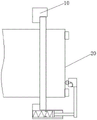
Fig. 1 is a schematic structural diagram of a GIS device loop resistance test auxiliary tool according to an embodiment of the present invention when not in use;
fig. 2 is a front view of the auxiliary tool for testing the loop resistance of the GIS device according to the first embodiment of the present invention, installed on the grounding switch;
fig. 3 is a top view of the GIS device loop resistance test auxiliary tool installed on the grounding switch according to the first embodiment of the present invention;
fig. 4 is a schematic structural diagram of a testing component of the GIS device loop resistance testing auxiliary tool according to the first embodiment of the present invention;
fig. 5 is a schematic structural diagram of a test component of the GIS device loop resistance test auxiliary tool according to the first embodiment of the present invention;
fig. 6 is a schematic structural diagram of a GIS device loop resistance test auxiliary tool according to a second embodiment of the present invention;
fig. 7 is a schematic diagram of a state of the GIS device loop resistance test auxiliary tool according to the second embodiment of the present invention when the auxiliary tool is not in use.
In the figure:
10. auxiliary tools for testing loop resistance of GIS equipment; 20. a grounding disconnecting link;
1. a support member; 11. a groove; 12. a first limit piece; 13. a second limiting member; 2. testing the component; 21. a contact; 22. an interface; 221. a first interface; 222. a second interface; 23. a connecting wire; 3. an adjustment assembly; 31. an elastic member; 311. a first elastic member; 312. a second elastic member; 32. a slide bar; 321. a guide bar; 322. a bearing plate; 33. an extension plate; 4. a housing.
Detailed Description
The present invention will be described in further detail with reference to the accompanying drawings and examples. It is to be understood that the specific embodiments described herein are merely illustrative of the invention and are not limiting of the invention. It should be further noted that, for the convenience of description, only some of the structures related to the present invention are shown in the drawings, not all of the structures.
In the description of the present invention, unless expressly stated or limited otherwise, the terms "connected," "connected," and "fixed" are to be construed broadly, e.g., as meaning permanently connected, removably connected, or integral to one another; can be mechanically or electrically connected; either directly or indirectly through intervening media, either internally or in any other relationship. The specific meanings of the above terms in the present invention can be understood in specific cases to those skilled in the art.
In the present invention, unless otherwise expressly stated or limited, "above" or "below" a first feature means that the first and second features are in direct contact, or that the first and second features are not in direct contact but are in contact with each other via another feature therebetween. Also, the first feature being "on," "above" and "over" the second feature includes the first feature being directly on and obliquely above the second feature, or merely indicating that the first feature is at a higher level than the second feature. A first feature being "under," "below," and "beneath" a second feature includes the first feature being directly under and obliquely below the second feature, or simply meaning that the first feature is at a lesser elevation than the second feature.
In the description of the present embodiment, the terms "upper", "lower", "right", etc. are used in an orientation or positional relationship based on that shown in the drawings only for convenience of description and simplicity of operation, and do not indicate or imply that the device or element referred to must have a particular orientation, be constructed and operated in a particular orientation, and thus, should not be construed as limiting the present invention. Furthermore, the terms "first" and "second" are used only for descriptive purposes and are not intended to have a special meaning.
Example one
The embodiment provides an auxiliary tool for testing the resistance of a GIS (geographic information system) equipment loop, as shown in fig. 1-3, the auxiliary tool for testing the resistance of the GIS equipment loop comprises a supporting piece 1, a testing component 2 and an adjusting component 3, wherein the supporting piece 1 is of a circular ring structure, and the supporting piece 1 can be abutted against the bottom surface of a disc of a grounding disconnecting link 20; the testing component 2 is used for connecting a testing instrument, the testing component 2 comprises a contact 21, and the contact 21 is used for being abutted against the end face of the disc; the supporting part 1 and the testing component 2 are connected through the adjusting component 3, and the adjusting component 3 can stretch and retract along the axial direction of the supporting part 1 so as to adjust the abutting force applied by the contact 21 to the end face of the disc.
According to the auxiliary tool for testing the loop resistance of the GIS equipment, provided by the invention, the adjusting component 3 is arranged, the adjusting component 3 can stretch and retract along the axial direction of the supporting piece 1 to adjust the abutting force applied by the contact 21 to the end face of the disc, and in the actual testing process, the adjusting component 3 can be adjusted according to the disc thickness of the grounding switch on the GIS equipment, so that the supporting piece 1 and the testing component 2 are respectively abutted against the grounding switch 20, the testing component 2 is abutted against the contact surface of the grounding switch 20, the testing efficiency and the testing reliability are improved, and meanwhile, the auxiliary tool for testing can be suitable for testing discs with different thicknesses.
Optionally, the adjusting assembly 3 includes an elastic member 31, the elastic member 31 extends and contracts along the axial direction of the supporting member 1, one end of the elastic member 31 is connected with the supporting member 1, and the other end of the elastic member 31 is connected with the testing assembly 2. By arranging the elastic member 31, the elastic member 31 can be conveniently axially extended and retracted, and the abutting force of the contact 21 to the end face of the disc can be adjusted.
In order to improve the stability of the axial movement of the elastic member 31, the supporting member 1 is provided with a groove 11, the notch of the groove 11 faces the testing component 2, the adjusting component 3 further comprises a sliding rod 32, one end of the sliding rod 32 is slidably connected with the groove wall of the groove 11, and the other end of the sliding rod 32 is connected with the testing component 2. By providing the slide rod 32, the slide rod 32 can improve the directionality of the movement of the elastic member 31 in the axial direction of the support member 1.
Optionally, the adjusting assembly 3 further comprises an extending plate 33, the extending plate 33 is disposed parallel to the end face of the disk, one end of the extending plate 33 is connected to the testing assembly 2, and the other end of the extending plate 33 is connected to the elastic member 31 or the sliding rod 32. By arranging the extension plate 33, the extension plate 33 is arranged in parallel with the end face of the disc, and the extension plate 33 enables the contact 21 to be abutted close to the center of the end face of the disc, so that the abutting reliability and stability are improved.
In order to improve the guiding stability of the sliding rod 32, the sliding rod 32 includes a guiding rod 321 and a bearing plate 322, one end of the guiding rod 321 is connected with the extending plate 33, the other end of the guiding rod 321 extends into the groove 11 and is connected with the bearing plate 322, the guiding rod 321 is spaced from the groove wall of the groove 11, and the bearing plate 322 is slidably connected with the groove wall of the groove 11. By the arrangement, the sliding stability can be ensured, and meanwhile, the contact area between the sliding rod 32 and the groove wall of the groove 11 is reduced, and the friction is reduced.
Optionally, a first stopper 12 is disposed at the notch of the groove 11. When the bearing plate 322 moves to the notch of the groove 11, the first limiting member 12 can effectively prevent the bearing plate 322 from separating from the notch, thereby improving the reliability of the adjusting assembly 3.
Further, the elastic member 31 includes a first elastic member 311, the first elastic member 311 is disposed in the groove 11, one end of the first elastic member 311 abuts against the groove bottom of the groove 11, and the other end of the first elastic member 311 abuts against the receiving plate 322. In the actual test process, the supporting member 1 abuts against the bottom surface of the disc, the contact 21 abuts against the end surface of the disc, the first elastic member 311 is in a stretching state, and the first elastic member 311 can provide a pulling force for the bearing plate 322, so that the abutting force applied by the contact 21 to the cross section of the disc is adjusted. In addition, the first elastic member 311 is accommodated in the groove 11, so that the first elastic member 311 can be prevented from shaking, and the movement stability of the first elastic member 311 is improved. Optionally, the first elastic member 311 is a spring, which simplifies the structure and reduces the cost. In other embodiments, a person skilled in the art can set the specific structure of the first elastic member 311 according to the specific application scenario.
In order to prevent the receiving plate 322 from pressing the first elastic member 311 to lower the reliability of the first elastic member 311, a second stopper 13 is disposed on a wall of the recess 11. Preferably, the distance from the second limiting member 13 to the bottom of the groove 11 is equal to the length of the first elastic member 311 in the relaxed state. With this arrangement, the reliability of the first elastic member 311 can be ensured to the maximum.
Optionally, the supporting member 1 includes a vertically connected abutting portion and a mounting portion, the mounting portion extends along an axial direction of the supporting member 1, the abutting portion extends along a radial direction of the annular structure and is used for abutting against a bottom surface of the disk, and the adjusting assembly 3 is connected to the mounting portion. In the actual production process, the supporting piece 1 is arranged into the abutting part and the mounting part which are vertically connected, the structure is simple, and the manufacturing is easy. Secondly, the abutting portion extends in the radial direction of the annular structure and is used for abutting against the bottom surface of the disk, and the abutting stability can be improved.
In the actual manufacturing process, a plurality of adjusting assemblies 3 are arranged on the supporting piece 1 at intervals along the circumferential direction, and the adjusting assemblies 3 and the testing assemblies 2 are arranged in a one-to-one correspondence manner; or, be provided with a plurality of pairs of adjusting part 3 along circumference interval on support piece 1, every adjusting part 3 all includes two adjusting part 3 along support piece 1's circumference interval setting, adjusting part 3's logarithm and test component 2 one-to-one, and every test component 2 all with two in a pair of adjusting part 3 is connected. Through setting up a plurality of adjusting part 3 or a plurality of adjusting part 3, the distance between regulation support piece 1 that can be better and the test component 2 improves the stability of the 2 atress of test component, and then improves the reliability and the accuracy of test.
Optionally, the support 1 is detachably connected with the adjustment assembly 3; and/or the adjusting assembly 3 is detachably connected with the testing assembly 2. The arrangement is convenient to install and disassemble.
Optionally, the auxiliary tool for testing the loop resistance of the GIS equipment further comprises a housing 4, the housing 4 is arranged on the outer side of the testing component 2, the housing 4 is connected with the adjusting component 3, one end of the contact 21 penetrates through the housing 4 to abut against the end face of the disc, and the other end of the contact 21 is used for connecting a testing instrument. Through setting up casing 4, casing 4 locates the outside of test assembly 2, has improved the security and the reliability of test assembly 2.
As shown in fig. 4 and 5, the testing assembly 2 further includes an interface 22 and a connection line 23, the interface 22 is connected to the contact 21 through the connection line 23, the connection line 23 is located inside the housing 4, the interface 22 is disposed outside the housing 4, and the interface 22 is used for connecting a testing instrument. By providing the connection line 23 inside the housing 4, the safety of the test assembly 2 is improved. Optionally, the connection line 23 is a annealed copper line. In other embodiments, the material of the connection line 23 can be set by those skilled in the art according to the specific application.
In actual use, the interface 22 includes a first interface 221 and a second interface 222, the first interface 221 is used for connecting with a current test line, and the second interface 222 is used for connecting with a voltage test line. During testing, the two auxiliary tools for testing the loop resistance of the GIS equipment are respectively abutted against the grounding disconnecting link 20, the respective first interface 221 is respectively connected with the current testing line, the respective second interface 222 is connected with the voltage testing line, and the loop resistance of the GIS equipment can be obtained through a testing instrument.
Example two
The present embodiment provides an auxiliary tool for testing a resistance of a GIS device loop, and a basic structure of the auxiliary tool for testing a resistance of a GIS device loop provided by the present embodiment is the same as that of the first embodiment, and only a part of the structure is different. The present embodiment will be described only with respect to a structure different from the first embodiment.
As shown in fig. 6 and 7, in the present embodiment, the elastic member 31 includes not only the first elastic member 311, but also the second elastic member 312, the second elastic member 312 is disposed in the recess 11, one end of the second elastic member 312 abuts against the receiving plate 322, and the other end of the second elastic member 312 abuts against the first limiting member 12. When using GIS equipment loop resistance test appurtenance, second elastic component 312 is in compression state, first elastic component 311 is in tensile state, second elastic component 312 and first elastic component 311 all can provide the thrust of accepting board 322 towards support piece 1, can be on the basis of reducing the elastic coefficient of first elastic component 311 and second elastic component 312, make test assembly 2 butt on the terminal surface of ground connection knife-switch 20 disc better, improved GIS equipment loop resistance test appurtenance's test accuracy.
It is understood that in other embodiments, the elastic member 31 may only include the second elastic member 312, and the first elastic member 311 is not required, and the contact 21 is provided with a force against the end face of the disk by the compression of the second elastic member 312 during the test.
It should be understood that the above-described embodiments of the present invention are merely examples for clearly illustrating the present invention, and are not intended to limit the embodiments of the present invention. Numerous obvious variations, adaptations and substitutions will occur to those skilled in the art without departing from the scope of the invention. And are neither required nor exhaustive of all embodiments. Any modification, equivalent replacement, and improvement made within the spirit and principle of the present invention should be included in the protection scope of the claims of the present invention.

Claims (10)

1. The utility model provides a GIS equipment loop resistance test appurtenance which characterized in that includes:
the supporting piece (1) is of a circular ring structure, and the supporting piece (1) can abut against the bottom surface of a disc of the grounding disconnecting link (20);
the testing assembly (2) is used for connecting a testing instrument, the testing assembly (2) comprises a contact (21), and the contact (21) is used for being abutted with the end face of the disc;
the adjusting assembly (3), the support piece (1) with the test assembly (2) pass through the adjusting assembly (3) is connected, the adjusting assembly (3) can stretch out and draw back along the axial of support piece (1) to adjust the contact (21) to the abutting force that the terminal surface of disc applyed.
2. The GIS device loop resistance test auxiliary tool according to claim 1, wherein the adjusting component (3) comprises an elastic member (31), the elastic member (31) extends and retracts along the axial direction of the supporting member (1), one end of the elastic member (31) is connected with the supporting member (1), and the other end of the elastic member (31) is connected with the test component (2).
3. The GIS device loop resistance test auxiliary tool according to claim 2, wherein the supporting member (1) is provided with a groove (11), the notch of the groove (11) faces the test component (2), the adjusting component (3) further comprises a sliding rod (32), one end of the sliding rod (32) is slidably connected with the groove wall of the groove (11), and the other end of the sliding rod (32) is connected with the test component (2).
4. The GIS device loop resistance test auxiliary tool according to claim 3, characterized in that the adjusting component (3) further comprises an extension plate (33), the extension plate (33) is arranged in parallel with the end surface of the disk, one end of the extension plate (33) is connected with the testing component (2), and the other end of the extension plate (33) is connected with the sliding rod (32).
5. The GIS device loop resistance test auxiliary tool according to claim 3, wherein the sliding rod (32) comprises a guiding rod (321) and a bearing plate (322), one end of the guiding rod (321) is connected with the test component (2), the other end of the guiding rod (321) extends into the groove (11) and is connected with the bearing plate (322), the guiding rod (321) is arranged at a distance from the groove wall of the groove (11), and the bearing plate (322) is connected with the groove wall of the groove (11) in a sliding manner.
6. The GIS device loop resistance test auxiliary tool according to claim 5, wherein the elastic member (31) comprises a first elastic member (311), the first elastic member (311) is arranged in the groove (11), one end of the first elastic member (311) abuts against the groove bottom of the groove (11), and the other end of the first elastic member (311) abuts against the bearing plate (322);
and/or a first limiting piece (12) is arranged on a notch of the groove (11), the elastic piece (31) comprises a second elastic piece (312), the second elastic piece (312) is arranged in the groove (11), one end of the second elastic piece (312) is abutted to the bearing plate (322), and the other end of the second elastic piece (312) is abutted to the first limiting piece (12).
7. The GIS device loop resistance test auxiliary tool according to any one of claims 1-6, wherein the support member (1) comprises a vertically connected abutting portion and a mounting portion, the mounting portion extends along the axial direction of the support member (1), the abutting portion extends along the radial direction of the ring structure and is used for abutting against the bottom surface of the disk, and the adjusting assembly (3) is connected to the mounting portion.
8. The GIS device loop resistance test auxiliary tool according to any one of claims 1 to 6, wherein the GIS device loop resistance test auxiliary tool further comprises a housing (4), the housing (4) is arranged on the outer side of the test component (2), the housing (4) is connected with the adjusting component (3), one end of the contact (21) penetrates through the housing (4) to abut against the end face of the disc, and the other end of the contact (21) is used for connecting a test instrument.
9. The GIS equipment loop resistance test auxiliary tool according to any one of claims 1-6, characterized in that a plurality of the adjusting components (3) are arranged on the supporting member (1) at intervals along the circumferential direction, and the adjusting components (3) are arranged in one-to-one correspondence with the testing components (2);
or, support piece (1) is gone up and is provided with a plurality of pairs of adjusting part (3) along circumference interval, and every is every adjusting part (3) all include along two of the circumference interval setting of support piece (1) adjusting part (3), the logarithm of adjusting part (3) with test component (2) one-to-one, and every test component (2) all with a pair two in adjusting part (3) are connected.
10. The GIS device loop resistance test aid according to any of claims 1-6, characterized in that the support (1) is detachably connected with the adjusting assembly (3);
and/or the adjusting component (3) is detachably connected with the testing component (2).
CN202111246141.8A 2021-10-26 2021-10-26 An Auxiliary Tool for GIS Equipment Loop Resistance Test Active CN113884715B (en)

Priority Applications (1)

Application Number Priority Date Filing Date Title
CN202111246141.8A CN113884715B (en) 2021-10-26 2021-10-26 An Auxiliary Tool for GIS Equipment Loop Resistance Test

Applications Claiming Priority (1)

Application Number Priority Date Filing Date Title
CN202111246141.8A CN113884715B (en) 2021-10-26 2021-10-26 An Auxiliary Tool for GIS Equipment Loop Resistance Test

Publications (2)

Publication Number Publication Date
CN113884715A true CN113884715A (en) 2022-01-04
CN113884715B CN113884715B (en) 2023-07-21

Family

ID=79014352

Family Applications (1)

Application Number Title Priority Date Filing Date
CN202111246141.8A Active CN113884715B (en) 2021-10-26 2021-10-26 An Auxiliary Tool for GIS Equipment Loop Resistance Test

Country Status (1)

Country Link
CN (1) CN113884715B (en)

Cited By (1)

* Cited by examiner, † Cited by third party
Publication number Priority date Publication date Assignee Title
CN114460337A (en) * 2022-02-10 2022-05-10 广东电网有限责任公司 Protection device of resistance tester

Citations (11)

* Cited by examiner, † Cited by third party
Publication number Priority date Publication date Assignee Title
DE716616C (en) * 1936-05-07 1942-01-24 Telefunken Gmbh Circuit arrangement for setting the amplitude and phase of an alternating voltage
GB0207353D0 (en) * 2001-03-30 2002-05-08 Welch Iain E Electrical circuit testing aid
JP2006250620A (en) * 2005-03-09 2006-09-21 Omron Corp Contact probe, inspection device and coil product inspection device
JP2015159079A (en) * 2014-02-25 2015-09-03 中国電力株式会社 Connecting instrument and terminal connecting method
CN205426957U (en) * 2016-03-24 2016-08-03 国网天津市电力公司 Switch equipment loop resistance subtest pole
CN205426970U (en) * 2016-03-24 2016-08-03 国网天津市电力公司 Switch equipment loop resistance subtest presss from both sides
CN108051616A (en) * 2017-10-23 2018-05-18 国网辽宁省电力有限公司本溪供电公司 GIS device loop resistance tests auxiliary tool and power construction implementation
CN209264783U (en) * 2018-12-11 2019-08-16 云南电网有限责任公司楚雄供电局 A kind of Telescopic Fixed device and monitor station
CN210863824U (en) * 2019-10-16 2020-06-26 云南电力技术有限责任公司 Auxiliary device for loop resistance test of GIS (gas insulated switchgear)
CN211955716U (en) * 2020-03-27 2020-11-17 陕西中兴祥林电子科技有限公司 A UHF partial discharge detection device suitable for GIS equipment
CN212207510U (en) * 2020-04-20 2020-12-22 常州翊迈新材料科技有限公司 General type tester of contact resistance

Patent Citations (11)

* Cited by examiner, † Cited by third party
Publication number Priority date Publication date Assignee Title
DE716616C (en) * 1936-05-07 1942-01-24 Telefunken Gmbh Circuit arrangement for setting the amplitude and phase of an alternating voltage
GB0207353D0 (en) * 2001-03-30 2002-05-08 Welch Iain E Electrical circuit testing aid
JP2006250620A (en) * 2005-03-09 2006-09-21 Omron Corp Contact probe, inspection device and coil product inspection device
JP2015159079A (en) * 2014-02-25 2015-09-03 中国電力株式会社 Connecting instrument and terminal connecting method
CN205426957U (en) * 2016-03-24 2016-08-03 国网天津市电力公司 Switch equipment loop resistance subtest pole
CN205426970U (en) * 2016-03-24 2016-08-03 国网天津市电力公司 Switch equipment loop resistance subtest presss from both sides
CN108051616A (en) * 2017-10-23 2018-05-18 国网辽宁省电力有限公司本溪供电公司 GIS device loop resistance tests auxiliary tool and power construction implementation
CN209264783U (en) * 2018-12-11 2019-08-16 云南电网有限责任公司楚雄供电局 A kind of Telescopic Fixed device and monitor station
CN210863824U (en) * 2019-10-16 2020-06-26 云南电力技术有限责任公司 Auxiliary device for loop resistance test of GIS (gas insulated switchgear)
CN211955716U (en) * 2020-03-27 2020-11-17 陕西中兴祥林电子科技有限公司 A UHF partial discharge detection device suitable for GIS equipment
CN212207510U (en) * 2020-04-20 2020-12-22 常州翊迈新材料科技有限公司 General type tester of contact resistance

Non-Patent Citations (2)

* Cited by examiner, † Cited by third party
Title
郭小燕: "GW5型隔离开关调整要点解析", 河北工业科技, vol. 30, no. 6, pages 453 - 456 *
高晓东: "10KV真空断路器在铁路自闭供电系统中的使用和检测", 上海铁道科技, no. 2, pages 37 - 39 *

Cited By (2)

* Cited by examiner, † Cited by third party
Publication number Priority date Publication date Assignee Title
CN114460337A (en) * 2022-02-10 2022-05-10 广东电网有限责任公司 Protection device of resistance tester
CN114460337B (en) * 2022-02-10 2024-11-08 广东电网有限责任公司 A protection device for a resistance tester

Also Published As

Publication number Publication date
CN113884715B (en) 2023-07-21

Similar Documents

Publication Publication Date Title
CN105510780B (en) SF6 High-Voltage Electrical Appliances insulated pull rod Insulation Test system and method
CN102735968B (en) GIS (Geographic Information System) fault diagnosis system and method based on vibration signal spectrum analysis
CN103353574B (en) A kind of insulation test device of GIS insulated tension pole
CN109444486B (en) Test clamp and circuit resistance test device for central cabinet circuit breaker
CN107843820A (en) A kind of insulator arc-over warning device
CN202735426U (en) GIS fault diagnosis system based on vibration signal spectral analysis
CN104049115A (en) Polymer soft package battery detecting clamp
Liu et al. Research of mechanical state diagnosis techniques in GIS bus connector based on mechanical vibration
CN201159680Y (en) A special bracket for quality inspection of high-voltage vacuum circuit breaker interrupter chamber
CN113884715B (en) An Auxiliary Tool for GIS Equipment Loop Resistance Test
CN207689622U (en) A kind of insulator arc-over warning device
CN210863824U (en) Auxiliary device for loop resistance test of GIS (gas insulated switchgear)
CN203849295U (en) Pneumatic fixture of moulded case circuit breaker
CN211654754U (en) High voltage current limiting fuse
CN104848979A (en) A high-voltage switchgear plum blossom contact insertion force detection device and its test method
CN211651819U (en) A GIS busbar vibration monitoring device
CN222867349U (en) A lightning arrester with breaking function
CN106918779B (en) High-voltage circuit breaker closing resistance heat capacity test device
CN202886560U (en) Field detecting system for gas insulated switch mechanical faults
CN117054831A (en) A multifunctional platform for electrical performance testing of insulating materials
CN110068753A (en) GIS detecting device for basin type insulator and method based on case vibration signal
CN108693389A (en) A frame type circuit breaker withstand voltage test fixture
CN223796629U (en) Totally-enclosed insulating transformer and field unified test fixture
CN223679338U (en) Multifunctional electroscope test frame
CN113851865B (en) Omega type universal wire clamp

Legal Events

Date Code Title Description
PB01 Publication
PB01 Publication
SE01 Entry into force of request for substantive examination
GR01 Patent grant
GR01 Patent grant