CN113883121A - Hydraulic oil cylinder - Google Patents
Hydraulic oil cylinder Download PDFInfo
- Publication number
- CN113883121A CN113883121A CN202111051584.1A CN202111051584A CN113883121A CN 113883121 A CN113883121 A CN 113883121A CN 202111051584 A CN202111051584 A CN 202111051584A CN 113883121 A CN113883121 A CN 113883121A
- Authority
- CN
- China
- Prior art keywords
- hydraulic cylinder
- movable cavity
- cylinder body
- piston
- close
- Prior art date
- Legal status (The legal status is an assumption and is not a legal conclusion. Google has not performed a legal analysis and makes no representation as to the accuracy of the status listed.)
- Pending
Links
- 239000010720 hydraulic oil Substances 0.000 title claims description 38
- 239000003921 oil Substances 0.000 claims abstract description 85
- 238000004321 preservation Methods 0.000 claims abstract description 37
- 230000000149 penetrating effect Effects 0.000 claims abstract description 18
- 230000007246 mechanism Effects 0.000 claims description 43
- 238000007789 sealing Methods 0.000 claims description 28
- 230000000295 complement effect Effects 0.000 claims description 2
- 230000033001 locomotion Effects 0.000 abstract description 21
- 238000000034 method Methods 0.000 abstract description 19
- 230000008569 process Effects 0.000 abstract description 19
- 239000010687 lubricating oil Substances 0.000 abstract description 5
- 238000005057 refrigeration Methods 0.000 abstract description 5
- 230000003245 working effect Effects 0.000 description 6
- 230000000694 effects Effects 0.000 description 5
- 239000012530 fluid Substances 0.000 description 5
- 238000005299 abrasion Methods 0.000 description 4
- 230000000630 rising effect Effects 0.000 description 4
- 230000008859 change Effects 0.000 description 3
- 239000004519 grease Substances 0.000 description 3
- 230000007774 longterm Effects 0.000 description 3
- 238000012423 maintenance Methods 0.000 description 3
- 238000001816 cooling Methods 0.000 description 2
- 239000007788 liquid Substances 0.000 description 2
- 230000004075 alteration Effects 0.000 description 1
- 230000009286 beneficial effect Effects 0.000 description 1
- 230000005540 biological transmission Effects 0.000 description 1
- 239000003638 chemical reducing agent Substances 0.000 description 1
- 230000005494 condensation Effects 0.000 description 1
- 238000009833 condensation Methods 0.000 description 1
- 238000002347 injection Methods 0.000 description 1
- 239000007924 injection Substances 0.000 description 1
- 230000001050 lubricating effect Effects 0.000 description 1
- 238000012986 modification Methods 0.000 description 1
- 230000004048 modification Effects 0.000 description 1
- 230000003647 oxidation Effects 0.000 description 1
- 238000007254 oxidation reaction Methods 0.000 description 1
- 230000002035 prolonged effect Effects 0.000 description 1
- 239000000243 solution Substances 0.000 description 1
- 238000006467 substitution reaction Methods 0.000 description 1
Images




Classifications
-
- F—MECHANICAL ENGINEERING; LIGHTING; HEATING; WEAPONS; BLASTING
- F15—FLUID-PRESSURE ACTUATORS; HYDRAULICS OR PNEUMATICS IN GENERAL
- F15B—SYSTEMS ACTING BY MEANS OF FLUIDS IN GENERAL; FLUID-PRESSURE ACTUATORS, e.g. SERVOMOTORS; DETAILS OF FLUID-PRESSURE SYSTEMS, NOT OTHERWISE PROVIDED FOR
- F15B15/00—Fluid-actuated devices for displacing a member from one position to another; Gearing associated therewith
- F15B15/08—Characterised by the construction of the motor unit
- F15B15/14—Characterised by the construction of the motor unit of the straight-cylinder type
- F15B15/1423—Component parts; Constructional details
- F15B15/1428—Cylinders
-
- F—MECHANICAL ENGINEERING; LIGHTING; HEATING; WEAPONS; BLASTING
- F15—FLUID-PRESSURE ACTUATORS; HYDRAULICS OR PNEUMATICS IN GENERAL
- F15B—SYSTEMS ACTING BY MEANS OF FLUIDS IN GENERAL; FLUID-PRESSURE ACTUATORS, e.g. SERVOMOTORS; DETAILS OF FLUID-PRESSURE SYSTEMS, NOT OTHERWISE PROVIDED FOR
- F15B15/00—Fluid-actuated devices for displacing a member from one position to another; Gearing associated therewith
- F15B15/08—Characterised by the construction of the motor unit
- F15B15/14—Characterised by the construction of the motor unit of the straight-cylinder type
- F15B15/1423—Component parts; Constructional details
- F15B15/1471—Guiding means other than in the end cap
-
- F—MECHANICAL ENGINEERING; LIGHTING; HEATING; WEAPONS; BLASTING
- F15—FLUID-PRESSURE ACTUATORS; HYDRAULICS OR PNEUMATICS IN GENERAL
- F15B—SYSTEMS ACTING BY MEANS OF FLUIDS IN GENERAL; FLUID-PRESSURE ACTUATORS, e.g. SERVOMOTORS; DETAILS OF FLUID-PRESSURE SYSTEMS, NOT OTHERWISE PROVIDED FOR
- F15B2215/00—Fluid-actuated devices for displacing a member from one position to another
- F15B2215/30—Constructional details thereof
Landscapes
- Engineering & Computer Science (AREA)
- Physics & Mathematics (AREA)
- Fluid Mechanics (AREA)
- Mechanical Engineering (AREA)
- General Engineering & Computer Science (AREA)
- Actuator (AREA)
Abstract
The invention relates to the technical field of hydraulic cylinders, in particular to a hydraulic cylinder which comprises a hydraulic cylinder body, wherein a first oil inlet and outlet is arranged on the right outer surface of the hydraulic cylinder body in a penetrating manner and is close to the edge of the upper end, and a left outer surface of the hydraulic cylinder body is provided with a first oil inlet and outlet. According to the invention, by arranging the first movable cavity, when the hydraulic cylinder body works, the piston rod compresses air in the first movable cavity in the process of moving towards the top in the hydraulic cylinder body to form compressed air, the compressed air enters the nozzle on the converter body from the air outlet to finally obtain cold air flow required by refrigeration, meanwhile, the air flow on the outer layer part obtains momentum, the cold air flow enters the heat preservation cavity through the second connecting pipe to cool the hydraulic cylinder body, and after the oil temperature is increased and the viscosity is reduced, a lubricating oil film between the relative motion surfaces of the hydraulic piston and the hydraulic rod is thinned, the service life of the oil and the normal work of the hydraulic cylinder body are ensured, and the practicability and the universality of the whole are improved.
Description
Technical Field
The invention relates to the technical field of hydraulic oil cylinders, in particular to a hydraulic oil cylinder.
Background
The hydraulic cylinder is a hydraulic actuating element which converts hydraulic energy into mechanical energy and does linear reciprocating motion, has simple structure and reliable work, can omit a speed reducer when the hydraulic cylinder is used for realizing reciprocating motion, has no transmission clearance and moves stably, thereby being widely applied to hydraulic systems of various machines, and the output force of the hydraulic cylinder is in direct proportion to the effective area of a piston and the pressure difference between the two sides of the piston.
Chinese patent discloses a hydraulic oil cylinder with the patent application number of CN201810633596.7, which comprises a cylinder body, a piston rod and a piston, the limiting plate, sealing module, clearance module and oiling mouth, the piston rod lower extreme is located the cylinder body, the piston rod upper end is located outside the cylinder body, the piston passes through the piston rod lower extreme and installs in the cylinder body, the piston outward flange is inseparable with the contact of cylinder body inner wall, the piston is used for driving the piston rod and reciprocates, the limiting plate passes through the piston rod and installs in the cylinder body, the limiting plate is located the piston top, the limiting plate is used for limiting the length that the piston rod stretches out the cylinder body, sealing module is located the cylinder body upper cover plate, sealing module is used for sealing up the cylinder body, clearance module passes through the piston rod and fixes inside the cylinder body, clearance module is used for clearing up remaining hydraulic oil on the cylinder body inner wall, the oiling mouth is located cylinder body lower floor, the oiling mouth is used for the injected hydraulic oil to cylinder body internal injection.
Although above-mentioned contrast patent can prolong hydraulic cylinder's life, the frequency of hydraulic cylinder maintenance has been reduced, but when the pneumatic cylinder was in the higher operational environment of temperature ratio, the oil temperature risees and can make the viscosity of oil reduce, make fluid pass through the flow increase of orifice of throttling or slit formula valve, make the operating speed that originally adjusts change, influence the stability of work, reduce the work precision, simultaneously the oil temperature risees the viscosity and reduces the back, the lubricating film between hydraulic piston and the hydraulic stem relative motion surface will become the attenuation, can increase mechanical wear like this, break down easily when fluid is not too clean, the oil temperature risees the oxidation that makes fluid and accelerates, lead to fluid rotten, reduce the life of oil, influence the normal work of system.
To this end, a hydraulic cylinder is proposed.
Disclosure of Invention
The present invention is directed to a hydraulic cylinder to solve the above problems of the prior art.
In order to achieve the purpose, the invention provides the following technical scheme: a hydraulic cylinder comprises a hydraulic cylinder body, wherein a first oil inlet and outlet is formed in the position, close to the upper end edge, of the outer surface of the right side of the hydraulic cylinder body in a penetrating mode, a second oil inlet and outlet is formed in the position, close to the lower end edge, of the outer surface of the left side of the hydraulic cylinder body in a penetrating mode, a piston rod is arranged in the middle of the outer surface of the lower end of the hydraulic cylinder body in a penetrating mode, a guide sleeve is fixedly installed on the position, close to the lower end edge, of the outer surface of the piston rod, the guide sleeve is located inside the hydraulic cylinder body, a first piston body is fixedly installed on the position, close to the upper end, of the outer surface of the piston rod, and a protection mechanism is arranged on the outer surface of the left side of the hydraulic cylinder body;
the protection mechanism comprises a first movable cavity, a second piston body, a first connecting pipe, a first connecting rod, a first limiting block, an air outlet, a converter body, a nozzle, a cold end pipe, a hot end pipe, a vortex chamber, a first control valve, a second connecting pipe, a heat preservation cavity and an auxiliary mechanism, wherein the second piston body is movably connected inside the first movable cavity, the inner surface of the left side of the first movable cavity is close to the edge of the lower end of the first movable cavity and is in through connection with the first connecting pipe, one end of the first connecting pipe, far away from the first movable cavity, is in through connection with a second oil inlet and outlet, the first connecting rod is fixedly connected in the middle of the outer surface of the lower end of the second piston body, penetrates through the outer surface of the lower end of the first movable cavity and is fixedly connected with the piston rod, and the first limiting block is fixedly installed inside the first movable cavity, close to the upper end of the first connecting pipe, the first limiting block is positioned at the lower end of the second piston body, the middle position of the inner surface of the upper end of the first movable cavity is provided with an air outlet in a penetrating way, the upper end of the outer surface of the hydraulic cylinder body, which is close to the air outlet, is surrounded by the converter body, the position of the outer surface of the lower end of the converter body, which corresponds to the air outlet, is provided with a nozzle in a penetrating way, the left side of the inside of the converter body, which is close to the nozzle, is provided with a cold end pipe, the right side of the inside of the converter body is provided with a hot end pipe, the upper end of the inside of the converter body, which is close to the nozzle, is provided with a vortex chamber, the edge position of one end of the inside of the converter body, which is close to the cold end pipe, is provided with a first control valve, the edge position of one end of the inside of the converter body, which is close to the hot end pipe, is provided with a second control valve, one end of the cold end pipe, is connected with a second connecting pipe in a threaded way, and the outer surface of the hydraulic cylinder body is provided with a heat preservation cavity, the heat preservation chamber is located between converter body and the pneumatic cylinder body, the other end and the heat preservation chamber threaded connection of second connecting pipe, the right side surface of pneumatic cylinder body sets up complementary unit.
Although the above mentioned patent can prolong the service life of the hydraulic cylinder and reduce the maintenance frequency of the hydraulic cylinder, when the hydraulic cylinder is in a working environment with higher temperature, the oil temperature is increased to reduce the viscosity of the oil, so that the flow of the oil passing through the orifice or the slit valve is increased, and the originally adjusted working speed is changed, which affects the stability of the work, by providing the first movable cavity, when the hydraulic cylinder body works, the piston rod moves towards the top direction in the hydraulic cylinder body, because the first connecting rod is fixedly connected with the piston rod, the first connecting rod moves upwards in the first movable cavity, for the hydraulic cylinder body which frequently reciprocates, the piston rod moves towards the top direction in the hydraulic cylinder body very fast, and the first connecting rod moves upwards in the first movable cavity very fast, because the second piston body is in sealed movable connection with the first movable cavity, in the process that the first connecting rod moves upwards, air in the first movable cavity is compressed to form compressed air, the compressed air enters the nozzle on the converter body from the air outlet, enters the nozzle at the moment, expands and accelerates in the nozzle and is jetted into the vortex chamber from the tangential direction to form free vortex, the rotating angular velocity of the free vortex is larger as the rotating angular velocity is closer to the center, friction is generated between layers of the free vortex due to different angular velocities, the airflow angular velocity of the central part is the largest, the friction results are that energy is transferred to the airflow with lower angular velocity on the outer layer, the airflow of the central layer part loses energy, the kinetic energy is low, the velocity is reduced, the temperature is reduced, the airflow is led out from the cold end pipe of the converter body through the first control valve to obtain cold airflow required by refrigeration, and meanwhile, the airflow of the outer layer part obtains momentum, the kinetic energy is increased, the kinetic energy is rubbed with the inner wall of the converter body to convert partial kinetic energy into heat energy, the heat energy is led out from a hot end pipe of the converter body through a second control valve to form hot air flow, the flow and the temperature of the cold air flow and the hot air flow can be adjusted by controlling a first control valve and a second control valve, cold air flow enters a heat preservation cavity through a second connecting pipe to cool the hydraulic cylinder body, the viscosity of oil is prevented from being reduced due to the rise of the oil temperature in a high-temperature working environment, the flow of the oil passing through a throttling small hole or a slit valve is increased, the originally adjusted working speed is changed, the working stability and the working precision of the hydraulic cylinder are ensured, a lubricating oil film between the relative motion surfaces of a hydraulic piston and a hydraulic rod is thinned after the oil temperature is prevented from rising and being reduced, the mechanical abrasion is reduced, and the service life of the oil and the normal work of the hydraulic cylinder body are ensured, the practicability and the universality of the whole body are improved.
Preferably, one end of the hot end pipe close to the second control valve is in threaded connection with a third connecting pipe, and the other end of the third connecting pipe is in threaded connection with the heat preservation cavity.
When the hydraulic cylinder body needs to be heated, the second connecting pipe is in threaded connection with the heat preservation cavity, the second connecting pipe is separated from the heat preservation cavity through rotation, cold air is stopped to be conveyed, the third connecting pipe is connected with the heat preservation cavity, and the embodiment shows that hot air flows into the heat preservation cavity through the third connecting pipe to heat the hydraulic cylinder body at the moment, prevent in the operational environment that the temperature is low, the grease phenomenon appears in its inside hydraulic oil, guarantees the viscosity and the mobility of hydraulic oil, guarantees the normal work and the work efficiency of pneumatic cylinder body, improves the practicality and the commonality of totality.
Preferably, the temperature range in the heat preservation cavity is twenty to seventy degrees for guarantee that the temperature in the hydraulic cylinder body is thirty to sixty degrees, provide the optimum operating temperature for hydraulic oil.
During operation, protection mechanism can be through the cold air current to the pneumatic cylinder body cooling, prevent in the operational environment that the temperature is high, because the oil temperature risees can make the viscosity of oil reduce, make fluid through the flow increase of throttle aperture or slit valve, but the heat preservation intracavity portion temperature is the optimum operating temperature of hydraulic oil not necessarily this moment, through first control valve and second control valve, when needs cooling, will get into the inside cold air temperature control of heat preservation intracavity portion ten degrees to thirty degrees, it is to heat up when needs, will get into the inside hot air temperature control of heat preservation intracavity portion at forty degrees to seventy degrees, thereby guarantee the inside temperature of pneumatic cylinder body at thirty degrees to sixty degrees, provide optimum operating temperature for hydraulic oil, improve holistic practicality.
Preferably, the auxiliary mechanism comprises a second movable cavity, a third piston body, a fourth connecting pipe, a second connecting rod, a second limiting block and a sealing mechanism, the inner part of the second movable cavity is movably connected with a third piston body, the inner surface of the left side of the second movable cavity is connected with a fourth connecting pipe in a penetrating way at the position close to the edge of the lower end, one end of the fourth connecting pipe, which is far away from the second movable cavity, is in through connection with the second oil inlet and outlet, the middle position of the outer surface of the lower end of the third piston body is fixedly connected with a second connecting rod, the second connecting rod penetrates through the outer surface of the lower end of the second movable cavity and is fixedly connected with the piston rod, a gap is formed between the first connecting rod and the second movable cavity, a second limiting block is fixedly arranged in the second movable cavity close to the lower end of the fourth connecting pipe and is positioned at the upper end of the third piston body, and the middle positions of the side surfaces of the second piston body and the third piston body are all provided with sealing mechanisms in a surrounding way.
When the hydraulic cylinder works, the first piston body is moved by the hydraulic cylinder through the pressure difference between the two sides of the hydraulic cylinder, so that the piston rod is driven to reciprocate, the running speed and the running force are controlled by the flow rate of the hydraulic oil, after long-term use, when the flow rate of the hydraulic oil cannot change, the power provided by the hydraulic rod cannot change, when the flow rate of the hydraulic oil is smaller, the power provided by the hydraulic rod is smaller, the liquid flow rate of the hydraulic oil with smaller volume is smaller, and further the smaller hydraulic oil cannot provide larger power, through the arrangement of the second movable cavity, when the piston rod needs to move upwards, oil is fed from the first oil inlet and outlet, and oil is returned from the second oil inlet and outlet, the hydraulic oil enters the first movable cavity through the first connecting pipe, and extrudes the second piston body to move upwards in the first movable cavity, and because the first connecting rod is fixedly connected with the piston rod, the piston rod is driven to move upwards through the first connecting rod in the moving process, so that a directional upward force is provided for the piston rod, an auxiliary effect is achieved, when the piston rod needs to move downwards, oil returns from the first oil inlet and outlet, when the oil enters from the second oil inlet and outlet, hydraulic oil enters the second movable cavity through the fourth connecting pipe to extrude the third piston body to move upwards, the piston rod is driven to move downwards through the second connecting rod in the moving process due to the second connecting rod and the piston rod, so that a directional downward force is provided for the piston rod, power is provided for the movement of the piston rod, the piston rod with the smaller size also has larger power, and the overall practicability is improved.
Preferably, a first anti-collision layer is fixedly mounted at the upper end of the inner surface of the first movable cavity, and a second anti-collision layer is fixedly mounted at the lower end of the inner surface of the second movable cavity.
When the anti-collision mechanism works, the second piston body is driven to move in the upward movement process of the first connecting rod, the second piston body has certain speed due to certain speed in the upward movement process of the first connecting rod, when the first piston body moves to the top end of the first movable cavity, the second piston body can generate impact force to the top end of the first movable cavity, the first movable cavity can be damaged due to long-time impact, the working effect of the protection mechanism is influenced, the third piston body can be driven to move in the upward movement process of the second connecting rod, the third piston body has certain speed due to certain speed in the upward movement process of the second connecting rod, when the third piston body moves to the top end of the second movable cavity, the third piston body can generate impact force to the top end of the second movable cavity, the second movable cavity can be damaged due to long-time impact, the working effect of the auxiliary mechanism is influenced, and the first anti-collision layer is fixedly installed at the upper end of the inner surface of the first movable cavity, the second anti-collision layer is fixedly arranged at the lower end of the inner surface of the second movable cavity, so that the top end of the first movable cavity and the top end of the second movable cavity are protected from being influenced by impact force, and the normal work of the protection mechanism and the auxiliary mechanism is ensured.
Preferably, the sealing mechanism comprises a sealing ring and a wear-resisting ring, the sealing ring is arranged at the middle position of the side surfaces of the second piston body and the third piston body in a surrounding mode, and the wear-resisting ring is arranged at the side surfaces of the second piston body and the third piston body in a surrounding mode close to the lower end of the sealing ring.
When the wear-resistant ring is used, the sealing performance between the second piston body and the first movable cavity and between the third piston body and the second movable cavity after long-time use is prevented from being reduced through the sealing rings, the sealing performance between the second piston body and the first movable cavity and between the third piston body and the second movable cavity after long-time use is prevented from being reduced through the arrangement, the wear-resistant ring is arranged, the sealing performance between the second piston body and the first movable cavity and between the third piston body and the second movable cavity after long-time use due to friction loss is prevented from being reduced, the working effect of the protection mechanism and the auxiliary mechanism is ensured, the service lives of the first movable cavity and the second movable cavity are prolonged, and the overall practicability is improved.
Compared with the prior art, the invention has the beneficial effects that:
1. the invention is provided with the first movable cavity, when the hydraulic cylinder body works, the piston rod compresses air in the first movable cavity in the process of moving towards the top in the hydraulic cylinder body, compressed air is formed, the compressed air enters the nozzle on the converter body from the air outlet, enters the nozzle at the moment, expands and accelerates in the nozzle, and is injected into the vortex chamber from the tangential direction to form free vortex, and finally cold airflow required by refrigeration is obtained, meanwhile, airflow at the outer layer part obtains momentum, kinetic energy is increased, and rubs with the inner wall of the converter body, and part of kinetic energy is converted into heat energy, the hot end pipe of the converter body is led out through the second control valve to form hot airflow, the flow and the temperature of the cold airflow can be adjusted by controlling the first control valve and the second control valve, and the cold airflow enters the heat preservation cavity through the second connecting pipe to cool the hydraulic cylinder body, the oil-saving hydraulic cylinder has the advantages that in a high-temperature working environment, the oil viscosity can be reduced due to the rising of the oil temperature, the flow of oil passing through a throttling small hole or a slit valve is increased, the original adjusted working speed is changed, the working stability and working precision of the oil-saving hydraulic cylinder are guaranteed, the lubricating oil film between the relative motion surfaces of the hydraulic piston and the hydraulic rod is thinned after the oil temperature is prevented from rising and the viscosity is reduced, the mechanical abrasion is reduced, the service life of the oil and the normal work of the hydraulic cylinder body are guaranteed, and the overall practicability and universality are improved.
2. According to the invention, by arranging the second movable cavity, when the piston rod needs to move upwards, the first oil inlet and outlet is filled with oil, and the second oil inlet and outlet is filled with oil, hydraulic oil enters the first movable cavity through the first connecting pipe, the second piston body is extruded to move upwards in the first movable cavity, the first connecting rod is fixedly connected with the piston rod, the piston rod is driven to move upwards through the first connecting rod in the moving process, so that a directional force is provided for the piston rod, an auxiliary effect is achieved, when the piston rod needs to move downwards, the first oil inlet and outlet is filled with oil, and the second oil inlet and outlet is filled with oil, the hydraulic oil enters the second movable cavity through the fourth connecting rod, the third piston body is extruded by the second connecting rod, so that the piston rod is moved upwards, and the second connecting rod is fixedly connected with the piston rod, the piston rod is driven to move downwards in the moving process, so that a directional force is provided for the piston rod, therefore, power is provided for the movement of the piston rod, the piston rod with smaller volume also has larger power, and the overall practicability is improved.
Drawings
FIG. 1 is a schematic view of the overall structure of the present invention;
FIG. 2 is an overall cross-sectional structural view of the present invention;
FIG. 3 is a cross-sectional structural view of the protection mechanism and the auxiliary mechanism of the present invention;
FIG. 4 is a top cross-sectional structural view of the converter body of the present invention;
FIG. 5 is a front elevation partial cross-sectional structural view of the converter body of the present invention;
FIG. 6 is an enlarged structural view taken at point A of the present invention;
FIG. 7 is a structural view of the converter body of the present invention;
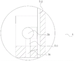
fig. 8 is an enlarged structural view of the invention at point B.
In the figure: 1. a hydraulic cylinder body; 2. a first oil inlet and outlet; 3. a second oil inlet and outlet; 4. a piston rod; 5. a guide sleeve; 6. a first piston body; 7. a protection mechanism; 71. a first movable chamber; 72. a second piston body; 73. a first connecting pipe; 74. a first connecting rod; 75. a first stopper; 76. an air outlet; 77. a converter body; 78. a nozzle; 79. a cold end pipe; 710. a hot end tube; 711. a vortex chamber; 712. a first control valve; 713. a second control valve; 714. a second connecting pipe; 715. a heat preservation cavity; 716. a third connecting pipe; 717. an auxiliary mechanism; 7171. a second movable chamber; 7172. a third piston body; 7173. a fourth connecting pipe; 7174. a second connecting rod; 7175. a second limiting block; 7176. a sealing mechanism; 71761. a seal ring; 71762. a wear ring; 7177. a first anti-collision layer; 7178. and a second anti-collision layer.
Detailed Description
The technical solutions in the embodiments of the present invention will be clearly and completely described below with reference to the drawings in the embodiments of the present invention, and it is obvious that the described embodiments are only a part of the embodiments of the present invention, and not all of the embodiments. All other embodiments, which can be derived by a person skilled in the art from the embodiments given herein without making any creative effort, shall fall within the protection scope of the present invention.
In the description of the present invention, it is to be understood that the terms "center", "longitudinal", "lateral", "length", "width", "thickness", "upper", "lower", "front", "rear", "left", "right", "vertical", "horizontal", "top", "bottom", "inner", "outer", "clockwise", "counterclockwise", and the like, indicate orientations and positional relationships based on those shown in the drawings, and are used only for convenience of description and simplicity of description, and do not indicate or imply that the device or element being referred to must have a particular orientation, be constructed and operated in a particular orientation, and thus, should not be considered as limiting the present invention.
Furthermore, the terms "first", "second" and "first" are used for descriptive purposes only and are not to be construed as indicating or implying relative importance or implicitly indicating the number of technical features indicated. Thus, features defined as "first", "second", may explicitly or implicitly include one or more of the described features. In the description of the present invention, "a plurality" means two or more unless specifically defined otherwise. Furthermore, the terms "mounted," "connected," and "connected" are to be construed broadly and may, for example, be fixedly connected, detachably connected, or integrally connected; can be mechanically or electrically connected; they may be connected directly or indirectly through intervening media, or they may be interconnected between two elements. The specific meanings of the above terms in the present invention can be understood in specific cases to those skilled in the art.
Referring to fig. 1 to 8, the present invention provides a hydraulic cylinder, which has a technical scheme:
a hydraulic cylinder, as shown in fig. 1 to 7, which includes a hydraulic cylinder body 1, a first oil inlet and outlet 2 is penetratingly arranged at a position, close to an upper end edge, of a right outer surface of the hydraulic cylinder body 1, a second oil inlet and outlet 3 is penetratingly arranged at a position, close to a lower end edge, of a left outer surface of the hydraulic cylinder body 1, a piston rod 4 is penetratingly arranged at a middle position of the lower outer surface of the hydraulic cylinder body 1, a guide sleeve 5 is fixedly arranged at a position, close to a lower end edge, of an outer surface of the piston rod 4, the guide sleeve 5 is positioned inside the hydraulic cylinder body 1, a first piston body 6 is fixedly arranged at a position, close to the upper end, of the outer surface of the piston rod 4, and a protection mechanism 7 is arranged at the left outer surface of the hydraulic cylinder body 1;
the protection mechanism 7 comprises a first movable cavity 71, a second piston body 72, a first connecting pipe 73, a first connecting rod 74, a first limiting block 75, an air outlet 76, a converter body 77, a nozzle 78, a cold end pipe 79, a hot end pipe 710, a swirl chamber 711, a first control valve 712, a second control valve 713, a second connecting pipe 714, a heat preservation cavity 715 and an auxiliary mechanism 717, wherein the second piston body 72 is movably connected inside the first movable cavity 71, the first connecting pipe 73 is connected through the position of the left inner surface of the first movable cavity 71 close to the lower end edge, one end of the first connecting pipe 73 far away from the first movable cavity 71 is connected through the second oil inlet/outlet 3, the first connecting rod 74 is fixedly connected at the middle position of the lower outer surface of the second piston body 72, and the first connecting rod 74 is fixedly connected with the piston rod 4 through the lower outer surface of the first movable cavity 71, a first limit block 75 is fixedly installed in the first movable cavity 71 close to the upper end of the first connecting pipe 73, the first limit block 75 is located at the lower end of the second piston body 72, an air outlet 76 is formed in the middle of the inner surface of the upper end of the first movable cavity 71 in a penetrating manner, a converter body 77 is arranged on the outer surface of the hydraulic cylinder body 1 close to the upper end of the air outlet 76 in a surrounding manner, a nozzle 78 is formed in the outer surface of the lower end of the converter body 77 in a penetrating manner at a position corresponding to the air outlet 76, a cold end pipe 79 is arranged in the converter body 77 close to the left side of the nozzle 78, a hot end pipe 710 is arranged in the converter body 77 close to the right side of the nozzle 78, a swirl chamber 711 is formed in the converter body 77 close to the upper end of the nozzle 78, a first control valve 712 is arranged in the converter body 77 close to the edge of one end of the cold end pipe 79, and a second control valve 713 is arranged in the converter body 77 close to the edge of one end of the hot end pipe 710, the cold end pipe 79 is close to one end of the first control valve 712 and is in threaded connection with the second connecting pipe 714, the outer surface of the hydraulic cylinder body 1 is provided with a heat preservation cavity 715, the heat preservation cavity 715 is located between the converter body 77 and the hydraulic cylinder body 1, the other end of the second connecting pipe 714 is in threaded connection with the heat preservation cavity 715, and the outer surface of the right side of the hydraulic cylinder body 1 is provided with an auxiliary mechanism 717.
Although the above-mentioned patent can prolong the service life of the hydraulic cylinder and reduce the maintenance frequency of the hydraulic cylinder, when the hydraulic cylinder is in a working environment with higher temperature, the oil temperature is increased to reduce the viscosity of the oil, so that the flow of the oil passing through the orifice or slit valve is increased, and the originally adjusted working speed is changed, thereby affecting the working stability, the invention, by arranging the first movable cavity 71, when the hydraulic cylinder body 1 works, the piston rod 4 moves towards the top direction in the hydraulic cylinder body 1, because the first connecting rod 74 is fixedly connected with the piston rod 4, at this time, the first connecting rod 74 moves upwards in the first movable cavity 71, aiming at the hydraulic cylinder body 1 which frequently does reciprocating motion, the motion speed of the piston rod 4 towards the top direction in the hydraulic cylinder body 1 is very fast, the upward motion speed of the first connecting rod 74 in the first movable cavity 71 is very fast, because the second piston body 72 is in sealed movable connection with the first movable cavity 71, in the process that the first connecting rod 74 moves upwards, air inside the first movable cavity 71 is compressed to form compressed air, the compressed air enters the nozzle 78 on the converter body 77 from the air outlet 76, then enters the nozzle 78, expands and accelerates in the nozzle 78, and is injected into the vortex chamber 711 from the tangential direction to form a free vortex, the rotating angular velocity of the free vortex is larger near the center, friction is generated between layers of the free vortex due to different angular velocities, the airflow angular velocity of the central part is the largest, the friction results are that energy is transferred to the airflow with lower angular velocity on the outer layer, the airflow of the central layer part loses energy, the kinetic energy is low, the velocity is reduced, the temperature is reduced, and the cold airflow required for refrigeration is led out from the cold end pipe 79 of the converter body 77 through the first control valve 712, meanwhile, the airflow of the outer layer part obtains momentum, the kinetic energy is increased, the airflow rubs with the inner wall of the converter body 77 to convert partial kinetic energy into heat energy, the heat energy is led out from the hot end pipe 710 of the converter body 77 through the second control valve 713 to form hot airflow, the flow and the temperature of the cold airflow and the hot airflow can be adjusted by controlling the first control valve 712 and the second control valve 713, cold airflow enters the heat preservation cavity 715 through the second connecting pipe 714 to cool the hydraulic cylinder body 1, the phenomenon that in a high-temperature working environment, the viscosity of oil is reduced due to the rise of the oil temperature, the flow of the oil passing through a throttling small hole or a slit type valve is increased, the originally adjusted working speed is changed, the working stability and the working precision of the hydraulic cylinder are ensured, the lubricating oil film between the relative movement surfaces of the hydraulic piston and the hydraulic rod is thinned after the oil temperature is increased and reduced, and the mechanical abrasion is reduced, the service life of oil and the normal work of pneumatic cylinder body 1 are guaranteed, the practicality and the commonality of totality are improved.
As a specific embodiment of the present invention, as shown in fig. 3 and 7, one end of the hot end pipe 710 near the second control valve 713 is screwed with a third connection pipe 716, and the other end of the third connection pipe 716 is screwed with the soak chamber 715.
In the working process, although the protection mechanism 7 can reduce the temperature of the hydraulic cylinder body 1 through cold airflow, and prevent the viscosity of oil from being reduced due to the increase of the temperature of the oil in a high-temperature working environment, so that the flow of the oil passing through the throttling small hole or the slit valve is increased, when the hydraulic cylinder body 1 is in a low-temperature working environment, the hydraulic cylinder can slowly act due to the phenomenon of grease condensation to a certain degree, so that the viscosity of the hydraulic oil is large, the fluidity is poor, and the practical use is affected, the invention is connected with the hot end pipe 710 through the third connecting pipe 716, when the temperature of the hydraulic cylinder body 1 needs to be raised, because the second connecting pipe 714 is in threaded connection with the heat preservation cavity 715, the second connecting pipe 714 is separated from the heat preservation cavity 715 through rotation, the delivery of cold air is stopped, the third connecting pipe 716 is connected with the heat preservation cavity 715, and according to the embodiment, at this time, the hot air flows into the heat preservation cavity 715 through the third connecting pipe 716 to raise the temperature of the hydraulic cylinder body 1, prevent in the operational environment that the temperature is low, the grease phenomenon appears in its inside hydraulic oil, guarantees the viscosity and the mobility of hydraulic oil, guarantees the normal work and the work efficiency of pneumatic cylinder body 1, improves the practicality and the commonality of totality.
As a specific embodiment of the present invention, as shown in fig. 3, the temperature inside the heat preservation chamber 715 is in a range of 20 ° to 70 ° for ensuring the temperature inside the hydraulic cylinder body 1 is in a range of 30 ° to 60 ° for providing an optimum working temperature for the hydraulic oil.
When the hydraulic cylinder works, although the protection mechanism 7 can cool the hydraulic cylinder body 1 through cold airflow, the phenomenon that the viscosity of oil is reduced due to the rise of the oil temperature in a high-temperature working environment is prevented, so that the flow of oil passing through the throttling small hole or the slit valve is increased, at the moment, the temperature inside the heat preservation cavity 715 is not necessarily the optimal working temperature of the hydraulic oil, and through the first control valve 712 and the second control valve 713, when the temperature needs to be lowered, the temperature of cold air entering the heat preservation cavity 715 is controlled to be 10-30 degrees, if the temperature needs to be raised, the temperature of hot air entering the heat preservation cavity 715 is controlled to be 40-70 degrees, so that the temperature inside the hydraulic cylinder body 1 is ensured to be 30-60 degrees, the optimal working temperature is provided for the hydraulic oil, and the overall practicability is improved.
As a specific embodiment of the present invention, as shown in fig. 3, the auxiliary mechanism 717 includes a second movable chamber 7171, a third piston body 7172, a fourth connecting pipe 7173, a second connecting rod 7174, a second stopper 7175 and a sealing mechanism 7176, the third piston body 7172 is movably connected to the inside of the second movable chamber 7171, the fourth connecting pipe 7173 is connected to the inner surface of the left side of the second movable chamber 7171 near the lower edge, one end of the fourth connecting pipe 7173 far from the second movable chamber 7171 is connected to the second oil inlet/outlet port 3 in a penetrating manner, the second connecting rod 7174 is fixedly connected to the middle position of the outer surface of the lower end of the third piston body 7172 in a penetrating manner, the second connecting rod 7174 is fixedly connected to the piston rod 4 through the outer surface of the lower end of the second movable chamber 7171, a gap exists between the first connecting rod 7174 and the second movable chamber 7171, the second stopper 7175 is fixedly installed inside the second movable chamber 7171 near the lower end of the fourth connecting pipe 7173, the second stopper 7175 is located at the upper end of the third piston body 7172, and the sealing mechanism 7176 is disposed around the second piston body 72 at the middle position of the side surface of the third piston body 7172.
When the hydraulic oil cylinder works, the first piston body 6 is moved by the pressure difference between the two sides of the hydraulic oil cylinder to drive the piston rod 4 to reciprocate, the running speed and force are controlled by the flow rate of the hydraulic oil, after long-term use, when the flow rate of the hydraulic oil cannot be changed, the power provided by the hydraulic rod cannot be changed, when the flow rate of the hydraulic oil is smaller, the power provided by the hydraulic rod is smaller, the liquid flow rate of the hydraulic oil cylinder with smaller volume is smaller, and therefore the smaller hydraulic oil cylinder cannot provide larger power, by arranging the second movable cavity 7171, when the piston rod 4 needs to move upwards, the first oil inlet and outlet 2 takes oil, and when the second oil inlet and outlet 3 returns oil, the hydraulic oil enters the first movable cavity 71 through the first connecting pipe 73, and extrudes the second piston body 72 to move upwards in the first movable cavity 71, because the first connecting rod 74 is fixedly connected with the piston rod 4, the piston rod 4 is driven to move upwards through the first connecting rod 74 in the moving process, so that a directional upward force is provided for the piston rod 4, an auxiliary effect is achieved, when the piston rod 4 needs to move downwards, oil returns from the first oil inlet and outlet port 2, and oil enters from the second oil inlet and outlet port 3, hydraulic oil enters into the second movable cavity 7171 through the fourth connecting pipe 7173 to extrude the third piston body 7172 to move upwards, and because the second connecting rod 7174 is fixedly connected with the piston rod 4, the piston rod 4 is driven to move downwards through the second connecting rod 7174 in the moving process, so that a directional downward force is provided for the piston rod 4, and therefore power is provided for the movement of the piston rod 4, the piston rod 4 with a smaller size also has larger power, and the overall practicability is improved.
As a specific embodiment of the present invention, as shown in fig. 3, a first anti-collision layer 7177 is fixedly installed on the upper end of the inner surface of the first movable chamber 71, and a second anti-collision layer 7178 is fixedly installed on the lower end of the inner surface of the second movable chamber 7171.
During operation, the first connecting rod 74 moves upwards to drive the second piston body 72 to move, the first connecting rod 74 moves upwards at a certain speed, so that the second piston body 72 has a certain speed, when moving to the top end of the first movable cavity 71, the second piston body 72 generates impact force to the top end of the first movable cavity 71, the first movable cavity 71 is damaged due to long-time impact, the working effect of the protection mechanism 7 is affected, when moving upwards, the second connecting rod 7174 drives the third piston body 7172 to move, when moving to the top end of the second movable cavity 7171, the second connecting rod 7174 moves upwards at a certain speed, so that the third piston body 7172 has a certain speed, when moving to the top end of the second movable cavity 7171, the third piston body 7172 generates impact force to the top end of the second movable cavity 7171, and the second movable cavity 7171 is damaged due to long-time impact, the working effect of the auxiliary mechanism 717 is influenced, the first anti-collision layer 7177 is fixedly arranged at the upper end of the inner surface of the first movable cavity 71, the second anti-collision layer 7178 is fixedly arranged at the lower end of the inner surface of the second movable cavity 7171, the top end of the first movable cavity 71 and the top end of the second movable cavity 7171 are protected from being influenced by impact force, and the normal work of the protection mechanism 7 and the auxiliary mechanism 717 is guaranteed.
As a specific embodiment of the present invention, as shown in fig. 8, the sealing mechanism 7176 includes a sealing ring 71761 and a wear-resistant ring 71762, the sealing ring 71761 is disposed around the middle position of the side surfaces of the second piston body 72 and the third piston body 7172, and the wear-resistant ring 71762 is disposed around the side surfaces of the second piston body 72 and the third piston body 7172 near the lower end of the sealing ring 71761.
During operation, after long-term use, the sealing performance between the second piston body 72 and the first movable cavity 71, and between the third piston body 7172 and the second movable cavity 7171 is reduced, and the working effect of the protection mechanism 7 and the auxiliary mechanism 717 is affected.
The working principle is as follows: according to the invention, by arranging the first movable cavity 71, when the hydraulic cylinder body 1 works, in the process that the piston rod 4 moves towards the top in the hydraulic cylinder body 1, as the first connecting rod 74 is fixedly connected with the piston rod 4, and at the moment, the first connecting rod 74 moves upwards in the first movable cavity 71, aiming at the hydraulic cylinder body 1 which frequently reciprocates, the movement speed of the piston rod 4 towards the top in the hydraulic cylinder body 1 is very high, the upward movement speed of the first connecting rod 74 in the first movable cavity 71 is very high, as the second piston body 72 is in sealed movable connection with the first movable cavity 71, in the process that the first connecting rod 74 moves upwards, air in the first movable cavity 71 is compressed to form compressed air, and the compressed air enters the nozzle 78 on the converter body 77 from the air outlet 76, enters the nozzle 78 at the moment, expands and accelerates in the nozzle 78, the heat energy is injected into the vortex chamber 711 from the tangential direction to form a free vortex, the rotation angular velocity of the free vortex is larger closer to the center, friction is generated between layers of the free vortex due to different angular velocities, the airflow angular velocity of the central part is the largest, the friction results are that energy is transferred to the airflow with lower angular velocity of the outer layer, the airflow of the central layer part loses energy, kinetic energy is low, velocity is reduced, and temperature is reduced, the cold airflow required for refrigeration is obtained by leading out the cold end pipe 79 of the converter body 77 through the first control valve 712, meanwhile, the airflow of the outer layer part obtains momentum, kinetic energy is increased, the kinetic energy is rubbed with the inner wall of the converter body 77, part of the kinetic energy is converted into heat energy, the heat energy is led out from the hot end pipe 710 of the converter body 77 through the second control valve 713, hot airflow is formed, and the flow and temperature of the cold airflow and the hot airflow can be adjusted by controlling the first control valve 712 and the second control valve 713, the cold air flow enters the heat preservation cavity 715 through the second connecting pipe 714 to cool the hydraulic cylinder body 1, so as to prevent the viscosity of oil from being reduced due to the rise of oil temperature in a high-temperature working environment, so that the flow of the oil passing through the throttling small hole or the slit valve is increased, the originally adjusted working speed is changed, the working stability and the working precision of the hydraulic cylinder body are ensured, after the oil temperature is prevented from rising and the viscosity is reduced, a lubricating oil film between the relative motion surfaces of the hydraulic piston and the hydraulic rod is thinned, the mechanical abrasion is reduced, the service life of the oil and the normal work of the hydraulic cylinder body 1 are ensured, and the overall practicability and universality are improved. Because the first connecting rod 74 is fixedly connected with the piston rod 4, the piston rod 4 is driven to move upwards through the first connecting rod 74 in the moving process, so that a directional upward force is provided for the piston rod 4, an auxiliary effect is achieved, when the piston rod 4 needs to move downwards, oil returns from the first oil inlet and outlet port 2, and oil enters from the second oil inlet and outlet port 3, hydraulic oil enters into the second movable cavity 7171 through the fourth connecting pipe 7173 to extrude the third piston body 7172 to move upwards, and because the second connecting rod 7174 is fixedly connected with the piston rod 4, the piston rod 4 is driven to move downwards through the second connecting rod 7174 in the moving process, so that a directional downward force is provided for the piston rod 4, and therefore power is provided for the movement of the piston rod 4, the piston rod 4 with a smaller size also has larger power, and the overall practicability is improved.
The electric elements in the document are electrically connected with an external main controller and 220V mains supply through a transformer, the main controller can be a conventional known device controlled by a computer and the like, the product model provided by the invention is only used according to the structural characteristics of the product, the product can be adjusted and modified after being purchased, so that the product is more matched with and accords with the technical scheme of the invention, the product model is a technical scheme of the optimal application of the technical scheme, the product model can be replaced and modified according to the required technical parameters, and the product model is familiar to the technical personnel in the field, so that the technical scheme provided by the invention can clearly obtain the corresponding use effect.
Although embodiments of the present invention have been shown and described, it will be appreciated by those skilled in the art that changes, modifications, substitutions and alterations can be made in these embodiments without departing from the principles and spirit of the invention, the scope of which is defined in the appended claims and their equivalents.
Claims (6)
1. The utility model provides a hydraulic cylinder, includes pneumatic cylinder body (1), its characterized in that: a first oil inlet and outlet (2) is arranged on the outer surface of the right side of the hydraulic cylinder body (1) close to the edge of the upper end in a penetrating manner, a second oil inlet and outlet (3) is arranged on the outer surface of the left side of the hydraulic cylinder body (1) close to the edge of the lower end in a penetrating manner, a piston rod (4) is arranged in the middle of the outer surface of the lower end of the hydraulic cylinder body (1) in a penetrating manner, a guide sleeve (5) is fixedly arranged on the outer surface of the piston rod (4) close to the edge of the lower end in a penetrating manner, the guide sleeve (5) is positioned in the hydraulic cylinder body (1), a first piston body (6) is fixedly arranged on the outer surface of the piston rod (4) close to the upper end in a penetrating manner, and a protection mechanism (7) is arranged on the outer surface of the left side of the hydraulic cylinder body (1);
the protection mechanism (7) comprises a first movable cavity (71), a second piston body (72), a first connecting pipe (73), a first connecting rod (74), a first limiting block (75), an air outlet (76), a converter body (77), a nozzle (78), a cold end pipe (79), a hot end pipe (710), a vortex chamber (711), a first control valve (712), a second control valve (713), a second connecting pipe (714), a heat preservation cavity (715) and an auxiliary mechanism (717), wherein the inner part of the first movable cavity (71) is movably connected with the second piston body (72), the inner surface of the left side of the first movable cavity (71) is close to the edge of the lower end and is in through connection with the first connecting pipe (73), one end of the first connecting pipe (73), which is far away from the first movable cavity (71), is in through connection with the second oil inlet/outlet (3), and the middle position of the outer surface of the lower end of the second piston body (72) is fixedly connected with the first connecting rod (74), the hydraulic cylinder is characterized in that a first connecting rod (74) penetrates through the outer surface of the lower end of a first movable cavity (71) and is fixedly connected with a piston rod (4), a first limiting block (75) is fixedly installed at the upper end, close to a first connecting pipe (73), of the interior of the first movable cavity (71), the first limiting block (75) is located at the lower end of a second piston body (72), an air outlet (76) penetrates through the middle position of the inner surface of the upper end of the first movable cavity (71), a converter body (77) is arranged at the upper end, close to the air outlet (76), of the outer surface of the hydraulic cylinder body (1) in a surrounding mode, a nozzle (78) penetrates through the outer surface of the lower end of the converter body (77) and corresponds to the air outlet (76), a cold end pipe (79) is arranged on the left side, close to the nozzle (78), of the interior of the converter body (77), a hot end pipe (710) is arranged on the right side, close to the nozzle (78), swirl chamber (711) are seted up to the inside upper end that is close to nozzle (78) of converter body (77), the inside one end border position that is close to cold end pipe (79) of converter body (77) sets up first control valve (712), the inside one end border position that is close to hot end pipe (710) of converter body (77) sets up second control valve (713), cold end pipe (79) are close to one end threaded connection second connecting pipe (714) of first control valve (712), the surface of pneumatic cylinder body (1) sets up heat preservation chamber (715), heat preservation chamber (715) are located between converter body (77) and pneumatic cylinder body (1), the other end and the heat preservation chamber (715) threaded connection of second connecting pipe (714), the right side surface of pneumatic cylinder body (1) sets up complementary unit (717).
2. A hydraulic cylinder as claimed in claim 1, characterized by: one end of the hot end pipe (710) close to the second control valve (713) is in threaded connection with a third connecting pipe (716), and the other end of the third connecting pipe (716) is in threaded connection with the heat preservation cavity (715).
3. A hydraulic cylinder as claimed in claim 1, characterized by: the temperature range of the interior of the heat preservation cavity (715) is 20-70 degrees, the temperature of the interior of the hydraulic cylinder body (1) is ensured to be 30-60 degrees, and the optimal working temperature is provided for hydraulic oil.
4. A hydraulic cylinder as claimed in claim 1, characterized by: the auxiliary mechanism (717) comprises a second movable cavity (7171), a third piston body (7172), a fourth connecting pipe (7173), a second connecting rod (7174), a second limiting block (7175) and a sealing mechanism (7176), the inside of the second movable cavity (7171) is movably connected with the third piston body (7172), the inner surface of the left side of the second movable cavity (7171) is close to the lower end edge and is connected with the fourth connecting pipe (7173) in a penetrating way, one end of the fourth connecting pipe (7173) far away from the second movable cavity (7171) is connected with the second oil inlet and outlet (3) in a penetrating way, the middle position of the outer surface of the lower end of the third piston body (7172) is fixedly connected with the second connecting rod (7174), the second connecting rod (7174) penetrates through the outer surface of the lower end of the second movable cavity (7171) and is fixedly connected with the piston rod (4), and a gap exists between the first connecting rod (7174) and the second movable cavity (7171), and a second limit block (7175) is fixedly arranged in the second movable cavity (7171) and close to the lower end of the fourth connecting pipe (7173), the second limit block (7175) is positioned at the upper end of the third piston body (7172), and the middle positions of the side surfaces of the third piston body (7172) of the second piston body (72) are all surrounded by sealing mechanisms (7176).
5. A hydraulic cylinder according to claim 4, characterized in that: a first anti-collision layer (7177) is fixedly arranged at the upper end of the inner surface of the first movable cavity (71), and a second anti-collision layer (7178) is fixedly arranged at the lower end of the inner surface of the second movable cavity (7171).
6. A hydraulic cylinder according to claim 4, characterized in that: the sealing mechanism (7176) comprises a sealing ring (71761) and a wear-resisting ring (71762), wherein the sealing ring (71761) is arranged in a surrounding mode at the middle position of the side surfaces of the second piston body (72) and the third piston body (7172), and the wear-resisting ring (71762) is arranged in a surrounding mode at the position, close to the lower end of the sealing ring (71761), of the side surfaces of the second piston body (72) and the third piston body (7172).
Priority Applications (1)
| Application Number | Priority Date | Filing Date | Title |
|---|---|---|---|
| CN202111051584.1A CN113883121A (en) | 2021-09-08 | 2021-09-08 | Hydraulic oil cylinder |
Applications Claiming Priority (1)
| Application Number | Priority Date | Filing Date | Title |
|---|---|---|---|
| CN202111051584.1A CN113883121A (en) | 2021-09-08 | 2021-09-08 | Hydraulic oil cylinder |
Publications (1)
| Publication Number | Publication Date |
|---|---|
| CN113883121A true CN113883121A (en) | 2022-01-04 |
Family
ID=79008770
Family Applications (1)
| Application Number | Title | Priority Date | Filing Date |
|---|---|---|---|
| CN202111051584.1A Pending CN113883121A (en) | 2021-09-08 | 2021-09-08 | Hydraulic oil cylinder |
Country Status (1)
| Country | Link |
|---|---|
| CN (1) | CN113883121A (en) |
Cited By (1)
| Publication number | Priority date | Publication date | Assignee | Title |
|---|---|---|---|---|
| CN115076187A (en) * | 2022-07-08 | 2022-09-20 | 常州力安液压设备有限公司 | A composite multi-section oil cylinder and its electro-hydraulic control system |
-
2021
- 2021-09-08 CN CN202111051584.1A patent/CN113883121A/en active Pending
Cited By (1)
| Publication number | Priority date | Publication date | Assignee | Title |
|---|---|---|---|---|
| CN115076187A (en) * | 2022-07-08 | 2022-09-20 | 常州力安液压设备有限公司 | A composite multi-section oil cylinder and its electro-hydraulic control system |
Similar Documents
| Publication | Publication Date | Title |
|---|---|---|
| CN202160055U (en) | Electric servo actuator adopting lubricating device | |
| CN103925200B (en) | A kind of pneumatic diaphragm pump | |
| CN106762503A (en) | Digital distribution and speed governing type low speed axial plunger pump | |
| CN117759602B (en) | High-precision hydraulic cylinder | |
| CN205330918U (en) | Interior cold type compressor clearance tolerance governing system actuating mechanism | |
| CN110206781A (en) | A kind of asymmetric four-side formula digital fluid cylinder | |
| CN108869680A (en) | A kind of electric cylinder with circulating cooling channel | |
| CN113915098B (en) | Linear compressor with adjustable cylinder volume | |
| CN108488139B (en) | A kind of hydraulic cylinder | |
| CN115681438A (en) | Novel efficient gas-liquid loading displacement pump and constant-pressure constant-speed system | |
| CN116792408B (en) | Hydrostatic guideway throttling structure | |
| CN220910482U (en) | Electric flow regulating and pressure regulating valve | |
| CN201382042Y (en) | Segmental-type piston double-action short-stroke hydraulic cylinder device | |
| CN219911803U (en) | Electric pilot piston type straight travel regulating valve | |
| CN115095678B (en) | Air valve device and pneumatic equipment | |
| CN203051024U (en) | Flow-adjusting injection pump | |
| CN112160845B (en) | Stirling engine and one-way throttling type piston dynamic sealing mechanism | |
| CN110940085B (en) | Ejectors, Chilled Beam Terminals, Chilled Beam Systems | |
| CN110779672B (en) | A high frequency fatigue actuation device | |
| CN222746584U (en) | Oil cylinder piston of suction valve | |
| CN208793232U (en) | The fuel supply flow rate self-regulation sliding valve structure of helical-lobe compressor | |
| CN117090760A (en) | Piston pump with stroke dynamically regulated and controlled and stroke control method | |
| CN224187978U (en) | Cylindrical cam mechanism | |
| CN120100917B (en) | A two-stage low torque flow regulating and pressure regulating valve | |
| CN117052650B (en) | Reciprocating pump power device capable of automatically injecting oil |
Legal Events
| Date | Code | Title | Description |
|---|---|---|---|
| PB01 | Publication | ||
| PB01 | Publication | ||
| SE01 | Entry into force of request for substantive examination | ||
| SE01 | Entry into force of request for substantive examination |