CN113858001A - Grinding method - Google Patents
Grinding method Download PDFInfo
- Publication number
- CN113858001A CN113858001A CN202111199185.XA CN202111199185A CN113858001A CN 113858001 A CN113858001 A CN 113858001A CN 202111199185 A CN202111199185 A CN 202111199185A CN 113858001 A CN113858001 A CN 113858001A
- Authority
- CN
- China
- Prior art keywords
- grinding wheel
- workpiece
- grinding
- control unit
- side edge
- Prior art date
- Legal status (The legal status is an assumption and is not a legal conclusion. Google has not performed a legal analysis and makes no representation as to the accuracy of the status listed.)
- Pending
Links
- 238000000034 method Methods 0.000 title claims abstract description 40
- 230000000630 rising effect Effects 0.000 claims description 6
- 230000005540 biological transmission Effects 0.000 description 20
- 238000003754 machining Methods 0.000 description 8
- 230000002457 bidirectional effect Effects 0.000 description 5
- 239000003921 oil Substances 0.000 description 4
- XUIMIQQOPSSXEZ-UHFFFAOYSA-N Silicon Chemical compound [Si] XUIMIQQOPSSXEZ-UHFFFAOYSA-N 0.000 description 3
- 238000010586 diagram Methods 0.000 description 3
- 230000000694 effects Effects 0.000 description 3
- 229910052710 silicon Inorganic materials 0.000 description 3
- 239000010703 silicon Substances 0.000 description 3
- 230000001174 ascending effect Effects 0.000 description 2
- 238000001514 detection method Methods 0.000 description 2
- 230000002035 prolonged effect Effects 0.000 description 2
- 229910000831 Steel Inorganic materials 0.000 description 1
- 230000000712 assembly Effects 0.000 description 1
- 238000000429 assembly Methods 0.000 description 1
- 238000006073 displacement reaction Methods 0.000 description 1
- 238000012986 modification Methods 0.000 description 1
- 230000004048 modification Effects 0.000 description 1
- 229910021421 monocrystalline silicon Inorganic materials 0.000 description 1
- 239000011295 pitch Substances 0.000 description 1
- 230000003068 static effect Effects 0.000 description 1
- 239000010959 steel Substances 0.000 description 1
Images




Classifications
-
- B—PERFORMING OPERATIONS; TRANSPORTING
- B24—GRINDING; POLISHING
- B24B—MACHINES, DEVICES, OR PROCESSES FOR GRINDING OR POLISHING; DRESSING OR CONDITIONING OF ABRADING SURFACES; FEEDING OF GRINDING, POLISHING, OR LAPPING AGENTS
- B24B27/00—Other grinding machines or devices
- B24B27/0076—Other grinding machines or devices grinding machines comprising two or more grinding tools
-
- B—PERFORMING OPERATIONS; TRANSPORTING
- B24—GRINDING; POLISHING
- B24B—MACHINES, DEVICES, OR PROCESSES FOR GRINDING OR POLISHING; DRESSING OR CONDITIONING OF ABRADING SURFACES; FEEDING OF GRINDING, POLISHING, OR LAPPING AGENTS
- B24B41/00—Component parts such as frames, beds, carriages, headstocks
- B24B41/06—Work supports, e.g. adjustable steadies
-
- B—PERFORMING OPERATIONS; TRANSPORTING
- B24—GRINDING; POLISHING
- B24B—MACHINES, DEVICES, OR PROCESSES FOR GRINDING OR POLISHING; DRESSING OR CONDITIONING OF ABRADING SURFACES; FEEDING OF GRINDING, POLISHING, OR LAPPING AGENTS
- B24B47/00—Drives or gearings; Equipment therefor
- B24B47/20—Drives or gearings; Equipment therefor relating to feed movement
-
- B—PERFORMING OPERATIONS; TRANSPORTING
- B24—GRINDING; POLISHING
- B24B—MACHINES, DEVICES, OR PROCESSES FOR GRINDING OR POLISHING; DRESSING OR CONDITIONING OF ABRADING SURFACES; FEEDING OF GRINDING, POLISHING, OR LAPPING AGENTS
- B24B49/00—Measuring or gauging equipment for controlling the feed movement of the grinding tool or work; Arrangements of indicating or measuring equipment, e.g. for indicating the start of the grinding operation
- B24B49/006—Measuring or gauging equipment for controlling the feed movement of the grinding tool or work; Arrangements of indicating or measuring equipment, e.g. for indicating the start of the grinding operation taking regard of the speed
-
- B—PERFORMING OPERATIONS; TRANSPORTING
- B24—GRINDING; POLISHING
- B24B—MACHINES, DEVICES, OR PROCESSES FOR GRINDING OR POLISHING; DRESSING OR CONDITIONING OF ABRADING SURFACES; FEEDING OF GRINDING, POLISHING, OR LAPPING AGENTS
- B24B7/00—Machines or devices designed for grinding plane surfaces on work, including polishing plane glass surfaces; Accessories therefor
- B24B7/20—Machines or devices designed for grinding plane surfaces on work, including polishing plane glass surfaces; Accessories therefor characterised by a special design with respect to properties of the material of non-metallic articles to be ground
- B24B7/22—Machines or devices designed for grinding plane surfaces on work, including polishing plane glass surfaces; Accessories therefor characterised by a special design with respect to properties of the material of non-metallic articles to be ground for grinding inorganic material, e.g. stone, ceramics, porcelain
- B24B7/228—Machines or devices designed for grinding plane surfaces on work, including polishing plane glass surfaces; Accessories therefor characterised by a special design with respect to properties of the material of non-metallic articles to be ground for grinding inorganic material, e.g. stone, ceramics, porcelain for grinding thin, brittle parts, e.g. semiconductors, wafers
-
- B—PERFORMING OPERATIONS; TRANSPORTING
- B24—GRINDING; POLISHING
- B24B—MACHINES, DEVICES, OR PROCESSES FOR GRINDING OR POLISHING; DRESSING OR CONDITIONING OF ABRADING SURFACES; FEEDING OF GRINDING, POLISHING, OR LAPPING AGENTS
- B24B9/00—Machines or devices designed for grinding edges or bevels on work or for removing burrs; Accessories therefor
- B24B9/02—Machines or devices designed for grinding edges or bevels on work or for removing burrs; Accessories therefor characterised by a special design with respect to properties of materials specific to articles to be ground
- B24B9/06—Machines or devices designed for grinding edges or bevels on work or for removing burrs; Accessories therefor characterised by a special design with respect to properties of materials specific to articles to be ground of non-metallic inorganic material, e.g. stone, ceramics, porcelain
- B24B9/065—Machines or devices designed for grinding edges or bevels on work or for removing burrs; Accessories therefor characterised by a special design with respect to properties of materials specific to articles to be ground of non-metallic inorganic material, e.g. stone, ceramics, porcelain of thin, brittle parts, e.g. semiconductors, wafers
Landscapes
- Engineering & Computer Science (AREA)
- Mechanical Engineering (AREA)
- Chemical & Material Sciences (AREA)
- Ceramic Engineering (AREA)
- Inorganic Chemistry (AREA)
- Grinding Of Cylindrical And Plane Surfaces (AREA)
Abstract
The invention discloses a grinding method, which comprises the following steps: the control unit drives the workpiece clamping and rotating assembly to clamp the workpiece; the control unit drives the first rotary power source to drive the first grinding wheel to rotate circumferentially, and drives the first lifting translation assembly to drive the first grinding wheel to contact the workpiece; the control unit drives the first lifting translation assembly to drive the first grinding wheel to ascend or descend so as to grind the side edge of the workpiece; the control unit drives the workpiece clamping and rotating assembly to drive the side edge of the workpiece ground by the first grinding wheel to face the second grinding wheel; the control unit drives a second rotary power source to drive a second grinding wheel to rotate circumferentially; the control unit drives the second lifting translation assembly to drive the second grinding wheel to ascend or descend so as to grind the side edge of the workpiece ground by the first grinding wheel; the technical scheme can reduce the return time and the waiting time and improve the efficiency of grinding operation.
Description
Technical Field
The invention relates to the technical field of grinding, in particular to a grinding method.
Background
The machining processes of the silicon rod cutting, the corner grinding and the plane grinding are usually three independent procedures, and the whole machining process needs to be completed in the same equipment. In actual operation, generally, after a wire squarer is used to perform a squaring operation on a single crystal silicon rod, the silicon rod after the squaring operation is sent to a grinding mechanism to perform a round-corner and plane grinding operation. The existing grinding mechanism has poor grinding method and affects the efficiency of grinding operation.
Disclosure of Invention
Therefore, it is necessary to provide a grinding method to solve the problem of poor efficiency of grinding operation.
In order to achieve the above object, the present embodiment provides a grinding method applied to a grinding mechanism;
the grinding mechanism comprises a workpiece clamping rotating assembly, a first lifting and translation assembly, a first rotary power source, a first grinding wheel, a second lifting and translation assembly, a first rotary power source, a second grinding wheel and a control unit, wherein the first lifting and translation assembly is arranged on one side of the workpiece clamping rotating assembly, the first grinding wheel is arranged on the first lifting and translation assembly through the first rotary power source, the second lifting and translation assembly is arranged on the other side of the workpiece clamping rotating assembly, the second grinding wheel is arranged on the second lifting and translation assembly through the second rotary power source, and the mesh number of the first grinding wheel is smaller than that of the second grinding wheel;
the method comprises the following steps:
the control unit drives the workpiece clamping and rotating assembly to clamp the workpiece;
the control unit drives the first rotary power source to drive the first grinding wheel to rotate in the circumferential direction, the rotating shaft of the first grinding wheel rotating in the circumferential direction is perpendicular to the rotating shaft of the workpiece rotating in the circumferential direction, and the control unit drives the first lifting translation assembly to drive the first grinding wheel to contact the workpiece;
the control unit drives the first lifting translation assembly to drive the first grinding wheel to ascend or descend so as to grind the side edge of the workpiece;
the control unit drives the first lifting translation assembly to drive the first grinding wheel to translate in the direction far away from the workpiece, and drives the workpiece clamping and rotating assembly to drive the workpiece to rotate circumferentially, so that the side edge of the workpiece ground by the first grinding wheel faces the second grinding wheel;
the control unit drives the second rotary power source to drive the second grinding wheel to rotate circumferentially, the rotating shaft of the second grinding wheel rotating circumferentially is parallel to the rotating shaft of the first grinding wheel rotating circumferentially, and the control unit drives the second lifting translation assembly to drive the second grinding wheel to contact the side edge of the workpiece ground by the first grinding wheel;
the control unit drives the second lifting translation assembly to drive the second grinding wheel to ascend or descend so as to grind the side edge of the workpiece ground by the first grinding wheel.
Further, the method also comprises the following steps:
the control unit drives the first lifting translation assembly to drive the first grinding wheel to contact a side edge of the workpiece which is not ground by the first grinding wheel or the second grinding wheel;
the control unit drives the first lifting translation assembly to drive the first grinding wheel to ascend or descend so as to grind the lateral edge of the workpiece which is not ground by the first grinding wheel or the second grinding wheel.
Further, when the step "the control unit drives the first lifting and translation assembly to drive the first grinding wheel to ascend or descend to grind the side edge of the workpiece", the method further comprises the following steps:
aligning the diagonal line of the side edge of the workpiece to a rotating shaft of a first grinding wheel in circumferential rotation, wherein the first grinding wheel is annular, and the control unit drives the workpiece clamping rotating assembly to drive the workpiece to rotate and rub an inner ring of the first grinding wheel;
when the step "the control unit drives the second lifting translation assembly to drive the second grinding wheel to ascend or descend to grind the side edge of the workpiece ground by the first grinding wheel", the method further comprises the following steps:
the diagonal line of the side edge of the workpiece is aligned to a rotating shaft of a second grinding wheel in circumferential rotation, the second grinding wheel is annular, and the control unit drives the workpiece clamping rotating assembly to drive the workpiece to rotate and rub an inner ring of the second grinding wheel.
Further, after the first grinding wheel grinds the side edge of the workpiece which is not ground by the first grinding wheel or the second grinding wheel for a preset distance, the second grinding wheel grinds the side edge of the workpiece which is ground by the first grinding wheel.
Further, the rotating speed of the workpiece is 1 rpm/min-100 rpm/min.
Further, the feeding speed of the first grinding wheel for grinding the side edge of the workpiece by ascending or descending is 500 mm/min; or:
the feed rate of the second grinding wheel rising or falling to grind the side edge on the workpiece was 400 mm/min.
Further, when the step "the control unit drives the first rotary power source to drive the first grinding wheel to rotate circumferentially", the method further comprises the following steps:
the speed of the first grinding wheel rotating in the circumferential direction is 3000 rpm/min-5000 rpm/min.
Furthermore, the mesh number of the first grinding wheel is 20-300, and the mesh number of the second grinding wheel is 300-600.
Further, the feeding speed of the first grinding wheel for grinding the side edge of the workpiece by ascending or descending is 1000 mm/min; or:
the feed rate of the second grinding wheel rising or falling to grind the side edge on the workpiece was 1200 mm/min.
Further, the workpiece clamping and rotating assembly comprises an upright post and a clamping device, and the clamping device is connected with the front side surface of the upright post in a sliding manner; the first lifting translation assembly comprises a first support, and one side of the first support is connected with the right side surface of the upright column in a sliding manner; the second lifting translation assembly comprises a second support, and one side of the second support is connected with the left side face of the upright column in a sliding mode.
Different from the prior art, in the technical scheme, the mesh number of the first grinding wheel is smaller than that of the second grinding wheel, and the first grinding wheel and the second grinding wheel respectively perform rough machining and fine machining on the workpiece, so that the grinding quality can be improved; the first grinding wheel and the second grinding wheel carry out grinding operation on the workpiece together, so that the return time and the waiting time can be reduced, the efficiency of the grinding operation is improved, the grinding mechanism is prevented from being broken down due to the fact that the rotational inertia of the workpiece is too large, and the service life of the grinding mechanism is prolonged.
Drawings
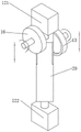
FIG. 1 is a schematic structural view of a grinding mechanism according to the present embodiment;
FIG. 2 is a schematic structural diagram of the clamping device in the present embodiment;
FIG. 3 is a schematic structural view of the second lifting and translating assembly and the second grinding wheel in the present embodiment;
FIG. 4 is a schematic structural view of the first lifting and translating assembly and the first grinding wheel in the present embodiment;
FIG. 5 is a schematic structural diagram of the first grinding wheel and the second grinding wheel for grinding a workpiece according to the present embodiment;
FIG. 6 is a schematic cross-sectional view illustrating a first grinding wheel and a second grinding wheel grinding a workpiece according to the present embodiment;
FIG. 7 is a schematic diagram illustrating a first grinding wheel and a second grinding wheel grinding a workpiece to form a fillet in the present embodiment;
fig. 8 is a schematic structural view of a second grinding wheel in the present embodiment.
Description of reference numerals:
10. a grinding mechanism;
101. a workpiece clamping and rotating assembly;
102. a first lifting translation assembly;
103. a second lifting translation assembly;
11. a column;
12. a clamping device;
121. a first clamping member; 122. a second clamping member; 123. a first transmission member;
13. a first grinding wheel;
14. a first bracket;
15. a first rotary power source;
16. a second grinding wheel;
17. a second rotary power source;
18. a second bracket;
20. and (5) a workpiece.
Detailed Description
To explain technical contents, structural features, and objects and effects of the technical solutions in detail, the following detailed description is given with reference to the accompanying drawings in conjunction with the embodiments.
Referring to fig. 1 to 8, the grinding mechanism 10 of the present embodiment includes a workpiece clamping and rotating assembly 101, a first lifting and translating assembly 102, a first rotary power source 15, a first grinding wheel 13, a second lifting and translating assembly 103, a first rotary power source 15, a second grinding wheel 16, and a control unit. The first lifting and translation assembly 102 is arranged on one side of the workpiece clamping and rotating assembly 101, and the first lifting and translation assembly 102 is used for driving the first grinding wheel 13 to lift and translate. The first grinding wheel 13 is disposed on the first lifting and translating assembly 102 through a first rotary power source 15, and the first rotary power source 15 is configured to rotate the first grinding wheel 13 along a rotation axis (i.e., a central axis) thereof. The second lifting and translation assembly 103 is arranged on the other side of the workpiece clamping and rotating assembly 101, and the second lifting and translation assembly 103 is used for driving the second grinding wheel 16 to lift and translate. The second grinding wheel 16 is disposed on the second lifting and translating assembly 103 through a second rotary power source 17, and the second rotary power source 17 is configured to drive the second grinding wheel 16 to rotate along a rotation axis (i.e., a central axis) thereof. It should be noted that the first elevation translation assembly 102 and the second elevation translation assembly 103 are symmetrical with respect to the workpiece holding rotation assembly 101. The mesh number of the first grinding wheel 13 is smaller than that of the second grinding wheel 16, so that the first grinding wheel 13 and the second grinding wheel 16 respectively perform rough machining and fine machining on the workpiece 20.
Referring to fig. 5 and 6, in the present embodiment, the workpiece 20 is a silicon rod after a squaring operation, and has a cylindrical shape, such as a quadrangular prism, a pentagonal prism, a hexagonal prism, and the like. The upright post 11 is perpendicular to the horizontal plane, that is, the grinding mechanism 10 is a vertical grinding mechanism.
Referring to fig. 1, 2, 5 and 6, in the present embodiment, the workpiece clamping and rotating assembly 101 includes an upright 11 and a clamping device 12, and the clamping device 12 is slidably connected to a front side surface of the upright 11. The clamping device 12 includes a first driving member, a second driving member, a first transmission member 123, a second rotary power source 17, a first clamping member 121, and a second clamping member 122. The first clamping member 121 is slidably disposed on the first transmission member 123. The first transmission member 123 is rotatable about its own rotation axis and is disposed on the front side surface of the upright 11. The first driving member is connected to the first clamping member 121, the second driving member is connected to the second clamping member 122, the first driving member is in transmission connection with the first transmission member 123, and the second driving member is in transmission connection with the first transmission member 123. The first transmission member 123 is used for driving the first clamping member 121 and the second clamping member 122 to synchronously move towards each other or synchronously move away from each other. When the clamping device 12 clamps the workpiece 20, the first clamping member 121 and the second clamping member 122 on the clamping device 12 drive the workpiece 20 to rotate.
Referring to fig. 2, in some embodiments, the first transmission member 123 is a bidirectional screw, the first driving member is a first nut, the second driving member is a second nut, the first nut and the second nut are respectively sleeved at two ends of the bidirectional screw, and a distance from the first nut to a middle point of the screw is the same as a distance from the second nut to the middle point of the screw; the screw threads on the two sides of the middle point of the screw are opposite in rotating direction.
It should be noted that the clamping sliding grooves on the first clamping member 121 and the clamping sliding grooves on the second clamping member 122 are both disposed on the clamping sliding rails on the upright post 11, and the first clamping member 121 and the second clamping member 122 move synchronously under the action of the first driving member, the second driving member, the first transmission member 123 and the second rotary power source 17; specifically, the first transmission member 123 is rotatably disposed on the column 11 around its own rotation axis, and there is only one first transmission member 123; the first clamping member 121 is in transmission connection with the first transmission member 123 through the first driving member, and the second clamping member 122 is in transmission connection with the first transmission member 123 through the second driving member; that is, the first clamping member 121 and the second clamping member 122 move synchronously under the driving action of the first driving member 123; so that the first and second clamping members 121 and 122 can approach and depart from each other.
It should be further noted that the first transmission member 123 is a bidirectional screw, the first driving member and the second driving member are both nuts, the two nuts are respectively sleeved at two ends of the bidirectional screw, and the distances from the two nuts to the middle point of the screw are the same; the screw threads on two sides of the middle point of the bidirectional screw are opposite in rotating direction. It should be noted that the thread pitches of the threads on both sides of the middle point of the screw are the same, so as to ensure that the displacement distances of the first clamping piece 121 and the second clamping piece 122 on both sides of one rotation of the threads are the same; only the thread direction is opposite, so that the traveling directions of the first clamping piece 121 and the second clamping piece 122 are opposite. Of course, in other embodiments, the first transmission member 123 is a gear, the first driving member and the second driving member are both gears, and both sides of the gear are respectively engaged with a rack.
Referring to fig. 5 and fig. 6, in practical use, when the workpiece 20 is fed between the first clamping member 121 and the second clamping member 122, the second rotary power source 17 drives the first driving member, the second driving member and the first transmission member 123 to rotate, and drives the first clamping member 121 and the second clamping member 122 to approach each other, so as to clamp the workpiece 20 located in the middle.
Referring to fig. 5 and 6, in some embodiments, a first rotating disc is disposed on an end surface of the first clamping member 121 close to the second clamping member 122, and a second rotating disc is disposed on an end surface of the second clamping member 122 close to the first clamping member 121; when the first rotating disc is connected with the rotating motor, the second rotating disc can be rotatably arranged on the second clamping piece 122; in practical use, when the clamping device 12 clamps the workpiece 20, the rotating motor drives the first rotating disc to rotate, and the second rotating disc is driven by the workpiece 20 to rotate, so as to complete the rotation of the workpiece 20.
Referring to fig. 5 and 6, in the present embodiment, the clamping device 12 further includes a plurality of universal joints, the universal joints are disposed on a surface of the first clamping member 121 opposite to the second clamping member 122, and the universal joints are disposed on a surface of the second clamping member 122 opposite to the first clamping member 121. It should be noted that there are two universal joints, and the two universal joints are respectively disposed on the first clamping member 121 and the second clamping member 122; in practical use, when the workpiece 20 is inclined or uneven in end surface and is clamped by the workpiece assembly at the same time, the two universal joints can be attached to the end surface of the workpiece 20, so that the workpiece 20 can be clamped by the first clamping piece 121 and the second clamping piece 122 in any state.
In some embodiments, the universal joint is disposed at an end of the first rotating disk distal from the first clamp 121, as is the universal joint disposed at an end of the second rotating disk distal from the second clamp 122.
Referring to fig. 1 and 4, in the present embodiment, the first lifting and translating assembly 102 includes a column 11 and a first bracket 14. One side of the first bracket 14 is slidably connected to the right side surface of the upright 11, and the first bracket 14 can be raised or lowered along the upright 11. The other side of the first bracket 14 is connected with the first grinding wheel 13 in a sliding way, and the first grinding wheel 13 can transversely reciprocate along the first bracket 14. One end of the first grinding wheel 13 has a grinding end which is in contact with the workpiece 20. The other end of the first grinding wheel 13 is connected to the first rotary power source 15, and the first rotary power source 15 is configured to rotate the first grinding wheel 13 along its rotation axis (i.e., central axis).
Referring to fig. 1 and 3, in the present embodiment, the second lifting and translating assembly 103 includes an upright 11 and a second bracket 18. One side of the second bracket 18 is slidably connected to the left side surface of the upright 11, and the first bracket 14 can be raised or lowered along the upright 11. The other side of the second bracket 18 is connected with the first grinding wheel 13 in a sliding way, and the first grinding wheel 13 can transversely reciprocate along the second bracket 18. One end of the first grinding wheel 13 has a grinding end which is in contact with the workpiece 20. The other end of the first grinding wheel 13 is connected to the first rotary power source 15, and the first rotary power source 15 is configured to rotate the first grinding wheel 13 along its rotation axis (i.e., central axis).
In this embodiment, the sliding connection manner described herein can be realized by a sliding block and a sliding track (in the form of a pulley or a steel ball) or a gear. The driving force of the first bracket 14 which can ascend or descend along the upright post 11 is from an oil cylinder, an air cylinder or an electric telescopic rod. The driving force of the first grinding wheel 13 which can transversely reciprocate along the second bracket 18 is from an oil cylinder, an air cylinder or an electric telescopic rod. The driving force of the second bracket 18 which can ascend or descend along the upright post 11 is from an oil cylinder, an air cylinder or an electric telescopic rod. The driving force of the second grinding wheel 16 which can transversely reciprocate along the second bracket 18 is derived from an oil cylinder, an air cylinder or an electric telescopic rod.
Referring to fig. 1, in some embodiments, guide rods are further disposed on the top surface and the bottom surface of the first bracket 14, and a connection line of the two guide rods forms a virtual straight line; the top end and the bottom end of the upright post 11 are provided with guide pieces; the guide piece is provided with a through hole matched with the guide rod, and the guide piece is sleeved on the guide rod; when the first support 14 moves up and down, the guide rods on both sides slide in the guide members, so that the first support 14 is further prevented from being inclined, and the stability of the first support 14 is improved.
Referring to fig. 1, in the embodiment, the upright 11 is not only located in the workpiece clamping rotation assembly 101, but also located in the first lifting translation assembly 102 and the second lifting translation assembly 103, and the workpiece clamping rotation assembly 101, the first lifting translation assembly 102, and the second lifting translation assembly 103 share the same upright 11, so that the grinding mechanism 10 is more compact and firm, and meanwhile, the lifting track of the first lifting translation assembly 102 and the lifting track of the second lifting translation assembly 103 can be ensured to be parallel to the lifting track of the clamping device 12, so as to avoid tilting among the three assemblies, thereby affecting the grinding precision.
Referring to fig. 8, in the preferred embodiment, the second grinding wheel 16 (i.e., the grinding end) is annular in shape because an excessively large grinding surface (planar) would result in uneven grinding and excessive loading, and the effect of grinding the rounded or beveled corners is better, especially as the grinding efficiency is higher.
In the preferred embodiment, the first grinding wheel 13 (i.e., the grinding end) is annular in shape because an excessively large grinding surface (planar) would result in uneven grinding and an excessive load, and the effect of grinding the rounded or beveled corners is better, especially as the efficiency of grinding the rounded corners is higher.
In this embodiment, the grinding mechanism 10 further includes a detection unit disposed on the first grinding wheel 13 or the second grinding wheel 16, and the detection unit is configured to detect the flatness of the workpiece 20 and send data to the control unit.
Referring to fig. 1 to 8, the present embodiment further provides a grinding method applied to the grinding mechanism 10 according to any one of the above embodiments, and the structure of the grinding mechanism is shown in fig. 1 to 8. The workpiece clamping and rotating assembly 101, the first lifting and translating assembly 102, the first rotating power source 15, the second lifting and translating assembly 103, and the first rotating power source 15 are connected to the control unit, and the control unit may be a circuit board or a Programmable Logic Controller (PLC). The method comprises the following steps:
the method comprises the following steps: the control unit drives the workpiece clamping and rotating assembly 101 to clamp the top and the bottom of the workpiece 20, and drives the workpiece clamping and rotating assembly 101 to drive the workpiece 20 to rotate circumferentially so that the side edge of the workpiece 20 faces the first grinding wheel 13. The workpiece 20 is upright, and the central axis of the workpiece 20 is also the axis of rotation, and the central axis is upright.
Step two: the control unit drives the first rotary power source 15 to drive the first grinding wheel 13 to rotate in the circumferential direction, the first grinding wheel 13 can grind the side edge of the workpiece 20 after rotating in the circumferential direction, and the control unit drives the first lifting and translation assembly 102 to drive the first grinding wheel 13 to contact the workpiece 20. The first grinding wheel 13 is transversely positioned, and the rotation axis of the first grinding wheel 13 in the circumferential direction is perpendicular to the rotation axis of the workpiece 20 in the circumferential direction.
Step three: referring to fig. 5 and 6, it can be seen from fig. 5 and 6 that after the first grinding wheel 13 is ground and the first grinding wheel 13 rotates circumferentially, the control unit drives the first elevation and translation assembly 102 to drive the first grinding wheel 13 to move to a proper position, and then the control unit drives the first elevation and translation assembly 102 to drive the first grinding wheel 13 to ascend or descend to grind the side edge of the workpiece 20.
The method may allow the side edges to be rounded or beveled after grinding the side edges of the workpiece 20.
In step three, when the control unit drives the first lifting and translating assembly 102 to lift or lower the first grinding wheel 13 to grind the side edge of the workpiece 20, the method further includes the following steps: the workpiece clamping and rotating assembly 101 controls the workpiece 20 to be static, namely, to be ground through the lifting of the first grinding wheel 13; at this time, the mesh number of the first grinding wheel 13 is 20-300, the speed of the first grinding wheel 13 rotating in the circumferential direction is 3000 rpm/min-5000 rpm/min (revolution/minute), and the feeding speed of the first grinding wheel 13 rising or falling to grind the side edge of the workpiece 20 is 1000mm/min (millimeter/minute); it should be noted that the first grinding wheel 13 grinds the side edge of the workpiece 20 from top to bottom or from bottom to top in one pass is called feed, and the first grinding wheel 13 needs to feed for grinding the bevel angle 6 times.
Taking the round-cornered side edge as an example, in step three, when the control unit drives the first lifting and translating assembly 102 to lift or lower the first grinding wheel 13 to grind the side edge of the workpiece 20, the method further comprises the following steps: aligning a diagonal line of a side edge of a workpiece 20 with a rotating shaft of a first grinding wheel 13, wherein the first grinding wheel 13 rotates circumferentially, the control unit drives the workpiece clamping and rotating assembly 101 to drive the workpiece 20 to rotate and rub an inner ring of the first grinding wheel 13, and thus the side edge of the workpiece 20 forms a shape of a fillet (also called an R-angle) after being ground for multiple times; referring to fig. 7, it can be seen from fig. 7 that the workpiece 20 extends into the inner ring of the first grinding wheel 13, and the broken line on fig. 7 is the central axis of the first grinding wheel 13; at the moment, the mesh number of the first grinding wheel 13 is 20-300, the speed of the first grinding wheel 13 rotating in the circumferential direction is 3000 rpm/min-5000 rpm/min, the feeding speed of the first grinding wheel 13 rising or falling to grind the side edge of the workpiece 20 is 500mm/min, and the rotating speed of the workpiece 20 is 1 rpm/min-100 rpm/min; it should be noted that the first grinding wheel 13 grinds the side edge of the workpiece 20 from the top down or from the bottom up in one pass is called feed, and the first grinding wheel 13 needs to feed 2 times to grind the round corner.
In general, if the grinding method is to produce a bevel, the first grinding wheel 13 (and subsequently the second grinding wheel 16) is rotated and the workpiece 20 is not rotated; if the grinding method is to be radiused, the first grinding wheel 13 (and subsequently the second grinding wheel 16) is rotated and the workpiece 20 is also rotated.
Step four: after the first grinding wheel 13 finishes grinding the side edge, the first grinding wheel 13 needs to be moved, so that the workpiece 20 can rotate conveniently; the control unit drives the first lifting and translation assembly 102 to drive the first grinding wheel 13 to translate in the direction away from the workpiece 20, and the control unit drives the workpiece clamping and rotating assembly 101 to drive the workpiece 20 to rotate circumferentially, so that the side edge of the workpiece 20 ground by the first grinding wheel 13 faces the second grinding wheel 16.
Step five: referring to fig. 5 and 6, it can be seen from fig. 5 and 6 that the second grinding wheel 16 is grinding, the control unit drives the second rotary power source 17 to drive the second grinding wheel 16 to rotate circumferentially, the second grinding wheel 16 can grind the side edge of the workpiece 20 only after rotating circumferentially, and the control unit drives the second elevation and translation assembly 103 to drive the second grinding wheel 16 to contact the side edge of the workpiece 20 ground by the first grinding wheel 13. The second grinding wheel 16 is laterally disposed, and the rotation axis of the second grinding wheel 16 in the circumferential direction is parallel to the rotation axis of the first grinding wheel 13 in the circumferential direction.
Step six: after the second grinding wheel 16 rotates in the circumferential direction, the control unit drives the second lifting and translation assembly 103 to drive the second grinding wheel 16 to move to a proper position, and the control unit drives the second lifting and translation assembly 103 to drive the second grinding wheel 16 to ascend or descend to grind the side edge of the workpiece 20 ground by the first grinding wheel 13.
Step seven: the control unit can drive the first grinding wheel 13 to prepare for grinding work, namely the control unit drives the first lifting and translating assembly 102 to drive the first grinding wheel 13 to contact the side edge of the workpiece 20 which is not ground by the first grinding wheel 13 or the second grinding wheel 16; the control unit drives the first lifting and translation assembly 102 to drive the first grinding wheel 13 to ascend or descend so as to grind the side edge of the workpiece 20 which is not ground by the first grinding wheel 13 or the second grinding wheel 16. Referring to fig. 5 and 6, it can be seen from fig. 5 and 6 that the first grinding wheel 13 and the second grinding wheel 16 are grinding together; referring to fig. 7, it can be seen from fig. 7 that one side edge of the workpiece 20 projects into the inner race of the first grinding wheel 13 and the other side edge of the workpiece 20 projects into the inner race of the second grinding wheel 16.
In this way, the first grinding wheel 13 and the second grinding wheel 16 can work simultaneously, when the second grinding wheel 16 grinds the side edge ground by the first grinding wheel 13, the first grinding wheel 13 can grind a new side edge together, and when the first grinding wheel 13 just grinds 4 side edges of the quadrangular prism, the second grinding wheel 16 also grinds 3 side edges of the quadrangular prism. Thus, the time for return and the time for waiting can be reduced, and the efficiency of grinding operation can be improved.
It should be noted that, when the first grinding wheel 13 is displaced laterally, the control unit may select to turn off or maintain the circumferential rotation of the first grinding wheel 13; similarly, the control unit may select to turn off or maintain the circumferential rotation of the second grinding wheel 16 when the second grinding wheel 16 is laterally displaced.
It should be noted that if the workpiece 20 is a quadrangular prism, the grinding end of the second grinding wheel 16 is opposite to the grinding end of the first grinding wheel 13, and the side edge of the workpiece 20 ground by the first grinding wheel 13 is rotated to face the second grinding wheel 16, then the side edge of the workpiece 20 not ground by the first grinding wheel 13 or the second grinding wheel 16 faces the first grinding wheel 13; if the workpiece 20 is a pentagonal prism, the grinding end of the second grinding wheel 16 and the grinding end of the first grinding wheel 13 are just opposite to two adjacent side edges of the pentagonal prism, and when the side edge of the workpiece 20 ground by the first grinding wheel 13 rotates to face the second grinding wheel 16, the side edge of the workpiece 20 not ground by the first grinding wheel 13 or the second grinding wheel 16 is opposite to the first grinding wheel 13; if the workpiece 20 is a hexagonal prism, the grinding end of the second grinding wheel 16 and the grinding end of the first grinding wheel 13 are just opposite to two adjacent side edges of the hexagonal prism, and when the side edge of the workpiece 20 ground by the first grinding wheel 13 is rotated to face the second grinding wheel 16, the side edge of the workpiece 20 not ground by the first grinding wheel 13 or the second grinding wheel 16 is opposite to the first grinding wheel 13.
The method may allow the side edges to be rounded or beveled.
In step six, when the control unit drives the second lifting and translation assembly 103 to lift or lower the second grinding wheel 16 to grind the side edge of the workpiece 20 ground by the first grinding wheel 13, the method further includes the following steps: the workpiece holding and rotating assembly 101 controls the workpiece 20 to be stationary, i.e., to be ground by the lifting and lowering of the second grinding wheel 16; at the moment, the mesh number of the second grinding wheel 16 is 300-600, the speed of circumferential rotation of the second grinding wheel 16 is 3000-5000 rpm/min, and the feeding speed of the second grinding wheel 16 for lifting or descending to grind the side edge of the workpiece 20 is 1200 mm/min; it should be noted that, when the second grinding wheel 16 grinds the side edge of the workpiece 20 from the top down or from the bottom up, the second grinding wheel 16 is fed 10 times to grind the bevel.
Taking the round-cornered side edge as an example, in step six, when the control unit drives the second lifting and translating assembly 103 to lift or lower the second grinding wheel 16 to grind the side edge ground by the first grinding wheel 13 on the workpiece 20, the method further comprises the following steps: referring to fig. 7, it can be seen from fig. 7 that the workpiece 20 extends into the inner ring of the second grinding wheel 16, the second grinding wheel 16 is annular, the diagonal line of the side edge of the workpiece 20 is aligned with the rotating shaft of the second grinding wheel 16, and the control unit drives the workpiece clamping and rotating assembly 101 to drive the workpiece 20 to rotate and rub the inner ring of the second grinding wheel 16, so that the side edge of the workpiece 20 forms a rounded shape after being ground for multiple times. At the moment, the mesh number of the second grinding wheel 16 is 300-600, the speed of circumferential rotation of the second grinding wheel 16 is 3000-5000 rpm/min, and the feeding speed of the second grinding wheel 16 for lifting or descending to grind the side edge of the workpiece 20 is 400 mm/min; the rotating speed of the workpiece 20 is 1 rpm/min-100 rpm/min; it should be noted that the second grinding wheel 16 grinds the side edge of the workpiece 20 from the top down or from the bottom up in one pass is called feed, and the second grinding wheel 16 needs to feed 2 times to grind the round corner.
I.e. the diameter of the grinding wheel during grinding of the flat surface The mesh number of the
first grinding wheel 13 is 20-300, the rotating speed is 3000 rpm/min-5000 rpm/min, the feeding speed is 1000mm/min, and the cutting is carried out for 6 times; the mesh number of the first grinding wheel 13 is 300-600, the rotating speed is 3000 rpm/min-5000 rpm/min, and the feeding speed is 1200 mm/min; the feed was 10 times.
I.e. the diameter of the grinding wheel during grinding of the edge fillet The mesh number of the
first grinding wheel 13 is 20-300, and the rotating speed is 3000 rpm/min-5000rpm/min, and a feeding speed of 500 mm/min; the mesh number of the first grinding wheel 13 is 300-600, the rotating speed is 3000 rpm/min-5000 rpm/min, and the feeding speed is 400 mm/min; the rotating speed of the workpiece 20 during rounding is 1 rpm/min-100 rpm/min; each feed was required 2 times.
Referring to fig. 5 and 6, in the present embodiment, the workpiece 20 is rotated along its central axis when the workpiece is ground to form a fillet. In order to improve the grinding efficiency, the first grinding wheel 13 grinds the side edge of the workpiece which is not ground by the first grinding wheel 13 or the second grinding wheel 16 by a predetermined distance, and then the second grinding wheel 16 grinds the side edge of the workpiece which is ground by the first grinding wheel 13. The preset distance here depends on the actual requirement, for example, the preset distance is one fourth, one third or one fifth of the height of the workpiece. Like this, first grinding wheel 13 and second grinding wheel 16 can come the corase grind and the fine grinding at the same time, both guarantee the quality of grinding, can save time again, promote the efficiency of grinding operation, promote grinding mechanism's degree of utilization.
In some embodiments, when grinding an edge fillet, the workpiece 20 may rub the inner ring of the first grinding wheel 13 or the inner ring of the second grinding wheel 16 in a left-right reciprocating rotation, the workpiece 20 rotates to a left limit point to the left, then rotates to the right limit point, the left limit point and the right limit point are symmetrical about the central axis of the first grinding wheel 13 or the central axis of the second grinding wheel 16, and then the regular rotation is repeated, and the left-right rotation of the workpiece 20 depends on the size of the fillet.
In the grinding method, the mesh number of the first grinding wheel is smaller than that of the second grinding wheel, and the first grinding wheel and the second grinding wheel respectively perform rough machining and fine machining on the workpiece, so that the grinding quality can be improved; the first grinding wheel and the second grinding wheel carry out grinding operation on the workpiece together, so that the return time and the waiting time can be reduced, the efficiency of the grinding operation is improved, the grinding mechanism is prevented from being broken down due to the fact that the rotational inertia of the workpiece is too large, and the service life of the grinding mechanism is prolonged.
It should be noted that, although the above embodiments have been described herein, the invention is not limited thereto. Therefore, based on the innovative concepts of the present invention, the technical solutions of the present invention can be directly or indirectly applied to other related technical fields by making changes and modifications to the embodiments described herein, or by using equivalent structures or equivalent processes performed in the content of the present specification and the attached drawings, which are included in the scope of the present invention.
Claims (10)
1. A grinding method is characterized by being applied to a grinding mechanism;
the grinding mechanism comprises a workpiece clamping rotating assembly, a first lifting and translation assembly, a first rotary power source, a first grinding wheel, a second lifting and translation assembly, a first rotary power source, a second grinding wheel and a control unit, wherein the first lifting and translation assembly is arranged on one side of the workpiece clamping rotating assembly, the first grinding wheel is arranged on the first lifting and translation assembly through the first rotary power source, the second lifting and translation assembly is arranged on the other side of the workpiece clamping rotating assembly, the second grinding wheel is arranged on the second lifting and translation assembly through the second rotary power source, and the mesh number of the first grinding wheel is smaller than that of the second grinding wheel;
the method comprises the following steps:
the control unit drives the workpiece clamping and rotating assembly to clamp the workpiece;
the control unit drives the first rotary power source to drive the first grinding wheel to rotate in the circumferential direction, the rotating shaft of the first grinding wheel rotating in the circumferential direction is perpendicular to the rotating shaft of the workpiece rotating in the circumferential direction, and the control unit drives the first lifting translation assembly to drive the first grinding wheel to contact the workpiece;
the control unit drives the first lifting translation assembly to drive the first grinding wheel to ascend or descend so as to grind the side edge of the workpiece;
the control unit drives the first lifting translation assembly to drive the first grinding wheel to translate in the direction far away from the workpiece, and drives the workpiece clamping and rotating assembly to drive the workpiece to rotate circumferentially, so that the side edge of the workpiece ground by the first grinding wheel faces the second grinding wheel;
the control unit drives the second rotary power source to drive the second grinding wheel to rotate circumferentially, the rotating shaft of the second grinding wheel rotating circumferentially is parallel to the rotating shaft of the first grinding wheel rotating circumferentially, and the control unit drives the second lifting translation assembly to drive the second grinding wheel to contact the side edge of the workpiece ground by the first grinding wheel;
the control unit drives the second lifting translation assembly to drive the second grinding wheel to ascend or descend so as to grind the side edge of the workpiece ground by the first grinding wheel.
2. A grinding method according to claim 1, further comprising the steps of:
the control unit drives the first lifting translation assembly to drive the first grinding wheel to contact a side edge of the workpiece which is not ground by the first grinding wheel or the second grinding wheel;
the control unit drives the first lifting translation assembly to drive the first grinding wheel to ascend or descend so as to grind the lateral edge of the workpiece which is not ground by the first grinding wheel or the second grinding wheel.
3. A grinding method according to claim 1 or 2, wherein in the step "the control unit drives the first lifting and translating assembly to lift or lower the first grinding wheel to grind the side edge of the workpiece", the method further comprises the following steps:
aligning the diagonal line of the side edge of the workpiece to a rotating shaft of a first grinding wheel in circumferential rotation, wherein the first grinding wheel is annular, and the control unit drives the workpiece clamping rotating assembly to drive the workpiece to rotate and rub an inner ring of the first grinding wheel;
when the step "the control unit drives the second lifting translation assembly to drive the second grinding wheel to ascend or descend to grind the side edge of the workpiece ground by the first grinding wheel", the method further comprises the following steps:
the diagonal line of the side edge of the workpiece is aligned to a rotating shaft of a second grinding wheel in circumferential rotation, the second grinding wheel is annular, and the control unit drives the workpiece clamping rotating assembly to drive the workpiece to rotate and rub an inner ring of the second grinding wheel.
4. A grinding method according to claim 3, wherein the second grinding wheel grinds the side edge of the workpiece ground by the first grinding wheel after the first grinding wheel grinds the side edge of the workpiece not ground by the first grinding wheel or the second grinding wheel by a predetermined distance.
5. A grinding method according to claim 3, wherein the workpiece is rotated at a speed of 1rpm/min to 100 rpm/min.
6. A grinding method according to claim 3, wherein the feed rate of the first grinding wheel to be raised or lowered for grinding the side edge of the workpiece is 500 mm/min; or:
the feed rate of the second grinding wheel rising or falling to grind the side edge on the workpiece was 400 mm/min.
7. A grinding method as defined in claim 1, wherein in the step "the control unit drives the first rotary power source to rotate the first grinding wheel circumferentially", the method further comprises the steps of:
the speed of the first grinding wheel rotating in the circumferential direction is 3000 rpm/min-5000 rpm/min.
8. A grinding method according to claim 1, wherein the mesh number of the first grinding wheel is 20 to 300 and the mesh number of the second grinding wheel is 300 to 600.
9. A grinding method according to claim 1, wherein the feed rate of the first grinding wheel to be raised or lowered for grinding the side edge of the workpiece is 1000 mm/min; or:
the feed rate of the second grinding wheel rising or falling to grind the side edge on the workpiece was 1200 mm/min.
10. A grinding method according to claim 1, wherein the workpiece holding and rotating assembly comprises a column and a holding device, the holding device being slidably connected to a front side surface of the column; the first lifting translation assembly comprises a first support, and one side of the first support is connected with the right side surface of the upright column in a sliding manner; the second lifting translation assembly comprises a second support, and one side of the second support is connected with the left side face of the upright column in a sliding mode.
Priority Applications (1)
| Application Number | Priority Date | Filing Date | Title |
|---|---|---|---|
| CN202111199185.XA CN113858001A (en) | 2021-10-14 | 2021-10-14 | Grinding method |
Applications Claiming Priority (1)
| Application Number | Priority Date | Filing Date | Title |
|---|---|---|---|
| CN202111199185.XA CN113858001A (en) | 2021-10-14 | 2021-10-14 | Grinding method |
Publications (1)
| Publication Number | Publication Date |
|---|---|
| CN113858001A true CN113858001A (en) | 2021-12-31 |
Family
ID=78999430
Family Applications (1)
| Application Number | Title | Priority Date | Filing Date |
|---|---|---|---|
| CN202111199185.XA Pending CN113858001A (en) | 2021-10-14 | 2021-10-14 | Grinding method |
Country Status (1)
| Country | Link |
|---|---|
| CN (1) | CN113858001A (en) |
Cited By (1)
| Publication number | Priority date | Publication date | Assignee | Title |
|---|---|---|---|---|
| CN117087021A (en) * | 2023-09-28 | 2023-11-21 | 青岛高测科技股份有限公司 | Cutting and grinding machine |
Citations (8)
| Publication number | Priority date | Publication date | Assignee | Title |
|---|---|---|---|---|
| JPH07136921A (en) * | 1993-09-20 | 1995-05-30 | Daito Seiki Kk | Surface grinding device for h-steel and surface grinding head |
| CN104608021A (en) * | 2014-12-30 | 2015-05-13 | 杭州兴发弹簧有限公司 | Horizontal type high-speed double-end-face spring grinding machine |
| CN105835247A (en) * | 2016-05-23 | 2016-08-10 | 上海日进机床有限公司 | Silicon rod combined machining machine |
| CN105904323A (en) * | 2016-06-25 | 2016-08-31 | 浙江常至机械有限公司 | Multifunctional stone grinding machine |
| CN106078426A (en) * | 2016-01-29 | 2016-11-09 | 苏州普维迪工业自动化有限公司 | Intelligence Multi-position integral five metals clamp type tool automatization's grinding equipment and method thereof |
| CN109909849A (en) * | 2019-04-10 | 2019-06-21 | 张朝辉 | Abrasives |
| CN110919493A (en) * | 2019-12-13 | 2020-03-27 | 浙江辛巴达机器人科技有限公司 | A double-sided automatic processing device for shifting and fork |
| CN113305708A (en) * | 2021-06-24 | 2021-08-27 | 福州天瑞线锯科技有限公司 | Grinding machine |
-
2021
- 2021-10-14 CN CN202111199185.XA patent/CN113858001A/en active Pending
Patent Citations (8)
| Publication number | Priority date | Publication date | Assignee | Title |
|---|---|---|---|---|
| JPH07136921A (en) * | 1993-09-20 | 1995-05-30 | Daito Seiki Kk | Surface grinding device for h-steel and surface grinding head |
| CN104608021A (en) * | 2014-12-30 | 2015-05-13 | 杭州兴发弹簧有限公司 | Horizontal type high-speed double-end-face spring grinding machine |
| CN106078426A (en) * | 2016-01-29 | 2016-11-09 | 苏州普维迪工业自动化有限公司 | Intelligence Multi-position integral five metals clamp type tool automatization's grinding equipment and method thereof |
| CN105835247A (en) * | 2016-05-23 | 2016-08-10 | 上海日进机床有限公司 | Silicon rod combined machining machine |
| CN105904323A (en) * | 2016-06-25 | 2016-08-31 | 浙江常至机械有限公司 | Multifunctional stone grinding machine |
| CN109909849A (en) * | 2019-04-10 | 2019-06-21 | 张朝辉 | Abrasives |
| CN110919493A (en) * | 2019-12-13 | 2020-03-27 | 浙江辛巴达机器人科技有限公司 | A double-sided automatic processing device for shifting and fork |
| CN113305708A (en) * | 2021-06-24 | 2021-08-27 | 福州天瑞线锯科技有限公司 | Grinding machine |
Cited By (1)
| Publication number | Priority date | Publication date | Assignee | Title |
|---|---|---|---|---|
| CN117087021A (en) * | 2023-09-28 | 2023-11-21 | 青岛高测科技股份有限公司 | Cutting and grinding machine |
Similar Documents
| Publication | Publication Date | Title |
|---|---|---|
| US9776293B2 (en) | Eyeglass lens processing apparatus | |
| CN107756167A (en) | A kind of end socket of pipe fitting sanding apparatus | |
| CN112296822B (en) | Polishing method of steel pipe end spiral weld polishing robot | |
| CN106736630A (en) | Five- sided machining machine | |
| CN102554627A (en) | Special numerical-control grinding and milling machine for cams with arc-shaped surfaces | |
| CN102218549B (en) | Rotary arc surface machining device | |
| CN106625158A (en) | Stone polisher | |
| CN205166633U (en) | All -round timber burnishing device | |
| CN107900411A (en) | Tire-mold hole machined equipment and its processing method | |
| CN107350913A (en) | Full-automatic termination grinder | |
| CN110539249B (en) | Multi-grinding-wheel grinding head for surface grinding machine | |
| CN118720252A (en) | Metal forging processing machinery and equipment | |
| CN104308696B (en) | Special grinding machine for workpiece tank bottom | |
| CN206953297U (en) | A kind of multi-funtional machine for workaing stone | |
| CN211193196U (en) | Manual surface grinding machine | |
| CN218964880U (en) | Portal grinder convenient to unloading | |
| CN118720750A (en) | A turning and grinding machine tool | |
| CN215092627U (en) | Corner grinding machanism for glass processing | |
| CN206998546U (en) | A kind of infrared profiling arc stone machining equipment | |
| CN113814800B (en) | Grinding method | |
| CN207480258U (en) | Full-automatic end grinder | |
| CN111113223A (en) | Rounding device for silicon wafer production | |
| CN114473580B (en) | Curved surface machining positioning tool and curved surface machining method | |
| CN206702800U (en) | Cutting polishing all-in-one | |
| TWI597114B (en) | Horizontal turning machine for milling machines (1) |
Legal Events
| Date | Code | Title | Description |
|---|---|---|---|
| PB01 | Publication | ||
| PB01 | Publication | ||
| SE01 | Entry into force of request for substantive examination | ||
| SE01 | Entry into force of request for substantive examination | ||
| RJ01 | Rejection of invention patent application after publication | ||
| RJ01 | Rejection of invention patent application after publication |
Application publication date: 20211231 |