CN113852015B - Wire stripper - Google Patents
Wire stripper Download PDFInfo
- Publication number
- CN113852015B CN113852015B CN202111120967.XA CN202111120967A CN113852015B CN 113852015 B CN113852015 B CN 113852015B CN 202111120967 A CN202111120967 A CN 202111120967A CN 113852015 B CN113852015 B CN 113852015B
- Authority
- CN
- China
- Prior art keywords
- fixed
- handle
- arc
- head
- wire stripper
- Prior art date
- Legal status (The legal status is an assumption and is not a legal conclusion. Google has not performed a legal analysis and makes no representation as to the accuracy of the status listed.)
- Active
Links
Images


Classifications
-
- H—ELECTRICITY
- H02—GENERATION; CONVERSION OR DISTRIBUTION OF ELECTRIC POWER
- H02G—INSTALLATION OF ELECTRIC CABLES OR LINES, OR OF COMBINED OPTICAL AND ELECTRIC CABLES OR LINES
- H02G1/00—Methods or apparatus specially adapted for installing, maintaining, repairing or dismantling electric cables or lines
- H02G1/12—Methods or apparatus specially adapted for installing, maintaining, repairing or dismantling electric cables or lines for removing insulation or armouring from cables, e.g. from the end thereof
- H02G1/1202—Methods or apparatus specially adapted for installing, maintaining, repairing or dismantling electric cables or lines for removing insulation or armouring from cables, e.g. from the end thereof by cutting and withdrawing insulation
- H02G1/1204—Hand-held tools
- H02G1/1207—Hand-held tools the cutting element not rotating about the wire or cable
- H02G1/1209—Hand-held tools the cutting element not rotating about the wire or cable making a transverse cut
- H02G1/1212—Hand-held tools the cutting element not rotating about the wire or cable making a transverse cut using wire or cable clamping means
-
- Y—GENERAL TAGGING OF NEW TECHNOLOGICAL DEVELOPMENTS; GENERAL TAGGING OF CROSS-SECTIONAL TECHNOLOGIES SPANNING OVER SEVERAL SECTIONS OF THE IPC; TECHNICAL SUBJECTS COVERED BY FORMER USPC CROSS-REFERENCE ART COLLECTIONS [XRACs] AND DIGESTS
- Y02—TECHNOLOGIES OR APPLICATIONS FOR MITIGATION OR ADAPTATION AGAINST CLIMATE CHANGE
- Y02W—CLIMATE CHANGE MITIGATION TECHNOLOGIES RELATED TO WASTEWATER TREATMENT OR WASTE MANAGEMENT
- Y02W30/00—Technologies for solid waste management
- Y02W30/50—Reuse, recycling or recovery technologies
- Y02W30/82—Recycling of waste of electrical or electronic equipment [WEEE]
Landscapes
- Electric Cable Installation (AREA)
Abstract
本发明公开了一种剥线钳,属于电力工具设备技术领域。该剥线钳包括固定钳头、活动钳头、进刀螺杆和验电器,固定钳头一端设置有第一弧形容纳槽;活动钳头与所述固定钳头之间能够相对伸缩,所述活动钳头靠近所述固定钳头一端设置有第二弧形容纳槽,所述第一弧形容纳槽与所述第二弧形容纳槽对应设置;所述进刀螺杆转动设置于所述固定钳头并伸出,所述进刀螺杆伸向所述活动钳头的一端设置有刀片;验电器设置于所述固定钳头,用于检测周围环境是否带电。便于在狭小空间内对导线绝缘层进行剥削,提高接线效率,缩短停电时间;验电器用来检测电力线路是否带电,并发出报警信号提醒作业人员,保护人员安全。
The invention discloses a wire stripper, which belongs to the technical field of power tool equipment. The wire stripper includes a fixed pliers head, a movable pliers head, a feed screw and an electroscope, and one end of the fixed pliers head is provided with a first arc-shaped receiving groove; the movable pliers head and the fixed pliers head can be relatively stretched, and the The movable pliers head is provided with a second arc-shaped accommodation groove near one end of the fixed pliers head, and the first arc-shaped accommodation groove is arranged correspondingly to the second arc-shaped accommodation groove; The pincer head extends out, and the end of the feed screw extending toward the movable pincer head is provided with a blade; the electroscope is arranged on the fixed pincer head, and is used to detect whether the surrounding environment is electrified. It is convenient to strip the insulation layer of wires in a small space, improve wiring efficiency, and shorten power outage time; the electroscope is used to detect whether the power line is live, and send an alarm signal to remind the operator to protect the safety of personnel.
Description
技术领域technical field
本发明涉及电力工具设备技术领域,尤其涉及一种可活动绝缘手柄验电器剥线钳。The invention relates to the technical field of power tool equipment, in particular to an electroscope wire stripper with a movable insulated handle.
背景技术Background technique
日常电力运维中,常常需要对电力绝缘线路的绝缘层进行剥除,而目前市面上工具不能满足狭小空间内剥绝缘层的需要。如传统剥线钳、旋切型剥皮刀等,只能在绝缘线头尾两端或线间距离较大的位置进行剥绝缘层,目前大部分电力线路受现场位置和城乡发展地方限制影响,安装架设位置大部分处在狭小空间且线间距离狭窄,市面上没有任何合适工具剥绝缘层,往往只能用剪刀对绝缘层进行一点点剥削,效率低下且很容易弄伤双手;而且设备断电后还存在一定的残余电流,危及人员安全。In daily power operation and maintenance, it is often necessary to strip the insulation layer of the power insulation line, but the tools currently on the market cannot meet the needs of stripping the insulation layer in a small space. For example, traditional wire strippers, rotary-cutting type stripping knives, etc., can only strip the insulation layer at the two ends of the insulated wire or at the position where the distance between the wires is large. At present, most power lines are affected by the site location and urban and rural development. Most of the erection locations are in small spaces and the distance between lines is narrow. There is no suitable tool for stripping the insulation layer on the market, and often only a little bit of insulation layer can be peeled off with scissors, which is inefficient and easily hurts hands; and the equipment is powered off After that, there is still a certain residual current, which endangers the safety of personnel.
为此,亟需提供一种剥线钳以解决上述问题。For this reason, it is urgent to provide a wire stripper to solve the above problems.
发明内容Contents of the invention
本发明的目的在于提供一种剥线钳,便于在狭小空间内对导线绝缘层进行剥削,提高接线效率,缩短停电时间,保护人员安全。The purpose of the present invention is to provide a wire stripper, which is convenient for stripping the insulation layer of wires in a narrow space, improves wiring efficiency, shortens power failure time, and protects personnel safety.
为实现上述目的,提供以下技术方案:In order to achieve the above purpose, the following technical solutions are provided:
一种剥线钳,包括:A wire stripper, comprising:
固定钳头,一端设置有第一弧形容纳槽;The clamp head is fixed, and one end is provided with a first arc-shaped receiving groove;
活动钳头,与所述固定钳头之间能够相对伸缩,所述活动钳头靠近所述固定钳头一端设置有第二弧形容纳槽,所述第一弧形容纳槽与所述第二弧形容纳槽对应设置;The movable pliers head can be stretched relative to the fixed pliers head, and a second arc-shaped receiving groove is arranged at one end of the movable pliers head close to the fixed pliers head, and the first arc-shaped receiving groove and the second Corresponding settings for arc-shaped accommodation slots;
进刀螺杆,所述进刀螺杆转动设置于所述固定钳头并伸出,所述进刀螺杆伸向所述活动钳头的一端设置有刀片;A feed screw, the feed screw is rotatably arranged on the fixed pliers and extends out, and one end of the feed screw extending toward the movable pliers is provided with a blade;
验电器,设置于所述固定钳头,用于检测周围环境是否带电。The electroscope is arranged on the fixed clamp head and is used to detect whether the surrounding environment is electrified.
作为剥线钳的可选方案,还包括手柄,所述手柄的一端与所述固定钳头可拆卸连接。As an optional solution of the wire stripper, a handle is also included, and one end of the handle is detachably connected to the fixed pliers head.
作为剥线钳的可选方案,所述手柄远离所述固定钳头的一端设置有防滑结构。As an optional solution of the wire stripper, an anti-slip structure is provided at the end of the handle away from the fixed pliers head.
作为剥线钳的可选方案,还包括第一拉环和第二拉环,所述第一拉环设置于所述固定钳头远离所述活动钳头的一侧,所述第二拉环设置于所述活动钳头远离所述固定钳头的一侧。As an optional solution for the wire stripper, it also includes a first pull ring and a second pull ring, the first pull ring is arranged on the side of the fixed pliers head away from the movable pliers head, and the second pull ring It is arranged on the side of the movable pliers away from the fixed pliers.
作为剥线钳的可选方案,所述进刀螺杆远离所述刀片的一端设置有进刀旋钮,所述进刀旋钮外表面设置有防滑纹。As an alternative to the wire stripper, a feed knob is provided at the end of the feed screw away from the blade, and an anti-skid pattern is provided on the outer surface of the feed knob.
作为剥线钳的可选方案,所述活动钳头的一端固设有滑轨,所述固定钳头内设有滑槽,所述滑轨插设于所述滑槽内并能够在所述滑槽中滑动。As an optional solution for wire strippers, one end of the movable pliers head is fixed with a slide rail, and a chute is arranged inside the fixed pliers head, and the slide rail is inserted in the chute and can be inserted into the chute. slide in the chute.
作为剥线钳的可选方案,还包括固定旋钮,所述固定钳头开设有螺纹长孔,所述螺纹长孔沿垂直于所述滑槽的方向延伸并与所述滑槽连通,所述滑轨上开设有多个定位孔,所述固定旋钮螺接于所述螺纹长孔并能够穿过所述滑槽插设于任一所述定位孔内。As an optional solution for the wire stripper, it also includes a fixing knob, the head of the fixing pliers is provided with a threaded long hole, and the threaded long hole extends in a direction perpendicular to the chute and communicates with the chute, the A plurality of positioning holes are provided on the slide rail, and the fixing knob is screwed to the threaded long hole and can be inserted into any of the positioning holes through the slide groove.
作为剥线钳的可选方案,所述手柄与所述固定钳头的连接处设置有棘轮棘爪机构。As an optional solution for the wire stripper, a ratchet and pawl mechanism is provided at the connection between the handle and the fixed pliers head.
作为剥线钳的可选方案,所述第一弧形容纳槽内设置有第一绝缘保护层,所述第二弧形容纳槽内设置有第二绝缘保护层。As an optional solution for wire strippers, a first insulating protection layer is disposed in the first arc-shaped accommodation groove, and a second insulation protection layer is disposed in the second arc-shaped accommodation groove.
作为剥线钳的可选方案,所述第一绝缘保护层和所述第二绝缘保护层的外表面均设置有防滑凸点。As an optional solution for wire strippers, anti-slip bumps are provided on the outer surfaces of the first insulating protection layer and the second insulating protection layer.
与现有技术相比,本发明的有益效果:Compared with prior art, the beneficial effect of the present invention:
本发明所提供的剥线钳,剥线钳的固定钳头与活动钳头能够相对伸缩,固定钳头设置有第一弧形容纳槽,活动钳头设置有第二弧形容纳槽,第一弧形容纳槽和第二弧形容纳槽之间用于固定卡接导线,设置有刀片的进刀螺杆转动设置在固定钳头上,通过旋转进刀螺杆可以调节刀片的进刀深度,便于在狭小空间内对导线绝缘层进行剥削,提高接线效率,缩短停电时间;验电器用来检测电力线路是否带电,并发出报警信号提醒作业人员,保护人员安全。In the wire stripper provided by the present invention, the fixed pliers head and the movable pliers head of the wire stripper can be relatively stretched, the fixed pliers head is provided with a first arc-shaped accommodation groove, the movable pliers head is provided with a second arc-shaped accommodation groove, the first The space between the arc-shaped accommodation groove and the second arc-shaped accommodation groove is used to fix and connect the wires. The feeding screw with the blade is rotated and arranged on the fixed pliers head. By rotating the feeding screw, the cutting depth of the blade can be adjusted, which is convenient in The insulating layer of the wires is stripped in a small space to improve the wiring efficiency and shorten the power outage time; the electroscope is used to detect whether the power line is live, and sends an alarm signal to remind the operators to protect the safety of the personnel.
附图说明Description of drawings
为了更清楚地说明本发明实施例中的技术方案,下面将对本发明实施例描述中所需要使用的附图作简单的介绍,显而易见地,下面描述中的附图仅仅是本发明的一些实施例,对于本领域普通技术人员来讲,在不付出创造性劳动的前提下,还可以根据本发明实施例的内容和这些附图获得其他的附图。In order to more clearly illustrate the technical solutions in the embodiments of the present invention, the following will briefly introduce the accompanying drawings that need to be used in the description of the embodiments of the present invention. Obviously, the accompanying drawings in the following description are only some embodiments of the present invention , for those skilled in the art, other drawings can also be obtained according to the content of the embodiment of the present invention and these drawings without any creative effort.
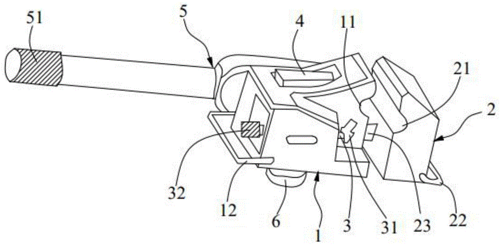
图1为本发明实施例中剥线钳的装配示意图;Fig. 1 is the assembly schematic diagram of wire stripper in the embodiment of the present invention;
图2为本发明实施例中剥线钳的侧视图。Fig. 2 is a side view of the wire stripper in the embodiment of the present invention.
附图标记:Reference signs:
1、固定钳头;2、活动钳头;3、进刀螺杆;4、验电器;5、手柄;6、固定旋钮;1. Fixed clamp head; 2. Movable clamp head; 3. Feed screw; 4. Electroscope; 5. Handle; 6. Fixed knob;
11、第一弧形容纳槽;111、第一绝缘保护层;12、第一拉环;11. The first arc-shaped receiving groove; 111. The first insulating protection layer; 12. The first pull ring;
21、第二弧形容纳槽;211、第二绝缘保护层;22、第二拉环;23、滑轨;21. The second arc-shaped accommodation groove; 211. The second insulating protection layer; 22. The second pull ring; 23. The slide rail;
31、刀片;32、进刀旋钮;51、防滑结构。31. blade; 32. feed knob; 51. anti-slip structure.
具体实施方式Detailed ways
为使本发明实施例的目的、技术方案和优点更加清楚,下面将结合本发明实施例中的附图,对本发明实施例中的技术方案进行清楚、完整地描述,显然,所描述的实施例是本发明一部分实施例,而不是全部的实施例。通常在此处附图中描述和示出的本发明实施例的组件可以以各种不同的配置来布置和设计。In order to make the purpose, technical solutions and advantages of the embodiments of the present invention clearer, the technical solutions in the embodiments of the present invention will be clearly and completely described below in conjunction with the drawings in the embodiments of the present invention. Obviously, the described embodiments It is a part of embodiments of the present invention, but not all embodiments. The components of the embodiments of the invention generally described and illustrated in the figures herein may be arranged and designed in a variety of different configurations.
因此,以下对在附图中提供的本发明的实施例的详细描述并非旨在限制要求保护的本发明的范围,而是仅仅表示本发明的选定实施例。基于本发明中的实施例,本领域普通技术人员在没有作出创造性劳动前提下所获得的所有其他实施例,都属于本发明保护的范围。Accordingly, the following detailed description of the embodiments of the invention provided in the accompanying drawings is not intended to limit the scope of the claimed invention, but merely represents selected embodiments of the invention. Based on the embodiments of the present invention, all other embodiments obtained by persons of ordinary skill in the art without creative efforts fall within the protection scope of the present invention.
应注意到:相似的标号和字母在下面的附图中表示类似项,因此,一旦某一项在一个附图中被定义,则在随后的附图中不需要对其进行进一步定义和解释。It should be noted that like numerals and letters denote similar items in the following figures, therefore, once an item is defined in one figure, it does not require further definition and explanation in subsequent figures.
在本发明的描述中,需要说明的是,术语“上”、“下”、“左”、“右”、“竖直”、“水平”、“内”、“外”等指示的方位或位置关系为基于附图所示的方位或位置关系,或者是该发明产品使用时惯常摆放的方位或位置关系,仅是为了便于描述本发明和简化描述,而不是指示或暗示所指的装置或元件必须具有特定的方位、以特定的方位构造和操作,因此不能理解为对本发明的限制。此外,术语“第一”、“第二”、“第三”等仅用于区分描述,而不能理解为指示或暗示相对重要性。在本发明的描述中,除非另有说明,“多个”的含义是两个或两个以上。In the description of the present invention, it should be noted that the terms "upper", "lower", "left", "right", "vertical", "horizontal", "inner", "outer" etc. The positional relationship is based on the orientation or positional relationship shown in the drawings, or the orientation or positional relationship that is usually placed when the product of the invention is used, and is only for the convenience of describing the present invention and simplifying the description, rather than indicating or implying the referred device Or elements must have a certain orientation, be constructed and operate in a certain orientation, and thus should not be construed as limiting the invention. In addition, the terms "first", "second", "third", etc. are only used for distinguishing descriptions, and should not be construed as indicating or implying relative importance. In the description of the present invention, unless otherwise specified, "plurality" means two or more.
在本发明的描述中,还需要说明的是,除非另有明确的规定和限定,术语“设置”、“连接”应做广义理解,例如,可以是固定连接,也可以是可拆卸连接,或一体地连接;可以是机械连接,也可以是电连接。对于本领域的普通技术人员而言,可以具体情况理解上述术语在本发明中的具体含义。In the description of the present invention, it should also be noted that, unless otherwise clearly specified and limited, the terms "setting" and "connection" should be understood in a broad sense, for example, it can be a fixed connection or a detachable connection, or Connected integrally; either mechanically or electrically. Those of ordinary skill in the art can understand the specific meanings of the above terms in the present invention in specific situations.
在本发明中,除非另有明确的规定和限定,第一特征在第二特征之“上”或之“下”可以包括第一和第二特征直接接触,也可以包括第一和第二特征不是直接接触而是通过它们之间的另外的特征接触。而且,第一特征在第二特征“之上”、“上方”和“上面”包括第一特征在第二特征正上方和斜上方,或仅仅表示第一特征水平高度高于第二特征。第一特征在第二特征“之下”、“下方”和“下面”包括第一特征在第二特征正下方和斜下方,或仅仅表示第一特征水平高度小于第二特征。In the present invention, unless otherwise clearly specified and limited, a first feature being "on" or "under" a second feature may include direct contact between the first and second features, and may also include the first and second features Not in direct contact but through another characteristic contact between them. Moreover, "above", "above" and "above" the first feature on the second feature include that the first feature is directly above and obliquely above the second feature, or simply means that the first feature is horizontally higher than the second feature. "Below", "beneath" and "under" the first feature to the second feature include that the first feature is directly below and obliquely below the second feature, or simply means that the first feature has a lower level than the second feature.
下面详细描述本发明的实施例,所述实施例的示例在附图中示出,其中自始至终相同或类似的标号表示相同或类似的元件或具有相同或类似功能的元件。下面通过参考附图描述的实施例是示例性的,仅用于解释本发明,而不能理解为对本发明的限制。Embodiments of the present invention are described in detail below, examples of which are shown in the drawings, wherein the same or similar reference numerals designate the same or similar elements or elements having the same or similar functions throughout. The embodiments described below by referring to the figures are exemplary only for explaining the present invention and should not be construed as limiting the present invention.
为了便于在狭小空间内对导线绝缘层进行剥削,提高接线效率,缩短停电时间,保护人员安全,本实施例提供一种剥线钳,以下结合图1至图2对本实施例的具体内容进行详细描述。In order to facilitate the stripping of the wire insulation layer in a small space, improve the wiring efficiency, shorten the power outage time, and protect the safety of personnel, this embodiment provides a wire stripper. The specific content of this embodiment will be described in detail below in conjunction with Fig. 1 to Fig. 2 describe.
实施例一Embodiment one
如图1所示,本实施例的剥线钳包括固定钳头1、活动钳头2、进刀螺杆3和验电器4。As shown in FIG. 1 , the wire stripper of this embodiment includes a fixed pliers head 1 , a
其中,固定钳头1一端设置有第一弧形容纳槽11。活动钳头2与固定钳头1之间能够相对伸缩,活动钳头2靠近固定钳头1一端设置有第二弧形容纳槽21,第一弧形容纳槽11与第二弧形容纳槽21对应设置。进刀螺杆3转动设置于固定钳头1并伸出,进刀螺杆3伸向活动钳头2的一端设置有刀片31。验电器4设置于固定钳头1,用于检测周围环境是否带电。Wherein, one end of the fixed pliers head 1 is provided with a first arc-shaped receiving
简而言之,本发明所提供的剥线钳,剥线钳的固定钳头1与活动钳头2能够相对伸缩,固定钳头1设置有第一弧形容纳槽11,活动钳头2设置有第二弧形容纳槽21,第一弧形容纳槽11和第二弧形容纳槽21之间用于固定卡接导线,设置有刀片31的进刀螺杆3转动设置在固定钳头1上,通过旋转进刀螺杆3可以调节刀片31的进刀深度,便于在狭小空间内对导线绝缘层进行剥削,提高接线效率,缩短停电时间;验电器4用来检测电力线路是否带电,并发出报警信号提醒作业人员,保护人员安全。In short, in the wire stripper provided by the present invention, the fixed pincer head 1 and the
进一步地,剥线钳还包括手柄5,手柄5的一端与固定钳头1可拆卸连接。手柄5采用高强度绝缘材料制成,提高使用安全性,适用于电力生产带电作业要求。Further, the wire stripper also includes a
具体地,固定钳头1上设置有中空型套筒,手柄5穿设在中空型套筒内并能够在中空型套筒内沿中空型套筒的轴线来回前后滑动。Specifically, the fixed pliers head 1 is provided with a hollow sleeve, and the
示例性地,步骤一:工人手持手柄5的第一端,手柄5的第二端插入中空型套筒内,手柄5带动固定钳头1旋转180度;步骤二:推动手柄5继续插入中空型套筒,且使手柄5的第二端伸出中空型套筒,手柄5的第一端插入中空型套筒内,步骤三:工人手持手柄5的第二端进行继续转动。Exemplarily, Step 1: The worker holds the first end of the
更进一步地,手柄5与固定钳头1的连接处设置有棘轮棘爪机构。手柄5带动固定钳头1只能单向旋转。减小操作范围且省力。在其他实施例中,手柄5还可以带动固定钳头1360度旋转,适用电力线路的各种工作场所。Furthermore, a ratchet and pawl mechanism is provided at the joint between the
进一步地,手柄5远离固定钳头1的一端设置有防滑结构51。防滑结构51可以是防滑纹和防滑凸起等。Further, an
进一步地,剥线钳还包括第一拉环12和第二拉环22,第一拉环12设置于固定钳头1远离活动钳头2的一侧,第二拉环22设置于活动钳头2远离固定钳头1的一侧。通过手拉剥线钳两侧的第一拉环12和第二拉环22,使活动钳头2相对固定钳头1张开。Further, the wire stripper also includes a
进一步地,进刀螺杆3远离刀片31的一端设置有进刀旋钮32,进刀旋钮32外表面设置有防滑纹。通过用手旋拧进刀旋钮32,改变刀片31的进刀深度,满足环切多种厚度的导线绝缘层。Further, a
进一步地,如图1和图2所示,活动钳头2的一端固设有滑轨23,固定钳头1内设有滑槽,滑轨23插设于滑槽内并能够在滑槽中滑动。Further, as shown in Fig. 1 and Fig. 2, one end of the
进一步地,还包括固定旋钮6,固定钳头1开设有螺纹长孔,螺纹长孔沿垂直于滑槽的方向延伸并与滑槽连通,滑轨23上开设有多个定位孔,固定旋钮6螺接于螺纹长孔并能够穿过滑槽插设于任一定位孔内。当确定好固定钳头1与活动钳头2之间的间距后,通过旋拧固定旋钮6,增加固定旋钮6拧入固定钳头1的深度,进一步使固定旋钮6插到滑轨23的定位孔内,限制活动钳头2的活动,保证导线被环切时,导线可以牢固的夹在活动钳头2和固定钳头1之间。Further, it also includes a fixed
实施例二Embodiment two
本实施例提供了一种剥线钳,与实施例一相比,本实施例提供的剥线钳的基本结构与实施例一相同,仅第一弧形容纳槽11和第二弧形容纳槽21的设置存在差异,本实施例不再对与实施例一相同的结构进行赘述。This embodiment provides a wire stripper. Compared with Embodiment 1, the basic structure of the wire stripper provided by this embodiment is the same as Embodiment 1, only the first arc-shaped
进一步地,如图2所示,第一弧形容纳槽11内设置有第一绝缘保护层111,第二弧形容纳槽21内设置有第二绝缘保护层211。当固定钳头1和活动钳头2与导线接触时,通过增设第一绝缘保护层111和第二绝缘保护层211,保证固定钳头1和活动钳头2具有良好的绝缘性,保证使用安全性。Further, as shown in FIG. 2 , a first insulating
进一步地,第一绝缘保护层111和第二绝缘保护层211的外表面均设置有防滑凸点。增大导线与第一绝缘保护层111和第二绝缘保护层211的接触摩擦力,防止剥线钳环切导线时发生滑动。Further, the outer surfaces of the first
注意,上述仅为本发明的较佳实施例及所运用技术原理。本领域技术人员会理解,本发明不限于这里所说的特定实施例,对本领域技术人员来说能够进行各种明显的变化、重新调整和替代而不会脱离本发明的保护范围。因此,虽然通过以上实施例对本发明进行了较为详细的说明,但是本发明不仅仅限于以上实施例,在不脱离本发明构思的情况下,还可以包括更多其他等效实施例,而本发明的范围由所附的权利要求范围决定。Note that the above are only preferred embodiments of the present invention and applied technical principles. Those skilled in the art will understand that the present invention is not limited to the specific embodiments described here, and various obvious changes, readjustments and substitutions can be made by those skilled in the art without departing from the protection scope of the present invention. Therefore, although the present invention has been described in detail through the above embodiments, the present invention is not limited to the above embodiments, and can also include more other equivalent embodiments without departing from the concept of the present invention, and the present invention The scope is determined by the scope of the appended claims.
Claims (8)
Priority Applications (1)
| Application Number | Priority Date | Filing Date | Title |
|---|---|---|---|
| CN202111120967.XA CN113852015B (en) | 2021-09-24 | 2021-09-24 | Wire stripper |
Applications Claiming Priority (1)
| Application Number | Priority Date | Filing Date | Title |
|---|---|---|---|
| CN202111120967.XA CN113852015B (en) | 2021-09-24 | 2021-09-24 | Wire stripper |
Publications (2)
| Publication Number | Publication Date |
|---|---|
| CN113852015A CN113852015A (en) | 2021-12-28 |
| CN113852015B true CN113852015B (en) | 2023-04-07 |
Family
ID=78979702
Family Applications (1)
| Application Number | Title | Priority Date | Filing Date |
|---|---|---|---|
| CN202111120967.XA Active CN113852015B (en) | 2021-09-24 | 2021-09-24 | Wire stripper |
Country Status (1)
| Country | Link |
|---|---|
| CN (1) | CN113852015B (en) |
Citations (5)
| Publication number | Priority date | Publication date | Assignee | Title |
|---|---|---|---|---|
| CN102842868A (en) * | 2012-09-06 | 2012-12-26 | 安徽省电力公司滁州供电公司 | Method for fastening lead damper bolt in electrified way |
| CN204886006U (en) * | 2015-08-26 | 2015-12-16 | 国网新疆电力公司疆南供电公司 | A ratchet spanner for high tension transmission line |
| CN106826683A (en) * | 2017-03-09 | 2017-06-13 | 国网河北省电力公司衡水供电分公司 | Electrification fastening device |
| CN108493851A (en) * | 2018-06-19 | 2018-09-04 | 佛山市达普光机电科技有限公司 | A kind of dielectric glass layer equipment of power cable |
| CN112038985A (en) * | 2020-09-03 | 2020-12-04 | 广东电网有限责任公司梅州供电局 | Cable T-shaped head dismounting device |
Family Cites Families (4)
| Publication number | Priority date | Publication date | Assignee | Title |
|---|---|---|---|---|
| CN201355749Y (en) * | 2008-12-30 | 2009-12-02 | 上海市南电力工程有限公司 | Insulated pole with double-clip wire clamp for distribution lines |
| CN104319695A (en) * | 2014-10-15 | 2015-01-28 | 苏州速腾电子科技有限公司 | Wire stripper for cable |
| CN104518460B (en) * | 2014-12-26 | 2017-02-08 | 国家电网公司 | Winder for binding cable binding wire |
| CN107800071B (en) * | 2015-12-11 | 2020-06-02 | 青岛恒科瑞新信息科技有限公司 | Hydraulic pliers |
-
2021
- 2021-09-24 CN CN202111120967.XA patent/CN113852015B/en active Active
Patent Citations (5)
| Publication number | Priority date | Publication date | Assignee | Title |
|---|---|---|---|---|
| CN102842868A (en) * | 2012-09-06 | 2012-12-26 | 安徽省电力公司滁州供电公司 | Method for fastening lead damper bolt in electrified way |
| CN204886006U (en) * | 2015-08-26 | 2015-12-16 | 国网新疆电力公司疆南供电公司 | A ratchet spanner for high tension transmission line |
| CN106826683A (en) * | 2017-03-09 | 2017-06-13 | 国网河北省电力公司衡水供电分公司 | Electrification fastening device |
| CN108493851A (en) * | 2018-06-19 | 2018-09-04 | 佛山市达普光机电科技有限公司 | A kind of dielectric glass layer equipment of power cable |
| CN112038985A (en) * | 2020-09-03 | 2020-12-04 | 广东电网有限责任公司梅州供电局 | Cable T-shaped head dismounting device |
Also Published As
| Publication number | Publication date |
|---|---|
| CN113852015A (en) | 2021-12-28 |
Similar Documents
| Publication | Publication Date | Title |
|---|---|---|
| CN104253398B (en) | Insulated conductor apparatus for peeling off | |
| TWM521831U (en) | Multi-function wire stripping hand tool and kit | |
| CN203445546U (en) | Wire stripping tool for electrician | |
| CN204144824U (en) | Insulating bar suspended insulated guide wire peeler | |
| CN104134952A (en) | Insulated overhead wire stripper for insulating rod | |
| CN214013709U (en) | Insulating layer stripping knife for cable | |
| CN116169611B (en) | Cable cut-off peeling device | |
| CN205610099U (en) | Control cable oversheath stripper | |
| CN106451252A (en) | Cable stripping device | |
| CN204615291U (en) | A kind of adjusting insulation wire wire stripping pliers | |
| CN201685197U (en) | Manual tongs for shearing and clamping | |
| CN203434541U (en) | Safe secondary cable stripping device | |
| CN113852015A (en) | a wire stripper | |
| CN215240272U (en) | Insulating clamp for cable | |
| CN107650037A (en) | A kind of insulation diagonal cutting pliers to light | |
| CN211183169U (en) | A straight peeling pliers | |
| CN212399285U (en) | Integrative pincers of trimming wire stripping | |
| CN211743651U (en) | Insulation layer stripping tool set for 10kV to 20kV insulated conductor | |
| CN208142737U (en) | A kind of wire stripper | |
| CN203339462U (en) | Wire stripper | |
| CN113681476A (en) | Multifunctional bolt clipper structure based on communication | |
| CN109347008B (en) | A power cable stripping device | |
| CN220762296U (en) | Electrician pliers with branching function | |
| CN104734078B (en) | Wire stripper | |
| CN222127485U (en) | Multifunctional wire stripper with hooks |
Legal Events
| Date | Code | Title | Description |
|---|---|---|---|
| PB01 | Publication | ||
| PB01 | Publication | ||
| SE01 | Entry into force of request for substantive examination | ||
| SE01 | Entry into force of request for substantive examination | ||
| GR01 | Patent grant | ||
| GR01 | Patent grant | ||
| CB03 | Change of inventor or designer information | ||
| CB03 | Change of inventor or designer information |
Inventor after: Luo Riteng Inventor after: Lan Zhengpeng Inventor after: Zhou Yuhui Inventor after: Chen Dingping Inventor after: Lai Hualan Inventor after: Zhang Wenyuan Inventor after: Ling Lin Inventor after: Chen Hui Inventor after: Zhong Jianda Inventor after: Tan Qingxian Inventor after: Zhang Zhihua Inventor after: Li Weiquan Inventor before: Luo Riteng Inventor before: Lan Zhengpeng Inventor before: Zhou Huanghui Inventor before: Chen Dingping Inventor before: Lai Hualan Inventor before: Zhang Wenyuan Inventor before: Ling Lin Inventor before: Chen Hui Inventor before: Zhong Jianda Inventor before: Tan Qingxian Inventor before: Zhang Zhihua Inventor before: Li Weiquan |