CN113834302A - Multi-angle stirring type drying device for flame retardant and using method - Google Patents

Multi-angle stirring type drying device for flame retardant and using method Download PDF

Info

Publication number
CN113834302A
CN113834302A CN202111234335.6A CN202111234335A CN113834302A CN 113834302 A CN113834302 A CN 113834302A CN 202111234335 A CN202111234335 A CN 202111234335A CN 113834302 A CN113834302 A CN 113834302A
Authority
CN
China
Prior art keywords
stirring
mixture
inner cavity
placing
bull stick
Prior art date
Legal status (The legal status is an assumption and is not a legal conclusion. Google has not performed a legal analysis and makes no representation as to the accuracy of the status listed.)
Pending
Application number
CN202111234335.6A
Other languages
Chinese (zh)
Inventor
唐小强
于建华
Current Assignee (The listed assignees may be inaccurate. Google has not performed a legal analysis and makes no representation or warranty as to the accuracy of the list.)
Jiangsu Zhuofeng New Material Technology Co ltd
Original Assignee
Jiangsu Zhuofeng New Material Technology Co ltd
Priority date (The priority date is an assumption and is not a legal conclusion. Google has not performed a legal analysis and makes no representation as to the accuracy of the date listed.)
Filing date
Publication date
Application filed by Jiangsu Zhuofeng New Material Technology Co ltd filed Critical Jiangsu Zhuofeng New Material Technology Co ltd
Priority to CN202111234335.6A priority Critical patent/CN113834302A/en
Publication of CN113834302A publication Critical patent/CN113834302A/en
Pending legal-status Critical Current

Links

Images

Classifications

    • F—MECHANICAL ENGINEERING; LIGHTING; HEATING; WEAPONS; BLASTING
    • F26—DRYING
    • F26B—DRYING SOLID MATERIALS OR OBJECTS BY REMOVING LIQUID THEREFROM
    • F26B11/00—Machines or apparatus for drying solid materials or objects with movement which is non-progressive
    • F26B11/12—Machines or apparatus for drying solid materials or objects with movement which is non-progressive in stationary drums or other mainly-closed receptacles with moving stirring devices
    • F26B11/14—Machines or apparatus for drying solid materials or objects with movement which is non-progressive in stationary drums or other mainly-closed receptacles with moving stirring devices the stirring device moving in a horizontal or slightly-inclined plane
    • F—MECHANICAL ENGINEERING; LIGHTING; HEATING; WEAPONS; BLASTING
    • F26—DRYING
    • F26B—DRYING SOLID MATERIALS OR OBJECTS BY REMOVING LIQUID THEREFROM
    • F26B21/00—Arrangements for supplying or controlling air or other gases for drying solid materials or objects
    • F26B21/001—Air generating units, e.g. movable or independent of drying enclosure
    • F—MECHANICAL ENGINEERING; LIGHTING; HEATING; WEAPONS; BLASTING
    • F26—DRYING
    • F26B—DRYING SOLID MATERIALS OR OBJECTS BY REMOVING LIQUID THEREFROM
    • F26B21/00—Arrangements for supplying or controlling air or other gases for drying solid materials or objects
    • F26B21/003—Air or gas filters
    • F—MECHANICAL ENGINEERING; LIGHTING; HEATING; WEAPONS; BLASTING
    • F26—DRYING
    • F26B—DRYING SOLID MATERIALS OR OBJECTS BY REMOVING LIQUID THEREFROM
    • F26B21/00—Arrangements for supplying or controlling air or other gases for drying solid materials or objects
    • F26B21/50—Ducting arrangements from the source of air or other gases to the materials or objects being dried
    • F—MECHANICAL ENGINEERING; LIGHTING; HEATING; WEAPONS; BLASTING
    • F26—DRYING
    • F26B—DRYING SOLID MATERIALS OR OBJECTS BY REMOVING LIQUID THEREFROM
    • F26B25/00—Details of general application not covered by group F26B21/00 or F26B23/00
    • F26B25/001—Handling, e.g. loading or unloading arrangements
    • F26B25/002—Handling, e.g. loading or unloading arrangements for bulk goods
    • F—MECHANICAL ENGINEERING; LIGHTING; HEATING; WEAPONS; BLASTING
    • F26—DRYING
    • F26B—DRYING SOLID MATERIALS OR OBJECTS BY REMOVING LIQUID THEREFROM
    • F26B25/00—Details of general application not covered by group F26B21/00 or F26B23/00
    • F26B25/02—Applications of driving mechanisms, not covered by another subclass
    • F—MECHANICAL ENGINEERING; LIGHTING; HEATING; WEAPONS; BLASTING
    • F26—DRYING
    • F26B—DRYING SOLID MATERIALS OR OBJECTS BY REMOVING LIQUID THEREFROM
    • F26B25/00—Details of general application not covered by group F26B21/00 or F26B23/00
    • F26B25/04—Agitating, stirring, or scraping devices
    • F—MECHANICAL ENGINEERING; LIGHTING; HEATING; WEAPONS; BLASTING
    • F26—DRYING
    • F26B—DRYING SOLID MATERIALS OR OBJECTS BY REMOVING LIQUID THEREFROM
    • F26B25/00—Details of general application not covered by group F26B21/00 or F26B23/00
    • F26B25/06—Chambers, containers, or receptacles
    • F26B25/08—Parts thereof
    • F26B25/12—Walls or sides; Doors

Landscapes

  • Engineering & Computer Science (AREA)
  • Mechanical Engineering (AREA)
  • General Engineering & Computer Science (AREA)
  • Drying Of Solid Materials (AREA)

Abstract

本发明公开了一种阻燃剂用多角度搅拌式烘干装置及使用方法,包括放置单元,所述放置单元包括放置箱,所述放置箱的底部设置有搅拌单元,所述搅拌单元包括运作箱,所述运作箱内腔底部的右侧固定连接有电机。本发明通过电机、第一转杆、皮带轮、传动皮带、第二转杆、搅拌杆的配合,从而对混合料进行横向均匀搅拌,同时通过搅拌杆转动时产生的离心力带动搅拌轮进行纵向旋转,从而对混合料进行纵向均匀搅拌,通过风机将外界空气传输至传输管的内腔,通过加热器对传输管内腔的空气进行加热,空气加热后传输至分流管和喷气嘴的内腔,最后通过喷气嘴将热空气吹送至混合料,从而对混合料进行加热烘干。

Figure 202111234335

The invention discloses a multi-angle stirring drying device for flame retardants and a method of using the same. A motor is fixedly connected to the right side of the bottom of the inner cavity of the operation box. The invention uses the cooperation of the motor, the first rotating rod, the pulley, the transmission belt, the second rotating rod and the stirring rod, so that the mixed material is uniformly stirred horizontally, and the stirring wheel is driven to rotate longitudinally by the centrifugal force generated when the stirring rod rotates. Therefore, the mixture is uniformly stirred longitudinally, and the external air is transmitted to the inner cavity of the transmission pipe by the fan, and the air in the inner cavity of the transmission pipe is heated by the heater. The air nozzle blows hot air to the mixture to heat and dry the mixture.

Figure 202111234335

Description

Multi-angle stirring type drying device for flame retardant and using method
Technical Field
The invention relates to the technical field of flame retardant processing, in particular to a multi-angle stirring type drying device for a flame retardant and a using method.
Background
The flame retardant is a functional assistant for endowing inflammable polymers with flame resistance, is mainly designed aiming at the flame resistance of high polymer materials, has various types, is divided into an additive flame retardant and a reactive flame retardant according to a using method, exerts the flame retardant effect through a plurality of mechanisms, is mainly applied to the fields of transportation, electronic and electrical equipment, furniture and building materials, is an application of a flame retardant technology in actual life, is a special chemical assistant for improving the combustion performance of inflammable and inflammable materials, is widely applied to the flame retardant processing of various decoration materials, can effectively prevent, delay or stop the propagation of flame when being attacked by an external fire source so as to achieve the flame retardant effect, fully stirs a mixture in a high-temperature dry environment during processing of the flame retardant, and avoids caking caused by stirring, and then need use agitating unit, but flame retardant agitating unit on the market only has single (mixing) shaft stirring when using, easily causes upper and lower floor's mixture uneven, and does not possess stoving heating function when the stirring to the mixture easily meets cold caking when the stirring, thereby has reduced the purity and the quality of flame retardant, therefore we have proposed a multi-angle stirring formula drying device and application method for the flame retardant, solve this problem.
Disclosure of Invention
The invention aims to provide a multi-angle stirring type drying device for a flame retardant and a using method thereof, which have the advantages of uniformly stirring a mixture in multiple angles and conveniently heating and drying the mixture, and solve the problems that when a flame retardant stirring device in the market is used, the mixture of an upper layer and a lower layer is not uniform due to the fact that only a single stirring shaft is used for stirring, and the mixture is not provided with a drying and heating function during stirring, so that the mixture is easy to be cooled and agglomerated during stirring, and the purity and the quality of the flame retardant are reduced.
In order to achieve the purpose, the invention provides the following technical scheme: a multi-angle stirring type drying device for flame retardants comprises a placing unit, wherein the placing unit comprises a placing box, a stirring unit is arranged at the bottom of the placing box, the stirring unit comprises an operating box, a motor is fixedly connected to the right side of the bottom of an inner cavity of the operating box, a second rotating rod is movably connected to the left side of the bottom of the inner cavity of the operating box through a bearing, a first rotating rod is fixedly connected to an output shaft of the motor, the other ends of the second rotating rod and the first rotating rod penetrate through the placing box and extend to the inner cavity of the placing box, belt pulleys are fixedly connected to the surfaces of the second rotating rod and the first rotating rod at one end of the inner cavity of the operating box, a transmission belt is connected between the two belt pulleys, a stirring rod is fixedly connected to the surfaces of the second rotating rod and the first rotating rod at one end of the inner cavity of the placing box, and a stirring wheel is movably connected to one end of the stirring rod, which is far away from the first rotating rod and the second rotating rod, through a bearing, the drying device is characterized in that a drying unit is arranged at the top of the placing box and comprises a protection box, a fan is arranged in an inner cavity of the protection box, a transmission pipe is communicated with the bottom of the fan, the bottom of the transmission pipe penetrates through the placing box and extends to the inner cavity of the placing box, the transmission pipe is communicated with a flow dividing pipe, a heater is arranged on the surface of one end, located at the inner cavity of the placing box, of the transmission pipe, and an air nozzle is communicated with the bottom of the flow dividing pipe.
Preferably, the both sides of placing roof portion all communicate with the feeder hopper, the top swing joint of feeder hopper has the shield.
Preferably, both sides of the placing box are communicated with a material discharging pipe, and the surface of the material discharging pipe is provided with an electromagnetic valve.
Preferably, the ventilation groove has all been seted up to the both sides of placing the roof portion, the first dustproof filter screen of inner chamber fixedly connected with in ventilation groove.
Preferably, the front surface of the placing box is provided with a visual window, and the visual window is made of transparent tempered glass.
Preferably, the periphery of the bottom of the inner cavity of the placing box is fixedly connected with supporting blocks, and the bottoms of the supporting blocks are fixedly connected with the flow dividing pipes.
Preferably, the ventilation hole has all been seted up to the both sides at protection box top, the dustproof filter screen of inner chamber fixedly connected with second in ventilation hole.
Preferably, the using method comprises the following steps:
A. firstly, by opening a sealing cover, the mixture is transmitted to an inner cavity of a placing box through a feed hopper;
B. then, by starting a motor, an output shaft of the motor drives a first rotating rod to start rotating, the first rotating rod drives a belt pulley to rotate while rotating, the belt pulley drives a belt pulley on the other side to rotate while rotating, the belt pulley drives a second rotating rod to rotate while rotating, the first rotating rod and the second rotating rod drive a stirring rod to rotate while rotating, the stirring rod is used for transversely and rotatably stirring the mixture in the inner cavity of the placing box, the stirring wheel is driven to rotate by centrifugal force generated by the stirring rod during rotation, the stirring wheel is used for driving the mixture in the inner cavity of the placing box to longitudinally and rotatably stir, and the stirring condition of the inner cavity of the placing box is monitored in real time through a visual window, so that the mixture is uniformly stirred, and the caking condition of the mixture is avoided;
C. the method comprises the following steps that a fan is started, the fan absorbs external air through a vent hole and transmits the external air to an inner cavity of a transmission pipe, a heater is started to carry out heat treatment on the air in the inner cavity of the transmission pipe, the air after heat treatment is transmitted to an inner cavity of a shunt pipe, the hot air is shunted and transmitted to an inner cavity of an air nozzle through the shunt pipe, the air nozzle is stably supported through a supporting block, the air nozzle is prevented from falling off, then the hot air is uniformly sprayed on mixed materials through the air nozzle to be heated and dried, meanwhile, the ventilation of the inner cavity of a placing box is accelerated through a ventilation groove, the drying efficiency is improved, the mixed materials are heated and dried, and the condition that the mixed materials meet cold blocks is avoided;
D. and finally, opening the electromagnetic valve, and discharging the mixed and dried mixture through a discharge pipe.
Compared with the prior art, the invention has the following beneficial effects:
1. the invention drives the first rotating rod to rotate through the output shaft of the motor, the first rotating rod drives the belt pulley at the other side and the second rotating rod to rotate through the belt pulley and the transmission belt, the stirring rod is driven to transversely rotate through the rotation of the second rotating rod and the first rotating rod, so that the mixture is transversely and uniformly stirred, meanwhile, the stirring wheel is driven to longitudinally rotate through the centrifugal force generated when the stirring rod rotates, so that the mixture is longitudinally and uniformly stirred, the outside air is transmitted to the inner cavity of the transmission pipe through the fan, the air in the inner cavity of the transmission pipe is heated through the heater, the heated air is transmitted to the inner cavities of the diversion pipe and the air nozzle, and finally, the hot air is blown to the mixture through the air nozzle, so that the mixture is heated and dried, the problem that when a flame retardant stirring device on the market is used, only a single stirring shaft is used, so that the mixture at the upper layer and the lower layer is not uniform is easily caused is solved, and the mixture does not have the drying and heating functions during stirring, so that the mixture is easy to be cooled and agglomerated during stirring, thereby reducing the purity and quality of the flame retardant.
Drawings
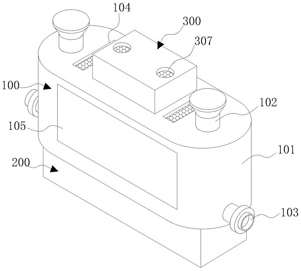
FIG. 1 is a schematic view of the overall structure of the present invention;
FIG. 2 is a schematic cross-sectional view of a stirring unit according to the present invention;
FIG. 3 is a schematic cross-sectional view of the placement box of the present invention;
FIG. 4 is an enlarged view of a portion of FIG. 3;
FIG. 5 is a schematic view of a front view of a partial cross-sectional structure of the storage box of the present invention.
In the figure: 100. a placing unit; 101. placing a box; 102. a feed hopper; 103. a discharge pipe; 104. a ventilation slot; 105. a visual window; 106. a support block; 200. a stirring unit; 201. an operation box; 202. a motor; 203. a first rotating lever; 204. a second rotating rod; 205. a belt pulley; 206. a drive belt; 207. a stirring rod; 208. a stirring wheel; 300. a drying unit; 301. a protection box; 302. a fan; 303. a conveying pipe; 304. a heater; 305. a shunt tube; 306. an air nozzle; 307. a vent hole.
Detailed Description
The technical solutions in the embodiments of the present invention will be clearly and completely described below with reference to the drawings in the embodiments of the present invention, and it is obvious that the described embodiments are only a part of the embodiments of the present invention, and not all of the embodiments. All other embodiments, which can be derived by a person skilled in the art from the embodiments given herein without making any creative effort, shall fall within the protection scope of the present invention.
The placing unit 100, the placing box 101, the feeding hopper 102, the discharging pipe 103, the ventilating slot 104, the visible window 105, the supporting block 106, the stirring unit 200, the operation box 201, the motor 202, the first rotating rod 203, the second rotating rod 204, the belt pulley 205, the driving belt 206, the stirring rod 207, the stirring wheel 208, the drying unit 300, the protection box 301, the fan 302, the conveying pipe 303, the heater 304, the shunt pipe 305, the air nozzle 306 and the ventilating hole 307 of the present invention are all common standard components or components known by those skilled in the art, and the structure and principle thereof can be known by technical manuals or by routine experimental methods.
Referring to fig. 1-5, a multi-angle stirring type drying device for flame retardant comprises a placing unit 100, the placing unit 100 comprises a placing box 101, a stirring unit 200 is arranged at the bottom of the placing box 101, the stirring unit 200 comprises an operating box 201, a motor 202 is fixedly connected to the right side of the bottom of the inner cavity of the operating box 201, a second rotating rod 204 is movably connected to the left side of the bottom of the inner cavity of the operating box 201 through a bearing, a first rotating rod 203 is fixedly connected to an output shaft of the motor 202, the other ends of the second rotating rod 204 and the first rotating rod 203 penetrate through the placing box 101 and extend to the inner cavity of the placing box 101, belt pulleys 205 are fixedly connected to the surfaces of the second rotating rod 204 and the first rotating rod 203 at one end of the inner cavity of the operating box 201, a transmission belt 206 is connected between the two belt pulleys 205, a stirring rod 207 is fixedly connected to the surfaces of the second rotating rod 204 and the first rotating rod 203 at one end of the inner cavity of the placing box 101, one end of the stirring rod 207, which is far away from the first rotating rod 203 and the second rotating rod 204, is movably connected with a stirring wheel 208 through a bearing, the top of the placing box 101 is provided with a drying unit 300, the drying unit 300 comprises a protective box 301, an inner cavity of the protective box 301 is provided with a fan 302, the bottom of the fan 302 is communicated with a transmission pipe 303, the bottom of the transmission pipe 303 penetrates through the placing box 101 and extends to the inner cavity of the placing box 101 and is communicated with a diversion pipe 305, the surface of the transmission pipe 303, which is positioned at one end of the inner cavity of the placing box 101, is provided with a heater 304, the bottom of the diversion pipe 305 is communicated with an air nozzle 306, the first rotating rod 203 is driven to rotate through an output shaft of the motor 202, the first rotating rod 203 drives the other side belt pulley 205 and the second rotating rod 204 to rotate through a belt pulley 205 and a transmission belt 206, the stirring rod 207 is driven to transversely rotate through the rotation of the second rotating rod 204 and the first rotating rod 203, so as to transversely and uniformly stir the mixture, simultaneously, centrifugal force that produces when rotating through puddler 207 drives stirring wheel 208 and carries out longitudinal rotation, thereby carry out vertical even stirring to the mixture, transmit outside air to the inner chamber of transmission pipe 303 through fan 302, heat the air of transmission pipe 303 inner chamber through heater 304, transmit to the inner chamber of shunt tubes 305 and air nozzle 306 after the air heating, blow hot-air to the mixture through air nozzle 306 at last, thereby heat the stoving to the mixture, flame retardant agitating unit on the market is when using, only there is single (mixing) shaft stirring, it is inhomogeneous easily to cause upper and lower layer mixture, and do not possess the stoving heating function when the stirring, so that the mixture easily meets cold junction when the stirring, thereby the problem of flame retardant purity and quality has been reduced.
Specifically, the both sides of placing case 101 top all communicate there is feeder hopper 102, and the top swing joint of feeder hopper 102 has the shield, and through setting up feeder hopper 102, played the convenience and transmitted the mixture that will stir and dry to the effect of placing case 101 inner chamber, through setting up the shield, played convenient dirt-proof effect, avoid the dust to enter into to the inner chamber of placing case 101 through feeder hopper 102 to can reduce the condition of mixture quality.
Specifically, the both sides of placing case 101 all communicate and have row material pipe 103, arrange the surface of material pipe 103 and be provided with the solenoid valve, arrange material pipe 103 through setting up, played the convenient mixture after will mixing the stoving from placing case 101 inner chamber exhaust effect, through setting up the solenoid valve, played the effect of conveniently opening or closing row material pipe 103.
Specifically, place the both sides at case 101 top and all seted up ventilation groove 104, the first dustproof filter screen of inner chamber fixedly connected with of ventilation groove 104 through setting up ventilation groove 104, has played the effect to placing case 101 inner chamber quick ventilation, makes and places case 101 inner chamber circulation of air to the drying efficiency of mixture has been improved, through setting up first dustproof filter screen, has played dirt-proof effect, avoids the dust to get into the inner chamber of placing case 101 through ventilation groove 104.
Specifically, the front surface of placing case 101 is provided with visual window 105, and visual window 105 is made for transparent tempered glass, through setting up visual window 105, has played the effect that makes things convenient for real-time supervision to place the stirring condition of case 101 inner chamber.
Specifically, place all around equal fixedly connected with supporting shoe 106 of case 101 inner chamber bottom, the bottom and shunt tubes 305 fixed connection of supporting shoe 106 have played the effect to shunt tubes 305 steady support through setting up supporting shoe 106, avoid shunt tubes 305 the condition that drops to appear.
Specifically, ventilation hole 307 has all been seted up to the both sides at guard box 301 top, and the dustproof filter screen of inner chamber fixedly connected with second of ventilation hole 307 through setting up ventilation hole 307, has played the effect of ventilating the inner chamber of guard box 301, through setting up the dustproof filter screen of second, has played dirt-proof effect, avoids the dust to get into the condition of guard box 301 inner chamber through ventilation hole 307.
Specifically, the using method comprises the following steps:
A. firstly, by opening a sealing cover, the mixture is conveyed to an inner cavity of a placing box 101 through a feed hopper 102;
B. then, by turning on the motor 202, the output shaft of the motor 202 drives the first rotating rod 203 to start rotating, the first rotating rod 203 drives the belt pulley 205 to rotate while rotating, the belt pulley 205 drives the belt pulley 205 on the other side to rotate while rotating through the transmission belt 206, the second rotating rod 204 is driven to rotate by the rotation of the belt pulley 205 on the other side, the stirring rod 207 is driven to rotate by the rotation of the first rotating rod 203 and the second rotating rod 204, the mixture in the inner cavity of the placing box 101 is transversely rotated and stirred by the stirring rod 207, the centrifugal force generated by the stirring rod 207 when rotating drives the stirring wheel 208 to rotate, the mixture in the inner cavity of the placing box 101 is driven by the stirring wheel 208 to carry out longitudinal rotation stirring, through the visual window 105, the stirring condition of the inner cavity of the placing box 101 is monitored in real time, so that the mixture is uniformly stirred, and the caking condition of the mixture is avoided;
C. next, by turning on the fan 302, the fan 302 sucks and transmits external air to the inner cavity of the transmission pipe 303 through the vent hole 307, by turning on the heater 304, the heater 304 carries out heat treatment on the air in the inner cavity of the transmission pipe 303, the heat-treated air is transmitted to the inner cavity of the shunt pipe 305, the shunt pipe 305 shunts and transmits the hot air to the inner cavity of the air nozzle 306, the air nozzle 306 is stably supported through the supporting block 106, the air nozzle 306 is prevented from falling off, then the hot air is uniformly sprayed on the mixture through the air nozzle 306 for heating and drying, meanwhile, the ventilation of the inner cavity of the placing box 101 is accelerated through the ventilation groove 104, the drying efficiency is improved, so that the mixture is heated and dried, and the condition that the mixture is cooled and blocked is avoided;
D. and finally, opening the electromagnetic valve, and discharging the mixed and dried mixture through a discharge pipe 103.
When the device is used, the electric elements are started through an external controller, firstly, the sealing cover is opened, and the mixture is transmitted to the inner cavity of the placing box 101 through the feed hopper 102; then, by turning on the motor 202, the output shaft of the motor 202 drives the first rotating rod 203 to start rotating, the first rotating rod 203 drives the belt pulley 205 to rotate while rotating, the belt pulley 205 drives the belt pulley 205 on the other side to rotate while rotating through the transmission belt 206, the second rotating rod 204 is driven to rotate by the rotation of the belt pulley 205 on the other side, the stirring rod 207 is driven to rotate by the rotation of the first rotating rod 203 and the second rotating rod 204, the mixture in the inner cavity of the placing box 101 is transversely rotated and stirred by the stirring rod 207, the centrifugal force generated by the stirring rod 207 when rotating drives the stirring wheel 208 to rotate, the mixture in the inner cavity of the placing box 101 is driven by the stirring wheel 208 to carry out longitudinal rotation stirring, through the visual window 105, the stirring condition of the inner cavity of the placing box 101 is monitored in real time, so that the mixture is uniformly stirred, and the caking condition of the mixture is avoided; next, by turning on the fan 302, the fan 302 sucks and transmits external air to the inner cavity of the transmission pipe 303 through the vent hole 307, by turning on the heater 304, the heater 304 carries out heat treatment on the air in the inner cavity of the transmission pipe 303, the heat-treated air is transmitted to the inner cavity of the shunt pipe 305, the shunt pipe 305 shunts and transmits the hot air to the inner cavity of the air nozzle 306, the air nozzle 306 is stably supported through the supporting block 106, the air nozzle 306 is prevented from falling off, then the hot air is uniformly sprayed on the mixture through the air nozzle 306 for heating and drying, meanwhile, the ventilation of the inner cavity of the placing box 101 is accelerated through the ventilation groove 104, the drying efficiency is improved, so that the mixture is heated and dried, and the condition that the mixture is cooled and blocked is avoided; at last, by opening the electromagnetic valve, the mixture after mixing and drying is discharged through the discharge pipe 103, so that the problem that the mixture is easy to encounter cold blocks when being stirred and the flame retardant purity and quality are reduced because only a single stirring shaft is used for stirring the mixture of the upper layer and the lower layer of the mixture without the drying and heating functions when being stirred is solved.
The standard parts used in the present application document can be purchased from the market, and can be customized according to the description of the specification and the accompanying drawings, the specific connection mode of each part adopts the conventional means of mature bolt, rivet, welding and the like in the prior art, the machines, parts and equipment adopt the conventional models in the prior art, the control mode is automatically controlled by a controller, the control circuit of the controller can be realized by simple programming of technicians in the field, the control circuit belongs to the common knowledge in the field, and the present application document is mainly used for protecting mechanical devices, so the control mode and the circuit connection are not explained in detail in the present application.
It is noted that, herein, relational terms such as first and second, and the like may be used solely to distinguish one entity or action from another entity or action without necessarily requiring or implying any actual such relationship or order between such entities or actions. Also, the terms "comprises," "comprising," or any other variation thereof, are intended to cover a non-exclusive inclusion, such that a process, method, article, or apparatus that comprises a list of elements does not include only those elements but may include other elements not expressly listed or inherent to such process, method, article, or apparatus. Without further limitation, an element defined by the phrase "comprising an … …" does not exclude the presence of other identical elements in a process, method, article, or apparatus that comprises the element.
Although embodiments of the present invention have been shown and described, it will be appreciated by those skilled in the art that changes, modifications, substitutions and alterations can be made in these embodiments without departing from the principles and spirit of the invention, the scope of which is defined in the appended claims and their equivalents.

Claims (8)

1. The utility model provides a multi-angle stirring formula drying device for fire retardant, is including placing unit (100), its characterized in that: place unit (100) including placing case (101), the bottom of placing case (101) is provided with stirring unit (200), stirring unit (200) is including operation case (201), right side fixedly connected with motor (202) of operation case (201) inner chamber bottom, there is second bull stick (204) left side of operation case (201) inner chamber bottom through bearing swing joint, the first bull stick (203) of output shaft fixedly connected with of motor (202), the other end of second bull stick (204) and first bull stick (203) runs through places case (101) and extends to the inner chamber of placing case (101), the equal fixedly connected with belt pulley (205) in surface that second bull stick (204) and first bull stick (203) are located operation case (201) inner chamber one end, and the transmission is connected with driving belt (206) between two belt pulleys (205), second bull stick (204) and first bull stick (203) are located the surface fixedly connected with of placing case (101) inner chamber one end and are connected with belt (206), second bull stick (204) and first bull stick (203) are located the surface fixedly connected with of placing case (101) inner chamber one end Puddler (207), the one end that puddler (207) kept away from first bull stick (203) and second bull stick (204) has stirring wheel (208) through bearing swing joint, the top of placing case (101) is provided with stoving unit (300), stoving unit (300) are including guard box (301), the inner chamber of guard box (301) is provided with fan (302), the bottom intercommunication of fan (302) has transmission pipe (303), the bottom of transmission pipe (303) is run through and is placed case (101) and extend to the inner chamber of placing case (101) and communicate and have shunt tubes (305), transmission pipe (303) are located the surface of placing case (101) inner chamber one end and are provided with heater (304), the bottom intercommunication of shunt tubes (305) has air nozzle (306).
2. The multi-angle stirring type drying device for the flame retardant according to claim 1, characterized in that: the both sides of placing case (101) top all communicate with feed hopper (102), the top swing joint of feed hopper (102) has the shield.
3. The multi-angle stirring type drying device for the flame retardant according to claim 1, characterized in that: both sides of the placing box (101) are communicated with a material discharging pipe (103), and the surface of the material discharging pipe (103) is provided with an electromagnetic valve.
4. The multi-angle stirring type drying device for the flame retardant according to claim 1, characterized in that: place the both sides at case (101) top and all seted up ventilation groove (104), the first dustproof filter screen of inner chamber fixedly connected with in ventilation groove (104).
5. The multi-angle stirring type drying device for the flame retardant according to claim 1, characterized in that: the front surface of the placing box (101) is provided with a visual window (105), and the visual window (105) is made of transparent tempered glass.
6. The multi-angle stirring type drying device for the flame retardant according to claim 1, characterized in that: the periphery of the bottom of the inner cavity of the placing box (101) is fixedly connected with supporting blocks (106), and the bottom of each supporting block (106) is fixedly connected with a shunt pipe (305).
7. The multi-angle stirring type drying device for the flame retardant according to claim 1, characterized in that: vent hole (307) have all been seted up to the both sides at guard box (301) top, the dustproof filter screen of inner chamber fixedly connected with second of vent hole (307).
8. The use method of the multi-angle stirring type drying device for the flame retardant according to any one of claims 1 to 7, is characterized in that: the using method comprises the following steps:
A. firstly, by opening a sealing cover, the mixture is conveyed to an inner cavity of a placing box (101) through a feed hopper (102);
B. then, by starting the motor (202), an output shaft of the motor (202) drives the first rotating rod (203) to start rotating, the first rotating rod (203) drives the belt pulley (205) to rotate while rotating, the belt pulley (205) drives the belt pulley (205) on the other side to rotate while rotating through the transmission belt (206), the belt pulley (205) on the other side drives the second rotating rod (204) to rotate while rotating, the first rotating rod (203) and the second rotating rod (204) drive the stirring rod (207) to rotate simultaneously, the stirring rod (207) is used for transversely and rotatably stirring the mixture in the inner cavity of the placing box (101), the centrifugal force generated by the stirring rod (207) during rotation drives the stirring wheel (208) to rotate, the stirring wheel (208) is used for longitudinally and rotatably stirring the mixture in the inner cavity of the placing box (101), and the mixture passes through the visual window (105), the stirring condition of the inner cavity of the placing box (101) is monitored in real time, so that the mixture is uniformly stirred, and the caking condition of the mixture is avoided;
C. then, by turning on the blower (302), the blower (302) sucks and transmits the external air to the inner cavity of the transmission pipe (303) through the vent hole (307), the heater (304) carries out heat treatment on the air in the inner cavity of the transmission pipe (303) by turning on the heater (304), the heat-treated air is transmitted to the inner cavity of the shunt pipe (305), the hot air is transmitted to the inner cavity of the air nozzle (306) in a shunting way through a shunt pipe (305), the air nozzle (306) is stably supported by the supporting block (106) to avoid the air nozzle (306) from falling off, then hot air is uniformly sprayed on the mixture through an air nozzle (306) to be heated and dried, meanwhile, the ventilation of the inner cavity of the placing box (101) is accelerated through the ventilation groove (104), so that the drying efficiency is improved, the heating and drying treatment of the mixture is completed, and the condition that the mixture is blocked when being cooled is avoided;
D. and finally, opening the electromagnetic valve, and discharging the mixed and dried mixture through a discharge pipe (103).
CN202111234335.6A 2021-10-22 2021-10-22 Multi-angle stirring type drying device for flame retardant and using method Pending CN113834302A (en)

Priority Applications (1)

Application Number Priority Date Filing Date Title
CN202111234335.6A CN113834302A (en) 2021-10-22 2021-10-22 Multi-angle stirring type drying device for flame retardant and using method

Applications Claiming Priority (1)

Application Number Priority Date Filing Date Title
CN202111234335.6A CN113834302A (en) 2021-10-22 2021-10-22 Multi-angle stirring type drying device for flame retardant and using method

Publications (1)

Publication Number Publication Date
CN113834302A true CN113834302A (en) 2021-12-24

Family

ID=78965933

Family Applications (1)

Application Number Title Priority Date Filing Date
CN202111234335.6A Pending CN113834302A (en) 2021-10-22 2021-10-22 Multi-angle stirring type drying device for flame retardant and using method

Country Status (1)

Country Link
CN (1) CN113834302A (en)

Cited By (1)

* Cited by examiner, † Cited by third party
Publication number Priority date Publication date Assignee Title
CN118216782A (en) * 2024-05-24 2024-06-21 南通通容电子有限公司 A moisture-proof display cabinet for selling electronic components

Citations (15)

* Cited by examiner, † Cited by third party
Publication number Priority date Publication date Assignee Title
JP2000329467A (en) * 1999-05-21 2000-11-30 Taikisha Ltd Dryer
JP2005337631A (en) * 2004-05-28 2005-12-08 Kyoritsu Kogyo Kk Drying device, and drying method of dried object
CN204329503U (en) * 2014-11-11 2015-05-13 黄山市春宜米业有限公司 Rice dries knot screen
CN206073617U (en) * 2016-08-30 2017-04-05 李婧怡 A kind of twin-tub agricultural crops drying unit
CN206911206U (en) * 2017-05-03 2018-01-23 河北晟凯新材料科技有限公司 A kind of reactive flame retardant prepares and uses multi-angle stirring-type drying unit
CN207006778U (en) * 2017-08-02 2018-02-13 山东日兴新材料股份有限公司 A kind of drying machine for fire retardant
CN107940942A (en) * 2017-10-24 2018-04-20 房立洲 A kind of corn processing drying equipment easy to feeding
CN108955165A (en) * 2018-07-03 2018-12-07 南京拉艾夫医药科技有限公司 A kind of tower drier of levocarnitine production of raw medicine technique
CN109364808A (en) * 2018-12-25 2019-02-22 苏州市铭将意电子科技有限公司 A kind of comprehensive agitating device and stirring means of industrial production solution
CN209042953U (en) * 2018-11-09 2019-06-28 淮安大华生物科技有限公司 A kind of microbial manure dehydration equipment
CN210625218U (en) * 2019-08-22 2020-05-26 吉林省世伟科技开发有限公司 A kind of drying equipment for agricultural production
CN210862062U (en) * 2019-10-23 2020-06-26 河北盛益肥业有限公司 A kind of low temperature stirring drying device of sodium sulfate
CN211147173U (en) * 2019-10-12 2020-07-31 李平 Dry dehumidification agitating unit is used in building engineering construction
CN211580740U (en) * 2019-12-05 2020-09-29 湖州云宇科技服务有限公司 Integrated device for dehumidifying, drying and crushing pasture
CN214199524U (en) * 2020-11-27 2021-09-14 晨光生物科技集团克拉玛依有限公司 A stirring and drying integrated device

Patent Citations (15)

* Cited by examiner, † Cited by third party
Publication number Priority date Publication date Assignee Title
JP2000329467A (en) * 1999-05-21 2000-11-30 Taikisha Ltd Dryer
JP2005337631A (en) * 2004-05-28 2005-12-08 Kyoritsu Kogyo Kk Drying device, and drying method of dried object
CN204329503U (en) * 2014-11-11 2015-05-13 黄山市春宜米业有限公司 Rice dries knot screen
CN206073617U (en) * 2016-08-30 2017-04-05 李婧怡 A kind of twin-tub agricultural crops drying unit
CN206911206U (en) * 2017-05-03 2018-01-23 河北晟凯新材料科技有限公司 A kind of reactive flame retardant prepares and uses multi-angle stirring-type drying unit
CN207006778U (en) * 2017-08-02 2018-02-13 山东日兴新材料股份有限公司 A kind of drying machine for fire retardant
CN107940942A (en) * 2017-10-24 2018-04-20 房立洲 A kind of corn processing drying equipment easy to feeding
CN108955165A (en) * 2018-07-03 2018-12-07 南京拉艾夫医药科技有限公司 A kind of tower drier of levocarnitine production of raw medicine technique
CN209042953U (en) * 2018-11-09 2019-06-28 淮安大华生物科技有限公司 A kind of microbial manure dehydration equipment
CN109364808A (en) * 2018-12-25 2019-02-22 苏州市铭将意电子科技有限公司 A kind of comprehensive agitating device and stirring means of industrial production solution
CN210625218U (en) * 2019-08-22 2020-05-26 吉林省世伟科技开发有限公司 A kind of drying equipment for agricultural production
CN211147173U (en) * 2019-10-12 2020-07-31 李平 Dry dehumidification agitating unit is used in building engineering construction
CN210862062U (en) * 2019-10-23 2020-06-26 河北盛益肥业有限公司 A kind of low temperature stirring drying device of sodium sulfate
CN211580740U (en) * 2019-12-05 2020-09-29 湖州云宇科技服务有限公司 Integrated device for dehumidifying, drying and crushing pasture
CN214199524U (en) * 2020-11-27 2021-09-14 晨光生物科技集团克拉玛依有限公司 A stirring and drying integrated device

Cited By (2)

* Cited by examiner, † Cited by third party
Publication number Priority date Publication date Assignee Title
CN118216782A (en) * 2024-05-24 2024-06-21 南通通容电子有限公司 A moisture-proof display cabinet for selling electronic components
CN118216782B (en) * 2024-05-24 2024-09-13 南通通容电子有限公司 A moisture-proof display cabinet for selling electronic components

Similar Documents

Publication Publication Date Title
CN105444555B (en) A kind of dryer
CN207231096U (en) A kind of electric drying oven with forced convection
CN109282585B (en) A horizontal ball mill type material drying mechanical equipment
CN206730904U (en) A kind of medicine mixing arrangement
CN105104459B (en) A kind of crawler type Pizza baking box
CN210180088U (en) A kind of circulating drying equipment for Chinese medicinal materials
CN213931917U (en) Drying device is used in production of solid wood panel
CN111926164B (en) Biomass electricity dual-energy heat treatment furnace
CN213020857U (en) Vertical dryer with automatic feeding mechanism
CN105032676B (en) A kind of paint roller of wooden toy
CN218530641U (en) A hot machine that mixes for fire retardant production
CN210512523U (en) Material drying device for production of notebook plastic shell
CN210268037U (en) Drying equipment is used in chinese-medicinal material processing
CN218600174U (en) Drying equipment is used in drier processing
CN208872019U (en) A kind of Chinese medicinal granule drying equipment
CN201801516U (en) Ground automatic stubble-airing machine
CN206230707U (en) One kind can lower the temperature wood moulding mixing arrangement
CN212826205U (en) Mixing device for producing novel polymer packaging material
CN210203201U (en) An automatic fumigation furnace
CN210862131U (en) Multistage drying equipment for calcium carbonate production
CN223165856U (en) Fire retardant drying device
CN209141193U (en) A kind of microwave drier for PBT plastic pellet
CN223532755U (en) Plastic granules mixing arrangement is used in plastic flooring production
CN223741162U (en) A drying equipment for processing feed for bullfrog farming
CN224202067U (en) Drying equipment is used in quartz sand production

Legal Events

Date Code Title Description
PB01 Publication
PB01 Publication
SE01 Entry into force of request for substantive examination
RJ01 Rejection of invention patent application after publication

Application publication date: 20211224

RJ01 Rejection of invention patent application after publication