Power supply distribution equipment cable installation equipment with protection function
Technical Field
The invention relates to the technical field of cable installation equipment, in particular to power supply and distribution equipment cable installation equipment with a protection function.
Background
General cable of power supply distribution equipment when the wiring is more, when breaking down, because the quantity of cable is too much and inconvenient people maintain, general people all need look for the cable through tearing the cable in addition, but will lead to the not hard up condition to appear in the wiring when tearing to the bad contact condition appears after the equipment maintenance, do not have the effect of buffering protection, it is comparatively inconvenient.
Disclosure of Invention
Based on the technical problems in the background art, the invention provides power supply and distribution equipment cable installation equipment with a protection function.
The invention provides power supply and distribution equipment cable installation equipment with a protection function, which comprises two limiting support plates, wherein installation sliding blocks are connected to the limiting support plates in a sliding mode, fixing mechanisms are detachably installed on the installation sliding blocks, and buffering parts are installed on the installation sliding blocks along the sliding direction of the installation sliding blocks.
Preferably, a limiting sliding groove in sliding fit with the mounting sliding block penetrates through the limiting support plate, and the mounting sliding block is mounted.
Preferably, the buffer piece comprises two buffer springs, and the two buffer springs are located in the limiting sliding grooves and are respectively located on two sides of the sliding block.
Preferably, the fixing mechanism comprises a clamping mechanism, a fixing plate, a mounting column and a nut; the mounting column is connected to the fixing plate, penetrates through the mounting sliding block and is in threaded connection with the nut, and the clamping mechanism is mounted on the fixing plate.
Preferably, the clamping mechanism comprises an L-shaped limiting frame, a threaded column and a pressing block; the one end of the L-shaped limiting frame is connected on the fixed plate, a clamping groove with a single-side opening is formed between the L-shaped limiting frame and the fixed plate, the thread of the thread column penetrates through the L-shaped limiting frame, one end, close to the fixed plate, of the thread column is rotatably connected with the pressing block, one side, close to the fixed plate, of the pressing block is connected with a first anti-slip pad, and one side, close to the pressing block, of the fixed plate is connected with a second anti-slip pad.
Preferably, the clamping mechanism further comprises a limit stop lever; the limiting stop lever is rotatably connected to one side, close to the L-shaped limiting frame, of the fixing plate through a rotating shaft, the limiting stop lever can block an opening of the clamping groove, and a torsion spring is sleeved on the rotating shaft of the limiting stop lever.
Preferably, the two limiting support plates are arranged on the installation side plate, a gap exists between the two limiting support plates, and the installation side plate is provided with a threaded installation hole.
Preferably, the L-shaped limiting frame and the limiting stop lever are respectively sleeved with an insulating skin.
Preferably, a shifting lever is fixedly arranged at the top end of the limiting stop lever.
Preferably, the circumference of the top of the threaded column is provided with an anti-slip thread.
The quick disassembly check tool chuck based on D printing has the beneficial effects that: through the spacing extension board that sets up, the installation slider, fixed establishment and bolster, can carry out two segmentations with the position of cable wiring end and fix, reserve the cable of one section length between two spacing extension boards, when people overhaul, people can drag the cable, play certain buffering effect by the bolster, can stimulate the cable and make things convenient for people to overhaul, the not hard up condition appears in the wiring end in the reduction, and can slide on spacing extension board by the installation slider when meetting the cable and dragged by the mistake, and play the effect of buffering protection by the bolster, it breaks down to reduce people's cable and is dragged after the installation.
Drawings
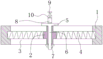
Fig. 1 is a schematic structural diagram of a power supply and distribution equipment cable installation device with a protection function according to the present invention;
fig. 2 is a cross-sectional view of a limiting support plate in a power supply and distribution equipment cable installation device with a protection function, which is provided by the invention;
fig. 3 is a schematic structural diagram of a limit stop lever in a power supply and distribution equipment cable installation device with a protection function according to the present invention;
fig. 4 is an enlarged schematic structural diagram of a in fig. 1 according to the present invention.
In the figure: 1. a limiting support plate; 2. installing a sliding block; 3. a limiting chute; 4. a buffer spring; 5. a fixing plate; 6. mounting a column; 7. a nut; 8. an L-shaped limiting frame; 9. a threaded post; 10. a compression block; 11. a limit stop lever; 12. a torsion spring; 13. and (6) installing the side plates.
Detailed Description
Referring to fig. 1 to 4, the invention provides a power supply and distribution equipment cable installation device with a protection function, which comprises two limiting support plates 1, wherein:
the limiting support plate 1 is connected with an installation slide block 2 in a sliding mode, the installation slide block 2 is detachably provided with a fixing mechanism, and the installation slide block 2 is provided with a buffer piece along the sliding direction of the installation slide block; when the cable is installed, people can clamp the cable through the fixing mechanisms on the two installation sliding blocks 2, and through the positions of the two-section type fixed cable, when people overhaul, certain buffering protection effect can be achieved when the cable is pulled, and when the cable is pulled accidentally, certain buffering protection effect can be achieved through the buffer piece.
In a specific embodiment, a limiting sliding groove 3 in sliding fit with the mounting sliding block 2 penetrates through the limiting support plate 1, and the mounting sliding block 2 is mounted; ensure that the mounting slide block 2 slides in the limiting slide groove 3.
In a specific embodiment, the buffer member comprises two buffer springs 4, and the two buffer springs 4 are both positioned in the limiting sliding groove 3 and respectively positioned at two sides of the sliding block 2; can play fine buffering protective effect by buffer spring 4, reduce the pulling to the wiring end, reduce out the condition of contact failure.
In a specific embodiment, the fixing mechanism comprises a clamping mechanism, a fixing plate 5, a mounting post 6 and a nut 7; the mounting column 6 is connected to the fixing plate 5, the mounting column 6 penetrates through the mounting sliding block 2 to be in threaded connection with the nut 7, and the clamping mechanism is mounted on the fixing plate 5; people can dismantle the cartridge on installation slider 2 with fixed plate 5 through erection column 6, by nut 7 and 6 threaded connection of erection column to people can press from both sides the cable tight in clamping mechanism to the dismouting of fixed plate 5, people can make things convenient for people to carry out the dismouting according to actual conditions, so that people carry out independent dismouting to changing the cable and overhaul, give people and provide convenient.
In a specific embodiment, the clamping mechanism comprises an L-shaped limiting frame 8, a threaded column 9 and a pressing block 10; one end of an L-shaped limiting frame 8 is connected to a fixing plate 5, a clamping groove with an opening on one side is formed between the L-shaped limiting frame 8 and the fixing plate 5, a threaded column 9 penetrates through the L-shaped limiting frame 8, one end, close to the fixing plate 5, of the threaded column 9 is rotatably connected with a pressing block 10, one side, close to the fixing plate 5, of the pressing block 10 is connected with a first anti-slip pad, one side, close to the pressing block 10, of the fixing plate 5 is connected with a second anti-slip pad, insulating skins are sleeved on the L-shaped limiting frame 8 and a limiting stop rod 11, a shift lever is fixedly arranged at the top end of the limiting stop rod 11, and anti-slip threads are arranged on the circumferential side of the top of the threaded column 9; when clamping the cable, people can block the cable into the clamping groove, people rotate the threaded column 9 again and abut against the pressing block 10 to be pressed on the cable, the cable is clamped by two non-slip mats and two non-slip mats, friction between the cable sheath can be increased, firmness of clamping the cable can be increased, a plurality of cables of the same type can be blocked into the clamping groove together, so that people can classify the cable, and people can conveniently overhaul the cable.
In a particular embodiment, the clamping mechanism further comprises a limit stop lever 11; the limiting stop lever 11 is rotatably connected to one side of the fixing plate 5 close to the L-shaped limiting frame 8 through a rotating shaft, the limiting stop lever 11 can block an opening of the clamping groove, and a torsion spring 12 is sleeved on the rotating shaft of the limiting stop lever 11; the limiting stop lever 11 can block the opening of the clamping groove, the position of the cable can be limited, the limiting stop lever 11 can be driven by the torsion spring 12 to automatically block the opening of the clamping groove, and the cable can be prevented from falling off from the opening of the clamping groove.
In a specific embodiment, two limiting support plates 1 are both mounted on a mounting side plate 13, a gap exists between the two limiting support plates 1, and a threaded mounting hole is formed in the mounting side plate 13; the whole device can be conveniently installed on the wall and other positions through the installation side plate 13, and the installation firmness of the device is ensured.
The above description is only for the preferred embodiment of the present invention, but the scope of the present invention is not limited thereto, and any person skilled in the art should be considered to be within the technical scope of the present invention, and the technical solutions and the inventive concepts thereof according to the present invention should be equivalent or changed within the scope of the present invention.