Optical system for vehicle lamp, vehicle lamp and assembly method thereof
Technical Field
The invention relates to the technical field of vehicle lamps, in particular to an optical system for a vehicle lamp, the vehicle lamp and an assembling method thereof.
Background
Nowadays, the development of the automobile industry is on a day and a new day, and the technology of the automobile lamp is also following the pace of the era. The requirements of consumers and vehicle customers for vehicle lamps are not satisfied by the regulations, and it is also desired that the vehicle lamps have more excellent optical effects and higher visibility.
In the prior art, an optical system of a vehicle lamp is generally only used for realizing optical requirements specified by laws and regulations, and the optical effect of the vehicle lamp is generally thinner, does not have a three-dimensional effect and is not high in identification degree.
Therefore, it is required to develop an optical system having more excellent optical effects, a vehicle lamp having the optical system, and an assembling method thereof.
Disclosure of Invention
In order to overcome the technical defects, the invention aims to provide an optical system with better optical effect, a vehicle lamp with the optical system and an assembling method of the optical system.
The invention discloses an optical system for a vehicle lamp, comprising: the light guide comprises a light guide bracket, a thick-wall light guide, a strip-shaped light guide and a strip-shaped light guide light source PCB;
the inner side surface of the light guide support is fixedly provided with a thick-wall light guide;
a light guide installation groove is formed in one end of the outer side surface of the light guide support along the edge, the strip light guide is installed in the light guide installation groove, and the strip light guide light source PCB is arranged at the end part of the strip light guide and is fixedly connected with the light guide support;
the outer side surface of the light guide support is a reflecting surface.
Preferably, the optical system further comprises an inner lens and a main frame;
the inner lens is fixedly arranged on the inner side of the main lining frame;
the light guide support is fixedly connected with the main lining frame, the inner lens covers the outer side surface of the light guide support, and the light incident surface of the inner lens corresponds to the opening position of the light guide mounting groove;
the light rays emitted from the strip-shaped light guide are emitted outwards through the inner lens.
Preferably, the optical system further comprises a side marker light guide, a side marker light source PCB;
a side marker light guide and a side marker light source PCB are fixedly connected with the main lining frame, and the side marker light source PCB is perpendicular to the strip light guide light source PCB;
the light emitted by the side marker light source PCB is emitted outwards through the side marker light guide and the side marker light transmission hole, so that the function of the side marker light is realized;
and light rays emitted by the strip light guide light source PCB are emitted outwards through the strip light guide and the inner lens, so that the function of a position lamp is realized.
The invention also discloses an assembling method of the optical system, the assembling method is based on the optical system, and the assembling method comprises the following steps:
welding the thick-walled light guide to the light guide support inside surface by ultrasonic welding; and the strip-shaped light guide is installed in the light guide installation groove, and the strip-shaped light guide light source PCB and the strip-shaped light guide are fixedly connected to the light guide bracket through screws.
Preferably, the optical system further comprises an inner lens and a main frame;
the assembly method further comprises the steps of:
welding the inner lens to the inner side surface of the main lining frame through laser welding;
and fixedly connecting the main lining frame with the light guide support through screws, covering the outer side surface of the light guide support by the inner lens, and enabling the light incident surface of the inner lens to correspond to the opening position of the light guide mounting groove.
Preferably, the optical system further comprises a side marker light guide and a side marker light source PCB;
the assembly method further comprises the steps of:
and fixedly connecting the side marker light guide and the side marker light source PCB with the main lining frame through hot riveting, clamping the side marker light guide between the side marker light source PCB and the main lining frame, and enabling the side marker light source PCB to be vertical to the strip-shaped light source PCB.
The invention also discloses a vehicle lamp comprising an optical system according to any one of claims 1 to 3;
the vehicle lamp further includes a turn/brake lamp unit and a thick-walled light guide light source PCB;
the turning/braking lamp unit is arranged on one side, far away from the light guide support, of the thick-wall light guide, and the thick-wall light guide light source PCB, the thick-wall light guide and the turning/braking lamp unit are fixedly connected.
Preferably, a screw groove is provided on the turn/brake lamp unit;
the thick-wall light guide light source PCB is provided with a first screw hole;
the thick-wall light guide is provided with a convex connecting part, and the connecting part is provided with a second screw hole;
and screws sequentially penetrate through the first screw holes and the second screw holes to be engaged with the screw grooves, so that the thick-wall light guide light source PCB, the thick-wall light guide and the steering/braking light unit are fixedly connected.
Preferably, the turn/brake lamp unit includes a first reflector, a first reflector light source PCB, a second reflector, and a second reflector light source PCB;
the first reflector light source PCB is fixedly connected below the first reflector, the second reflector light source PCB is fixedly connected above the second reflector, the first reflector and the second reflector are fixedly connected, and the first reflector light source PCB and the second reflector light source PCB are positioned between the first reflector and the second reflector in parallel;
the light emitted by the first reflector light source PCB is emitted outwards through the first reflector, so that the function of a steering lamp is realized; the light emitted by the second reflector light source PCB is emitted outwards through the second reflector and is used for realizing the function of a brake light; and light rays emitted by the thick-wall light guide light source PCB are emitted outwards through the thick-wall light guide for realizing the function of the position lamp.
Preferably, the thick-walled light guide light source PCB is fixedly disposed at a rear side of the reflection surfaces of the first and second reflection mirrors, the thick-walled light guide light source PCB being perpendicular to the first and second reflection mirror light source PCBs;
the thick-walled light guide light source PCB is C-shaped, and the middle part of the thick-walled light guide light source PCB is provided with an opening part for the first reflector light source PCB and the second reflector light source PCB to penetrate through.
Preferably, the vehicle lamp further includes a wire harness, a housing, and an outer cover, the wire harness is used to connect the strip-shaped light guide light source PCB, the thick-walled light guide light source PCB, the first reflector light source PCB, and the second reflector light source PCB, the housing and the outer cover are fixedly connected to form an accommodating space, and the optical system, the turn/brake light unit, and the thick-walled light guide light source PCB are fixedly disposed in the accommodating space.
The invention also discloses an assembly method of the car lamp, the assembly method is based on the car lamp, and the assembly method comprises the following steps:
welding the thick-walled light guide to the light guide support inside surface by ultrasonic welding; installing the strip-shaped light guide into the light guide installation groove, and fixedly connecting the strip-shaped light guide light source PCB and the strip-shaped light guide to the light guide bracket through screws to form the optical system;
fixedly connecting the steering/braking lamp unit, the thick-wall light guide light source PCB and the optical system through screws, wherein the steering/braking lamp unit is arranged on one side of the thick-wall light guide far away from the light guide support.
Preferably, the turn/brake lamp unit includes a first reflector, a first reflector light source PCB, a second reflector, and a second reflector light source PCB;
the assembling method comprises the following steps:
fixedly connecting the first reflector light source PCB below the first reflector through screws, and fixedly connecting the second reflector light source PCB above the second reflector through screws;
and fixedly connecting the first reflector and the second reflector through a buckle, so that the first reflector light source PCB and the second reflector light source PCB are positioned between the first reflector and the second reflector in parallel to form the steering/braking light unit.
Preferably, the step of fixedly connecting the turn/stop lamp unit, the thick-walled light guide light source PCB and the optical system by screws specifically includes:
and screws sequentially penetrate through a first screw hole formed in a thick-wall light guide light source PCB and a second screw hole formed in a connecting part formed in a thick-wall light guide to be meshed with screw grooves formed on the back sides of the reflecting surfaces of the first reflector and/or the second reflector, and the first reflector light source PCB and the second reflector light source PCB penetrate through an opening part in the middle of the C-shaped thick-wall light guide light source PCB.
Preferably, the optical system further comprises an inner lens, a main liner frame, a side marker light guide and a side marker light source PCB;
the assembly method further comprises the steps of:
welding the inner lens to the inner side surface of the main lining frame through laser welding, fixedly connecting the side marker light guide and the side marker light source PCB with the main lining frame through hot riveting, and clamping and fixing the side marker light guide between the side marker light source PCB and the main lining frame;
after the steering/stop lamp unit, the thick-walled light guide light source PCB and the optical system are fixedly connected by screws, further comprising the steps of:
and fixedly connecting the main lining frame with the light guide support through screws, so that the inner lens covers the outer side surface of the light guide support, and the light incident surface of the inner lens corresponds to the opening position of the light guide mounting groove.
Preferably, the vehicle lamp further comprises a wire harness, a housing, and an outer cover;
the assembly method further comprises the steps of:
connecting the strip-shaped light guide light source PCB, the side marker light source PCB, the thick-wall light guide light source PCB, the first reflector light source PCB and the second reflector light source PCB through a wire harness;
fixedly connecting a sub-assembly formed by fixedly connecting the steering/braking lamp unit, the thick-wall light guide light source PCB, the optical system and the wiring harness with the shell through screws;
fixedly connecting the shell and the outer mask through vibration friction welding, and enabling the sub-assembly to be accommodated in an accommodating space formed by fixedly connecting the shell and the outer mask.
After the technical scheme is adopted, compared with the prior art, the method has the following beneficial effects:
1. the optical effect can be three-dimensional, the optical effect is more excellent, and the identification degree is higher;
2. the car lamp has compact structure, occupies smaller space while realizing multiple functions, and reasonably avoids the collision between the PCB in the steering/braking lamp unit and the thick-wall light guide light source PCB;
3. aiming at the complex shape of the car lamp, various welding processes and connecting modes are adopted for assembly, and the problem that the conventional assembly means is difficult to effectively assemble is solved.
Drawings
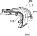
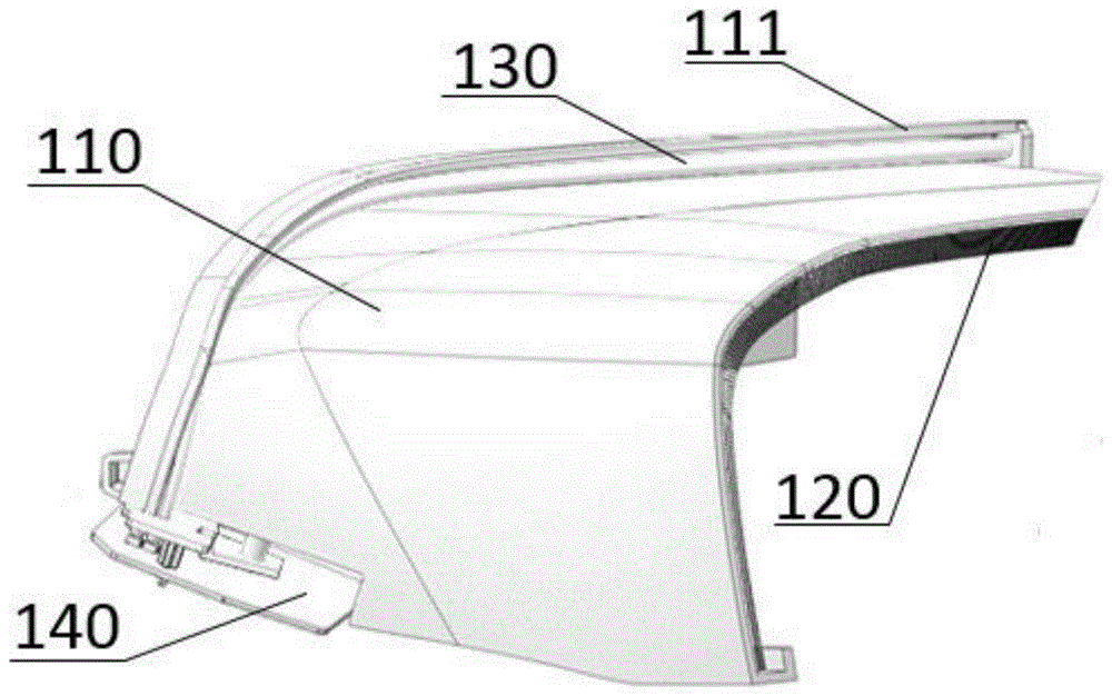
FIG. 1 is a schematic diagram of an optical system according to an embodiment of the present invention;
FIG. 2 is a schematic view of the optical system of FIG. 1 in another orientation;
FIG. 3 is an exploded view of the optical system of FIG. 1;
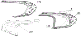
FIG. 4 is a schematic view of the inner lens and main frame when assembled;
FIG. 5 is a schematic structural view of the side marker light guide, the side marker light PCB assembled to the main bezel;
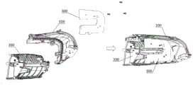
fig. 6 is a schematic structural diagram of a vehicle lamp during assembly according to an embodiment of the invention.
Fig. 7 is a schematic structural view of a turn lamp unit in the turn/brake lamp unit;
fig. 8 is a schematic structural view of a stop lamp unit in the turn/stop lamp unit;
FIG. 9 is a schematic view showing the assembled structure of the turn signal lamp unit and the stop lamp unit;
FIG. 10 is a schematic structural view of an assembly formed by a turn signal lamp unit and a stop signal lamp unit and a turn/stop signal lamp liner frame to form the turn/stop signal lamp unit;
fig. 11 is a schematic structural view of an assembly formed by the optical system, the turn/stop lamp unit, and the thick-walled light guide light source PCB in fig. 1, assembled with an assembly formed by the inner lens, the main bezel, the side marker light guide, and the side marker light source PCB;
FIG. 12 is a schematic view of the assembly of FIG. 11 with the housing;
fig. 13 is a schematic view of the assembly of fig. 12 assembled with an external mask.
Reference numerals:
100-optical system, 110-light guide holder, 111-light guide mounting groove, 120-thick walled light guide, 121-optical pattern, 122-connection portion, 130-strip light guide, 140-strip light guide light source PCB, 150-screw, 160-inner lens, 170-main liner frame, 171-side marker light transmission hole, 180-side marker light guide, 190-side marker light source PCB, 200-turn/stop light unit, 210-first reflector, 220-first reflector light source PCB, 230-screw, 240-second reflector, 250-second reflector light source PCB, 260-reflector holder, 270-screw, 280-turn/stop light liner frame, 300-thick walled light guide light source PCB, 400-housing, 500-outer cover.
a-ultrasonic welding joint, b-laser welding joint, c-hot rivet welding joint, d-buckle joint, e-buckle joint
Detailed Description
The advantages of the invention are further illustrated in the following description of specific embodiments in conjunction with the accompanying drawings.
Reference will now be made in detail to the exemplary embodiments, examples of which are illustrated in the accompanying drawings. When the following description refers to the accompanying drawings, like numbers in different drawings represent the same or similar elements unless otherwise indicated. The implementations described in the exemplary embodiments below are not intended to represent all implementations consistent with the present disclosure. Rather, they are merely examples of apparatus and methods consistent with certain aspects of the present disclosure, as detailed in the appended claims.
The terminology used in the present disclosure is for the purpose of describing particular embodiments only and is not intended to be limiting of the disclosure. As used in this disclosure and the appended claims, the singular forms "a," "an," and "the" are intended to include the plural forms as well, unless the context clearly indicates otherwise. It should also be understood that the term "and/or" as used herein refers to and encompasses any and all possible combinations of one or more of the associated listed items.
It is to be understood that although the terms first, second, third, etc. may be used herein to describe various information, such information should not be limited to these terms. These terms are only used to distinguish one type of information from another. For example, first information may also be referred to as second information, and similarly, second information may also be referred to as first information, without departing from the scope of the present disclosure. The word "if" as used herein may be interpreted as "at … …" or "when … …" or "in response to a determination", depending on the context.
In the description of the present invention, it is to be understood that the terms "longitudinal", "lateral", "upper", "lower", "front", "rear", "left", "right", "vertical", "horizontal", "top", "bottom", "inner", "outer", and the like, indicate orientations or positional relationships based on those shown in the drawings, and are used merely for convenience of description and for simplicity of description, and do not indicate or imply that the referenced devices or elements must have a particular orientation, be constructed in a particular orientation, and be operated, and thus, are not to be construed as limiting the present invention.
In the description of the present invention, unless otherwise specified and limited, it is to be noted that the terms "mounted," "connected," and "connected" are to be interpreted broadly, and may be, for example, a mechanical connection or an electrical connection, a communication between two elements, a direct connection, or an indirect connection via an intermediate medium, and specific meanings of the terms may be understood by those skilled in the art according to specific situations.
In the following description, suffixes such as "module", "component", or "unit" used to denote elements are used only for facilitating the explanation of the present invention, and have no specific meaning in themselves. Thus, "module" and "component" may be used in a mixture.
Referring to fig. 1-3, there are schematic structural diagrams of an optical system 100 for a vehicle lamp according to an embodiment of the present invention, where the optical system 100 includes: a light guide holder 110, a thick-walled light guide 120, a strip light guide 130 and a strip light guide light source PCB 140.
The thick-walled light guide 120 is fixedly arranged on the inner side surface of the light guide holder 110, in this embodiment, preferably connected by ultrasonic welding, see a in fig. 3. One end of the outer side surface of the light guide bracket 110 is provided with a light guide installation groove 111 along the edge, the strip light guide 130 is installed in the light guide installation groove 111, and the strip light guide light source PCB140 is arranged at the end of the strip light guide 130 and is fixedly connected with the light guide bracket 110, preferably, by a screw 150, and in some embodiments, may also be connected by a heat riveting or other suitable means. The outer side surface of the light guide holder 110 is a reflecting surface, and preferably, the outer side surface of the light guide holder 110 is aluminized to form the reflecting surface. In the optical system 100 of the present invention, the light emitted from the LED light source on the strip-shaped light guide PCB140 is emitted into the strip-shaped light guide 130 as a line, and then is emitted from the strip-shaped light guide 130 to the reflective surface on the outer side of the light guide bracket 110, and is emitted outward by reflection of such a large reflective surface; meanwhile, only a light source is required to be arranged on the thick-walled light guide 120, and the light source is arranged at the same end of the inner side of the light guide support 110 as the light guide mounting groove 111, so that a three-dimensional light emitting surface is formed by the light emitted by the thick-walled light guide 120 and the light reflected by the reflecting surface, and a three-dimensional optical effect is presented. Preferably, an optical pattern 121 for light distribution is disposed on the light incident surface of the thick-walled light guide 120, the optical pattern 121 may be used for collimating light, and further, an optical pattern may be disposed on the light emitting surface of the thick-walled light guide 120. The arrangement of the optical patterns on the light incident surface and/or the light emergent surface may be configured according to the optical function to be realized by the optical system 100.
Referring to fig. 4, in the present embodiment, the optical system 100 further includes an inner lens 160 and a main frame 170, and the inner lens 160 is fixedly disposed inside the main frame 170, preferably, fixedly connected by laser welding, see b in fig. 4. The light guide holder 110 is fixedly coupled to the main bezel 170, preferably, by screws. When the light guide support 110 connected with the inner lens 160 is fixedly connected with the main lining frame 170, the inner lens 160 covers the outer side surface of the light guide support 110, the light incident surface of the inner lens 160 corresponds to the opening position of the light guide mounting groove 111, the side of the inner lens 160 away from the outer side surface of the light guide support 110 is a light emergent surface, and the side of the inner lens 160 away from the light guide mounting groove 111 is also a light emergent surface. Preferably, one side of the inner lens 160 away from the light guide mounting groove 111 further includes a folded edge, the folded edge corresponds to the light exit surface of the thick-walled light guide 120, and an optical pattern for light distribution can be disposed on the folded edge. After the light emitted from the strip light guide 130 strikes the inner lens 160 with a certain wall thickness, the large surfaces (the side surfaces far from the light guide mounting groove 111 and the side surfaces far from the outer side surfaces of the light guide support 110) of the inner lens 160 are all lighted, and a three-dimensional optical effect is presented.
Referring to fig. 5, in the present embodiment, the optical system 100 further includes a side marker light guide 180 and a side marker light source PCB 190. The main lining frame 170 is provided with a side marker light transmission hole 171, the side marker light guide 180 and the side marker light source PCB190 are fixedly connected with the main lining frame 170, preferably, fixedly connected in a hot riveting manner, see a position c in fig. 5, the main lining frame 170 is provided with a hot riveting column, and the side marker light guide 180 and the side marker light source PCB190 are provided with corresponding through holes. Located inside the main backing frame 170. Preferably, the side sign light source lamp PCB is perpendicular to the strip light guide light source PCB140 to achieve sufficient utilization of space. Light emitted by the side marker light source PCB190 is emitted outward through the side marker light guide 180 and the side marker light transmission hole 171 for realizing the function of the side marker light. Preferably, the light emitted from the strip light guide light source PCB140 is emitted outward through the strip light guide 130 and the inner lens 160, so as to implement a position light function.
The assembling method of the optical system 100 of the present embodiment includes:
1) welding the thick-walled light guide 120 to the inside surface of the light guide holder 110 by ultrasonic welding; installing the strip-shaped light guide 130 into the light guide installation groove 111, and fixedly connecting the strip-shaped light guide light source PCB140 and the strip-shaped light guide 130 to the light guide bracket 110 through screws;
2) welding the inner lens 160 to the inner side of the main backing frame 170 by laser welding; fixedly connecting the main liner frame 170 with the light guide support 110 by screws, so that the inner lens 160 covers the outer side surface of the light guide support 110, and the light incident surface of the inner lens 160 corresponds to the opening position of the light guide mounting groove 111;
3) the side marker light guide 180 and the side marker light source PCB190 are fixedly connected to the main bezel 170 by hot riveting, and the side marker light guide 180 is sandwiched between the side marker light source PCB190 and the main bezel 170. Preferably, the side marker light source PCB190 is perpendicular to the strip light guide light source PCB 140.
For the above steps, in some embodiments, the inner lens 160, the side marker light guide 180, and the side marker light source PCB190 may be mounted on the main liner frame 170 in the above connection manner, and then the main liner frame 170 is fixedly connected to the light guide support 110.
Fig. 6 is a schematic structural diagram of a vehicle lamp with the optical system 100 according to an embodiment of the present invention. The lamp further includes a turn/brake lamp unit 200 and a thick-walled light guide light source PCB 300; the turn/stop lamp unit 200 is disposed at a side of the thick-walled light guide 120 away from the light guide holder 110, and the thick-walled light guide light source PCB300, the thick-walled light guide 120 and the turn/stop lamp unit 200 are fixedly connected. In this embodiment, a screw groove is formed in the steering/braking lamp unit 200, a first screw hole is formed in the thick-wall light guide light source PCB300, a protruding connecting portion 122 is formed in the thick-wall light guide 120, a second screw hole is formed in the connecting portion 122, and screws sequentially penetrate through the first screw hole and the second screw hole and are engaged with the screw groove, so that the thick-wall light guide light source PCB300, the thick-wall light guide 120 and the steering/braking lamp unit 200 are fixedly connected to form a sandwich structure. The light emitted from the thick-walled light guide light source PCB300 is emitted outward through the thick-walled light guide 120 for implementing a position light function.
Specifically, referring to fig. 7 to 10, in the present embodiment, the turn/stop lamp unit 200 includes a turn lamp unit and a stop lamp unit. Referring to fig. 7, the turn lamp unit includes a first reflector 210 and a first reflector light source PCB220, and the first reflector light source PCB220 is fixedly coupled below the first reflector 210, preferably, by a screw 230. The light emitted from the first reflector light source PCB220 is emitted outward through the first reflector 210, so as to implement the function of a turn light. Referring to fig. 8, the stop lamp unit includes a second mirror 240, a second mirror light source PCB250, and a mirror support 260. The second reflecting mirror 240 is fixedly arranged on the reflecting mirror support 260, the reflecting mirror support 260 is black, and is used for separating the reflecting surface of the second reflecting mirror 240 into a plurality of longitudinal light emitting surfaces, and a black spacing effect exists between the light emitting surfaces. Second reflector light source PCB250 is fixedly attached to second reflector 240, and second reflector light source PCB250 is preferably fixed to reflector holder 260 above second reflector 240 by screws 270 passing through holes in second reflector light source PCB250 and engaging screw grooves in reflector holder 260, wherein the positions of reflector holder 260 corresponding to the light sources on second reflector light source PCB250 are provided with through holes. The light emitted from the second reflector light source PCB250 is emitted outward through the second reflector 240 for implementing the stop lamp function. In some embodiments, the reflector holder 260 may not be provided, and the second reflector light source PCB250 may be fixedly connected to the second reflector 240 directly by screws or other suitable connection means. The first mirror light source PCB220 and the second mirror light source PCB250 are positioned in parallel between the first mirror 210 and the second mirror 240. Referring to fig. 9, the turn signal lamp unit and the stop lamp unit are fixedly connected, and in this embodiment, the first reflector 210 and the stop lamp bracket are fixedly connected by a snap, referring to d in fig. 9. In other embodiments, the first reflector 210 and the second reflector 240 of the turn signal unit and the stop signal unit may be fixedly connected by a snap or other suitable connection to form the turn/stop signal unit 200. Referring to fig. 10, in this embodiment, the turn/brake light unit 200 further includes a turn/brake light lining frame 280, the turn/brake light lining frame 280 includes a first hollow area corresponding to the turn light unit and a second hollow area corresponding to the brake light unit, a space portion is provided between the first hollow area and the second hollow area, an assembly formed by fixedly connecting the turn light unit and the brake light unit is fixedly connected to the turn/brake light lining frame 280 through a snap, see 4 in fig. 10, after the fixed connection, the space portion is located between the first reflector light source PCB220 and the second reflector light source PCB250, so as to vertically separate the two light-emitting areas, and at the same time, the structure of the entire turn/brake light unit 200 can be more stable.
Referring to fig. 6, in the present embodiment, the thick-walled light guide light source PCB300 is fixedly disposed at the back side of the reflection surfaces of the first reflector 210 and the second reflector 240, and the thick-walled light guide light source PCB300 is perpendicular to the first reflector light source PCB220 and the second reflector light source PCB250, it should be noted that perpendicular and parallel in the present application may refer to perpendicular, parallel or approximately perpendicular and parallel. The thick-walled light guide light source PCB300 is provided in a C-shape having an opening portion in the middle through which the first and second mirror light source PCBs 220 and 250 pass. Therefore, the collision of the PCB in the car lamp is effectively avoided, the structure is more compact, and the occupied space is smaller.
Referring to fig. 11 to 13, the vehicular lamp of the present embodiment further includes a wire harness (not shown) for connecting the strip-shaped light guide light source PCB140, the thick-walled light guide light source PCB300, the first reflector light source PCB220 and the second reflector light source PCB250, a housing 400 for connecting the inner PCBs of the vehicular lamp to each other and to an external control and power supply, and an outer cover 500 fixedly connected to the housing 400 and the outer cover 500, preferably, fixedly connected by vibration friction welding to form a receiving space in which the optical system 100, the turn/stop lamp unit 200 and the thick-walled light guide light source PCB300 are fixedly disposed.
The assembling method of the vehicle lamp of the embodiment includes the following steps:
1) welding the thick-walled light guide 120 to the inside surface of the light guide holder 110 by ultrasonic welding; the strip light guide 130 is mounted in the light guide mounting groove 111, and the strip light guide light source PCB140 and the strip light guide 130 are fixedly connected to the light guide bracket 110 by screws, forming a first assembly body.
2) Welding the inner lens 160 to the inner side of the main backing frame 170 by laser welding; the side marker light guide 180 and the side marker light source PCB190 are fixedly connected to the main frame 170 by hot riveting, and the side marker light guide 180 is sandwiched between the side marker light source PCB190 and the main frame 170 to form a second assembly.
3) The first mirror light source PCB220 is fixedly connected below the first mirror 210 by screws, the second mirror 240 is fixed to a mirror bracket 260 (which may be implemented by aluminizing the mirror bracket 260 in some embodiments), the second mirror light source PCB250 is fixed to the mirror bracket 260, and the first mirror 210 and the mirror bracket 260 are fixedly connected by a snap, so that the first mirror light source PCB220 and the second mirror light source PCB250 are located in parallel between the first mirror 210 and the second mirror 240. The first reflector 210, the reflector holder 260 and the turn/stop lamp bushing 280 are fixedly connected by a snap to form a turn/stop lamp unit 200, i.e., a third assembly. In other embodiments, step 3) may comprise: fixedly connecting the first reflector light source PCB220 below the first reflector 210 by screws, and fixedly connecting the second reflector light source PCB250 above the second reflector 240 by screws; the first reflector 210 and the second reflector 240 are fixedly connected by a snap, so that the first reflector light source PCB220 and the second reflector light source PCB250 are positioned between the first reflector 210 and the second reflector 240 in parallel, thereby forming the turn/stop lamp unit 200, i.e., a third assembly.
The steps 1), 2) and 3) can be carried out simultaneously or sequentially, and the sequence has no specific requirement.
4) And fixedly connecting the first assembly body, the third assembly body and the thick-wall light guide light source PCB300 through screws to form a fourth assembly body with a sandwich structure, wherein the steering/braking light unit 200 is positioned on one side of the thick-wall light guide 120 far away from the light guide support 110, and the thick-wall light guide light source PCB300 is positioned on the back side of the reflecting surface of the reflector of the steering/braking light unit 200. Specifically, screws are sequentially inserted through a first screw hole provided in the thick-walled light guide light source PCB300 and a second screw hole provided in the connecting portion 122 provided in the thick-walled light guide 120 to engage with screw grooves provided on the back side of the reflecting surface of the first reflecting mirror 210 and/or the second reflecting mirror 240, and the first reflecting mirror light source PCB220 and the second reflecting mirror light source PCB250 are inserted through an opening portion in the middle of the thick-walled light guide light source PCB300 in a C-shape to form a fourth assembly body.
5) And fixedly connecting the fourth assembly body with the second assembly body through screws to form a fifth assembly body, so that the inner lens 160 covers the outer side surface of the light guide support 110, and the light incident surface of the inner lens 160 corresponds to the opening position of the light guide mounting groove 111.
6) Connecting the PCBs in the fifth assembly body through a wire harness, fixing the fifth assembly body of the connected wire harness to the shell 400 through screws, and fixedly connecting the shell 400 and the outer cover 500 through vibration friction welding, so that the fifth assembly body of the connected wire harness is accommodated in an accommodating space formed by fixedly connecting the shell 400 and the outer cover 500, and a vehicle lamp is formed.
The technical scheme of this application, to in complicated figurative car light, multiple technologies such as laser welding, ultrasonic bonding, rivet hot welding have been applied, constitute a plurality of subassemblies, then carry out the assembly of whole lamp on next step, the problem that complicated figurative car light adopts conventional means to be difficult to the assembly has been solved, the car light structure is also compacter when realizing multiple optical function simultaneously, occupation space is less, and rationally to turning to/braking the collision of PCB in the lamp unit and thick wall light guide source effectively avoid.
It should be noted that the embodiments of the present invention have been described in terms of preferred embodiments, and not by way of limitation, and that those skilled in the art can make modifications and variations of the embodiments described above without departing from the spirit of the invention.