Multi-functional painful branch of academic or vocational study nursing is with device of releiving of pain
Technical Field
The invention belongs to the technical field of medical instruments, and particularly relates to a multifunctional pain relieving device for nursing in a pain department.
Background
After the age of 20 years, the lumbar intervertebral disc begins to degenerate, and with the increase of age, the annulus fibrosus at the back and outside of the intervertebral disc is weaker, the water content of the nucleus pulposus of the intervertebral disc is gradually reduced, the tension of the nucleus pulposus is reduced, the intervertebral disc becomes thinner, meanwhile, the content of proteoglycan in the nucleus pulposus is reduced, collagen fibers are increased, and the nucleus pulposus loses elasticity. On the basis of degenerative change of the lumbar intervertebral disc, the conditions of long-term waist fatigue, improper actions and the like are added, so that the intervertebral disc is more easily extruded and abraded, each layer of fiber of the fiber ring is mutually rubbed to generate glass sample change, and the elasticity is lost. Once the annulus fibrosus is ruptured, the intervertebral disc will be protruded, the lumbar vertebra is often pressed and pain is obvious, the pain radiates to lower limb, and the lower limb is numb and painful. The lumbar muscle strain refers to a disease mainly manifested by recurrent attacks of dull pain in the waist, aggravation after fatigue, remissions after rest, etc., is a common lumbar disease, is limited to both sides of the waist, mostly aching pain, and has a good effect in general massage.
Therefore, when the waist of the patient is nursed, the waist of the patient is massaged and massaged by medical care personnel or family members of the patient, but the massage time is long, and the trouble is caused to the medical care personnel or the family members of the patient to a certain extent; in addition, a mode of massaging the waist of the patient by a massage device to replace manual massage is provided, but the existing massage device has a single massage mode, mostly knocks the waist of the patient, has poor effect, and easily causes bad influence on the patient due to long-time knocking; the massage device who has now is mostly just knocking the massage to patient's waist when the massage, can not carry out effectual expansion to patient's lumbar vertebrae and lumbar vertebrae both sides, influences patient's recovery effect.
Disclosure of Invention
Aiming at the situation, in order to overcome the defects of the prior art, the invention provides a multifunctional pain relieving device for nursing in the pain department, and the problem that the existing massage device has poor effect of massaging the waist of a patient is effectively solved.
In order to achieve the purpose, the invention adopts the following technical scheme: a multifunctional pain relieving device for nursing in pain department comprises support legs, a seat plate is arranged on the support legs, and a backrest is connected to the seat plate; the backrest is provided with a mobile device, and the mobile device is detachably connected with a relieving device; the relieving device comprises a massage cavity detachably connected with the moving device, a middle massage structure is arranged in the massage cavity, and a pair of side massage structures which are in sliding connection with the massage cavity are arranged on two sides of the middle massage structure; the middle massage structure comprises a pair of middle massage components which are symmetrically arranged, a driving component which drives the middle massage component to move left and right while moving up and down is also arranged in the massage cavity, and the driving component drives the side massage structure to synchronously move up and down while driving the middle massage component to move up and down; the side massage structure is including supporting the chamber, supports the intracavity and rotates and be connected with rotatory chamber, supports the chamber and goes up the rigid coupling and have fixed massage subassembly, is equipped with on the rotatory chamber along the rotatory chamber rotation along the radial gliding outer massage subassembly of rotatory chamber.
Furthermore, the moving device comprises a moving motor fixedly connected with the backrest, and the output end of the moving motor is connected with a moving screw rod; the movable screw rod is connected with a movable cavity in a threaded manner, and the massage cavity is detachably connected with the movable cavity; a pair of sliding rods corresponding to the moving cavity are fixedly connected to the backrest, and the moving cavity is connected with the sliding rods in a sliding manner; the movable cavity is connected with a fastening screw in a threaded manner, the massage cavity is provided with a bolt corresponding to the fastening screw, and the movable cavity is provided with a push outlet corresponding to the massage cavity.
Furthermore, the driving component comprises a driving motor fixedly connected with the massage cavity, and the output end of the driving motor is connected with a driving bevel gear; the driving bevel gear is meshed with a middle bevel gear, the middle bevel gear is coaxially and fixedly connected with a massage screw rod, the massage screw rod is in threaded connection with a vertical driving plate which drives the middle massage assembly and the side massage structure to move up and down, and the supporting cavity is fixedly connected with the vertical driving plate.
Furthermore, a driven bevel gear is meshed with the middle bevel gear, a reciprocating crank is connected to the driven bevel gear, and a driving rack corresponding to the reciprocating crank is connected to the massage cavity in a sliding manner; the driving rack is provided with a driving slideway, and the reciprocating crank is provided with a driving shaft corresponding to the driving slideway; the massage cavity is rotatably connected with a driving gear meshed with the driving rack, and the driving gear is coaxially and fixedly connected with a bidirectional crank; two ends of the bidirectional crank are rotatably connected with connecting rods, and the other ends of the connecting rods are rotatably connected with transverse sliding blocks which are in sliding connection with the massage cavities; the transverse sliding block can drive the corresponding middle massage component to slide left and right, and the transverse sliding block and the vertical driving plate are respectively provided with a driving slideway corresponding to the middle massage component.
Furthermore, the side massage structure comprises a massage motor fixedly connected with the support cavity, the output end of the massage motor is connected with a shifting rod, a grooved wheel corresponding to the shifting rod is rotatably connected in the support cavity, and the shifting rod is coaxially and fixedly connected with a limiting disc corresponding to the grooved wheel; the grooved wheel is coaxially and fixedly connected with a driving wheel, and a rotating gear fixedly connected with the rotating cavity is meshed on the driving wheel.
Furthermore, a fixed shaft is fixedly connected to the supporting cavity and fixedly connected with the fixed massage component; a sun wheel is fixedly connected to the fixed shaft, and a planet wheel which is rotationally connected with the rotating cavity is meshed to the sun wheel; the planet wheel is coaxially and fixedly connected with a massage crank, a reciprocating rack corresponding to the massage crank is connected to the support cavity in a sliding mode, and a massage gear meshed with the reciprocating rack is connected to the support cavity in a rotating mode; the reciprocating rack is provided with a reciprocating chute corresponding to the massage crank, and the massage crank is provided with a sliding shaft matched with the reciprocating chute; the massage gear is coaxially and fixedly connected with a driving disc, and a plurality of driving rods which are rotatably connected with the outer massage assembly are rotatably connected onto the driving disc.
Furthermore, the middle massage component and the fixed massage component have the same structure, the middle massage component and the fixed massage component comprise middle massage cylinders, and supporting plates are arranged in the middle massage cylinders; the supporting plate is rotatably connected with a middle gear, the transverse sliding block is fixedly connected with a massage rack meshed with the middle gear, and the rotating cavity is fixedly connected with a gear ring meshed with the middle gear; the middle gear is meshed with a bevel gear set, the output end of the bevel gear set is connected with a contact rod, a middle crank is further rotatably connected to the middle massage cylinder, and a pin shaft matched with the contact rod is arranged on the middle crank; the middle crank is rotatably connected with a middle connecting rod, the middle connecting rod is rotatably connected with a massage rod, and the massage rod is connected with a middle massage ball; the massage ball is provided with a guide rod which is in sliding connection with the support plate, and the support plate is provided with a top spring which is matched with the massage ball.
Furthermore, the outer massage component comprises an outer massage barrel which is rotationally connected with the driving rod, the outer massage barrel is connected with a sliding plate in a sliding way, and the sliding plate is connected with a side massage ball; the outer massage barrel is rotatably connected with a spline, the spline is slidably connected with a spline barrel fixedly connected with the sliding plate, and the spline barrel is sleeved with a buffer spring.
Compared with the prior art, the invention has the following beneficial effects:
1. when the lumbar vertebra stretching massage device is used, the driving assembly drives the middle massage assembly to move up and down at the same time of moving up and down, namely, arc-shaped stretching massage from inside to outside and from outside to inside is continuously carried out on two sides of the lumbar vertebra of a patient; the side massage structure massages the waist of patient, when massaging, can strike patient's waist heart, when strikeing, by waist heart from inside to outside and outside-in through outer massage subassembly stretch out the massage to waist heart periphery, improve the effect of massage.
2. When the middle massage structure is used, the middle massage component is driven by the driving component to move up and down, left and right, and the middle massage component performs knocking massage on a patient under the action of the massage rack.
3. When the side massage structure is used and the middle massage structure does not work, the side massage structure can perform point-aligning massage on a patient; when the middle massage structure works, the vertical driving plate drives the side massage structures to move up and down to massage the patient comprehensively; the side massage structure enables the rotary cavity to intermittently rotate through the matching of the deflector rod and the grooved wheel, so that the fixed massage assembly and the outer massage assembly intermittently massage a patient, and the comfort of the patient is improved; meanwhile, when the rotary cavity rotates, the outer massage component is driven to reciprocate along the radial direction of the rotary cavity through the matching of the planet wheel, the sun wheel, the massage crank, the reciprocating rack, the massage gear, the driving disc, the driving rod and the like; namely, the outer massage component does reciprocating motion along the radial direction of the rotary cavity to massage the patient while the rotary cavity rotates; under the action of the gear ring, the fixed massage component intermittently performs knocking massage on the patient.
Drawings
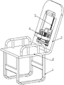
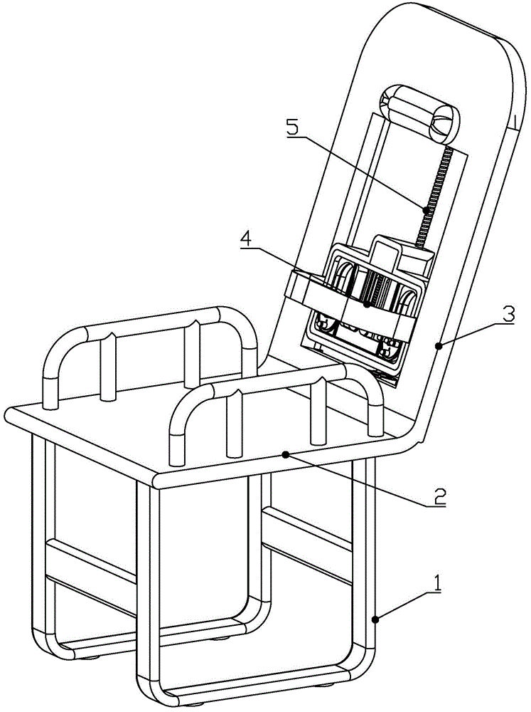
FIG. 1 is a first isometric view of the present invention;
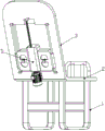
FIG. 2 is a second isometric view of the present invention;
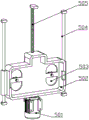
FIG. 3 is a schematic diagram of a mobile device according to the present invention;
figure 4 is a first isometric view of a soothing mechanism of the present invention;
figure 5 is a second perspective view of the soothing device of the present invention;
FIG. 6 is a schematic view of the internal structure of the soothing device of the present invention;
fig. 7 is a first isometric view of a massage structure of the present invention;
fig. 8 is a second isometric view of a medial massage structure of the present invention;
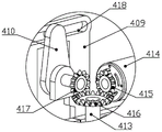
FIG. 9 is an enlarged view of area A of FIG. 8 according to the present invention;
FIG. 10 is a schematic view of a massage structure according to the present invention;
FIG. 11 is a schematic structural view of a lateral massage mechanism according to the present invention;
FIG. 12 is a schematic view showing the inner structure of the lateral massage mechanism according to the present invention;
FIG. 13 is a schematic view of a rotary assembly according to the present invention;
FIG. 14 is a first isometric view of the internal structure of the rotary cavity of the present invention;
FIG. 15 is a second isometric view of the internal structure of the rotating chamber of the present invention;
FIG. 16 is a schematic view showing the combination of the opening and closing assembly, the side massage assembly and the fixed massage assembly;
FIG. 17 is a schematic view of the internal structure of the massage assembly of the present invention;
FIG. 18 is a schematic view of the internal structure of the lateral massage assembly of the present invention;
in the figure: 1. leg, 2, seat board, 3, backrest, 4, relieving device, 401, fixing belt, 402, massage cavity, 403, side massage structure, 404, middle massage structure, 405, bolt, 406, vertical slideway, 407, vertical driving plate, 408, transverse slider, 409, driving rack, 410, reciprocating crank, 411, driving gear, 412, middle massage component, 413, massage screw rod, 414, driving motor, 415, driving bevel gear, 416, middle bevel gear, 417, driven bevel gear, 418, driving slideway, 419, massage rack, 420, connecting rod, 421, bidirectional crank, 422, outer massage component, 423, fixed massage component, 424, rotating cavity, 425, supporting cavity, 426, massage motor, 427, deflector rod, 428, grooved wheel, 429, rotating gear, 430, driving wheel, 431, limiting disc, 432, sun wheel, 433, planet wheel, 434, massage crank, 435, driving rod, 436. reciprocating rack, 437, massage gear, 438, driving disk, 439, fixed shaft, 440, gear ring, 441, middle gear, 442, bevel gear set, 443, contact rod, 444, pin shaft, 445, middle crank, 446, middle connecting rod, 447, guide rod, 448, top spring, 449, middle massage ball, 450, buffer spring, 451, slide plate, 452, side massage ball; 5. the device comprises a moving device 501, a moving motor 502, a moving cavity 503, a push-out opening 504, a sliding rod 505 and a moving screw rod.
Detailed Description
A multifunctional pain relieving device for nursing in pain department, as shown in figures 1-18, comprises support legs 1, a seat plate 2 arranged on the support legs 1, and a backrest 3 connected to the seat plate 2; the backrest 3 is provided with a mobile device 5, and the mobile device 5 is detachably connected with a relieving device 4; the relieving device 4 comprises a massage cavity 402 detachably connected with the mobile device 5, a middle massage structure 404 is arranged in the massage cavity 402, a pair of side massage structures 403 slidably connected with the massage cavity 402 are arranged on two sides of the middle massage structure 404, and a vertical slide 406 matched with the side massage structures 403 is arranged in the massage cavity 402; the massage cavity 402 is detachably connected with a fixing band 401, and the fixing band 401 is a fixing band 401 with a hook-and-loop fastener. When the massage device is used, the lumbar of a patient is massaged through the middle massage structure 404, in addition, the middle massage structure 404 can be moved to the position of the spine through the arrangement of the moving device 5, the spine of the patient is massaged, and the waist of the patient is massaged through the pair of side massage structures 403.
The middle massage structure 404 comprises a pair of middle massage components 412 which are symmetrically arranged, a driving component which drives the middle massage component 412 to move left and right while moving up and down is further arranged in the massage cavity 402, and the driving component drives the side massage structure 403 to synchronously move up and down while driving the middle massage component 412 to move up and down; the middle massage component 412 is driven by the driving component to move up and down at the same time, namely, arc-shaped stretching massage from inside to outside and from outside to inside is continuously carried out on the two sides of the lumbar of the patient; the lateral massage structure 403 comprises a supporting cavity 425, a rotating cavity 424 is rotatably connected in the supporting cavity 425, a fixed massage component 423 is fixedly connected on the supporting cavity 425, and an outer massage component 422 which rotates along with the rotating cavity 424 and slides along the radial direction of the rotating cavity 424 is arranged on the rotating cavity 424; the side massage structure 403 massages the waist of the patient, when massaging, the waist center of the patient can be knocked, and when knocking, the waist center periphery is subjected to stretching massage from inside to outside and from outside to inside through the outer massage component 422, so that the massage effect is improved.
Further, as shown in fig. 3, the moving device 5 includes a moving motor 501 fixedly connected to the backrest 3, and an output end of the moving motor 501 is connected to a moving screw 505; a moving cavity 502 is screwed on the moving screw rod 505, and the massage cavity 402 is detachably connected with the moving cavity 502; a pair of sliding rods 504 corresponding to the moving cavity 502 are fixedly connected to the backrest 3, and the moving cavity 502 is slidably connected with the sliding rods 504; the moving motor 501 is matched with the moving screw rod 505 to drive the moving cavity 502 to slide up and down along the sliding rod 504, and the massage device is driven to move up and down to effectively massage the two sides of the lumbar vertebra of the patient; a fastening screw is screwed on the movable cavity 502, a bolt 405 corresponding to the fastening screw is arranged on the massage cavity 402, and a push-out opening 503 corresponding to the massage cavity 402 is arranged on the movable cavity 502; the massage chamber 402 is fixed by a fastening screw engaged with the bolt 405, and the massage device is pushed out through the push-out opening 503.
Further, as shown in fig. 7-9, the driving assembly includes a driving motor 414 fixedly connected to the massage chamber 402, and an output end of the driving motor 414 is connected to a driving bevel gear 415; the driving bevel gear 415 is engaged with a middle bevel gear 416, the middle bevel gear 416 is coaxially and fixedly connected with a massage screw 413, the massage screw 413 is in threaded connection with a vertical driving plate 407 which drives the middle massage assembly 412 and the side massage structure 403 to move up and down, and the supporting cavity 425 is fixedly connected with the vertical driving plate 407. The driving motor 414 drives the massage screw 413 to rotate through the driving bevel gear 415 and the middle bevel gear 416, the massage screw 413 drives the vertical driving plate 407 to move up and down, and the vertical driving plate 407 drives the middle massage assembly 412 and the side massage structure 403 to synchronously move up and down to massage the lumbar vertebra and the waist of the patient in a reciprocating manner.
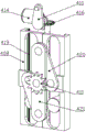
Further, as shown in fig. 8 and 9, a driven bevel gear 417 is engaged with the middle bevel gear 416, a reciprocating crank 410 is connected to the driven bevel gear 417, and a driving rack 409 corresponding to the reciprocating crank 410 is slidably connected to the massage cavity 402; the driving rack 409 is provided with a driving slideway 418, and the reciprocating crank 410 is provided with a driving shaft corresponding to the driving slideway 418; the middle bevel gear 416 drives the reciprocating crank 410 to rotate through the driven bevel gear 417, and the reciprocating crank 410 is matched with the driving slide 418 on the driving rack 409 through the driving shaft to drive the driving rack 409 to slide along the massage cavity 402;
the massage cavity 402 is rotatably connected with a driving gear 411 engaged with the driving rack 409, the driving gear 411 is coaxially and fixedly connected with a bidirectional crank 421, and the middle part of the bidirectional crank 421 is coaxially and fixedly connected with the driving gear 411; both ends of the bidirectional crank 421 are rotatably connected with a connecting rod 420, and the other end of the connecting rod 420 is rotatably connected with a transverse sliding block 408 which is slidably connected with the massage cavity 402; the transverse sliding block 408 can drive the corresponding middle massage component 412 to slide left and right, and the transverse sliding block 408 and the vertical driving plate 407 are respectively provided with a driving slide 418 corresponding to the middle massage component 412; the driving rack 409 is meshed with the driving gear 411 to drive the bidirectional crank 421 to rotate, and the bidirectional crank 421 drives the transverse sliding block 408 to slide left and right through the connecting rod 420; the horizontal sliding block 408 and the vertical driving plate 407 cooperate to drive the middle massage component 412 to move left and right while moving up and down, i.e. to continuously perform arc-shaped stretching massage from inside to outside and from outside to inside on both sides of the lumbar vertebra of the patient.
Further, as shown in fig. 11-13, the side massage structure 403 includes a massage motor 426 fixedly connected to the support cavity 425, an output end of the massage motor 426 is connected to a shift rod 427, a grooved wheel 428 corresponding to the shift rod 427 is rotatably connected to the support cavity 425, and a limiting plate 431 corresponding to the grooved wheel 428 is coaxially and fixedly connected to the shift rod 427; the grooved wheel 428 is coaxially and fixedly connected with a driving wheel 430, and a rotating gear 429 fixedly connected with the rotating cavity 424 is meshed with the driving wheel 430; the massage motor 426, the shift lever 427, the grooved pulley 428, the driving wheel 430 and the rotary gear 429 are matched to drive the rotary cavity 424 to intermittently rotate.
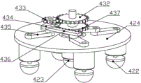
Further, as shown in fig. 14-16, a fixed shaft 439 is fixedly connected to the supporting cavity 425, and the fixed shaft 439 is fixedly connected to the fixed massage component 423; a sun wheel 432 is fixedly connected to the fixed shaft 439, a planet wheel 433 which is rotatably connected with the rotating cavity 424 is meshed to the sun wheel 432, and the planet wheel 433 is driven to rotate along the sun wheel 432 when the rotating cavity 424 rotates; a massage crank 434 is coaxially and fixedly connected to the planet wheel 433, a reciprocating rack 436 corresponding to the massage crank 434 is slidably connected to the support cavity 425, and a massage gear 437 meshed with the reciprocating rack 436 is rotatably connected to the support cavity 425; the planet wheel 433 drives the reciprocating rack 436 to slide along the supporting cavity 425 in a reciprocating manner through the massage crank 434, and the reciprocating rack 436 drives the massage gear 437 to rotate; the reciprocating rack 436 is provided with a reciprocating chute corresponding to the massage crank 434, and the massage crank 434 is provided with a sliding shaft matched with the reciprocating chute; the massage gears 437 are coaxially and fixedly connected with a driving disc 438, and the driving disc 438 is rotatably connected with a plurality of driving rods 435 rotatably connected with the outer massage component 422; the massage gear 437 is engaged with the driving rod 435 via the driving disk 438 to drive the outer massage component 422 to reciprocate along the radial direction of the rotating cavity 424.
Further, as shown in fig. 17, the middle massage component 412 and the fixed massage component 423 have the same structure, and both the middle massage component 412 and the fixed massage component 423 include a middle massage cylinder, and a support plate is arranged in the middle massage cylinder; a middle gear 441 is rotatably connected to the supporting plate, a massage rack 419 meshed with the middle gear 441 is fixedly connected to the transverse sliding block 408, and a gear ring 440 meshed with the middle gear 441 is fixedly connected to the rotating cavity 424; when the rotating cavity 424 rotates, the gear ring 440 drives the middle gear 441 to rotate, and when the middle massage component 412 moves up and down, the middle gear 441 rotates under the action of the massage rack 419.
The middle gear 441 is engaged with a bevel gear group 442, the output end of the bevel gear group 442 is connected with a contact rod 443, the middle massage cylinder is also rotatably connected with a middle crank 445, and the middle crank 445 is provided with a pin 444 matched with the contact rod 443; the middle crank 445 is rotatably connected with a middle connecting rod 446, the middle connecting rod 446 is rotatably connected with a massage rod, and the massage rod is connected with a middle massage ball 449; the massage ball is provided with a guide rod 447 which is in sliding connection with the support plate, and the support plate is provided with a top spring 448 which is matched with the massage ball; the middle gear 441 drives the contact rod 443 to rotate through the bevel gear set 442, the contact rod 443 drives the middle crank 445 to rotate through the pin shaft 444, when the middle crank 445 rotates to a position far away from the middle massage ball 449, the middle massage ball 449 pulls the middle crank 445 to rotate through the middle connecting rod 446 under the action of the top spring 448, and the middle massage ball 449 performs knocking massage on a patient under the action of the top spring 448.
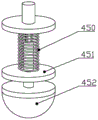
Further, as shown in fig. 18, the outer massage assembly 422 comprises an outer massage cylinder rotatably connected to the driving rod 435, the outer massage cylinder is slidably connected to a sliding plate 451, and the sliding plate 451 is connected to a side massage ball 452; the outer massage cylinder is rotatably connected with a spline, the spline is connected with a spline cylinder fixedly connected with the sliding plate 451 in a sliding mode, and the spline cylinder is sleeved with a buffer spring 450. The lateral massage ball 452 massages the waist of the patient, and the massage ball is cushioned by the cushion spring 450, thereby improving the stability of the present application.
The working process of the invention is as follows:
when the invention is used, the waist, the lumbar and the spine of the patient can be correspondingly massaged according to the condition of the patient; when the spine of the patient is massaged, the moving motor 501 acts, the moving motor 501 drives the moving cavity 502 to move upwards along the sliding rod 504 to the position, corresponding to the spine of the patient, of the middle massage structure 404 through the moving screw rod 505, and the middle massage structure 404 massages the spine and two sides of the spine of the patient; when massaging the lumbar vertebrae and the waist of the patient, the middle massage structure 404 performs stretching massage on the lumbar vertebrae and both sides of the patient, and the side massage structure 403 performs massage on the waist of the patient.
When the middle massage structure 404 is used, the driving motor 414 drives the massage screw 413 to rotate through the driving bevel gear 415 and the middle bevel gear 416, the massage screw 413 drives the vertical driving plate 407 to move up and down, and the vertical driving plate 407 drives the middle massage component 412 and the side massage structure 403 to synchronously move up and down to massage the lumbar vertebra and the waist of a patient in a reciprocating manner; meanwhile, the middle bevel gear 416 drives the reciprocating crank 410 to rotate through the driven bevel gear 417, and the reciprocating crank 410 is matched with the driving slide 418 on the driving rack 409 through the driving shaft to drive the driving rack 409 to slide along the massage cavity 402; the driving rack 409 is meshed with the driving gear 411 to drive the bidirectional crank 421 to rotate, and the bidirectional crank 421 drives the transverse sliding block 408 to slide left and right through the connecting rod 420; the horizontal sliding block 408 and the vertical driving plate 407 cooperate to drive the middle massage component 412 to move left and right while moving up and down, i.e. to continuously perform arc-shaped stretching massage from inside to outside and from outside to inside on both sides of the lumbar vertebra of the patient.
When the side massage structure 403 is in use and the middle massage structure 404 does not work, the side massage structure 403 can perform point-to-point massage on the patient; when the middle massage structure 404 works, the vertical driving board 407 drives the side massage structure 403 to move up and down to massage the patient comprehensively; when the side massage structure 403 works, the massage motor 426 acts, the massage motor 426 drives the grooved wheel 428 to rotate through the shift lever 427, the grooved wheel 428 drives the rotary gear 429 to intermittently rotate through the driving wheel 430, and the rotary gear 429 drives the rotary cavity 424 to intermittently rotate; meanwhile, when the rotary cavity 424 rotates, the planet gear 433 is driven to rotate along the sun gear 432, the planet gear 433 drives the reciprocating rack 436 to slide along the support cavity 425 in a reciprocating manner through the massage crank 434, and the reciprocating rack 436 drives the massage gear 437 to rotate; the massage gear 437 is matched with the driving rod 435 through the driving disk 438 to drive the outer massage component 422 to reciprocate along the radial direction of the rotating cavity 424; that is, while the rotating chamber 424 rotates, the outer massage component 422 reciprocates radially along the rotating chamber 424 to massage the patient; the side massage balls 452 massage the waist of the patient, and the countermeasure massage balls are cushioned by the cushion springs 450.
When the middle massage structure 404 and the side massage structures 403 are operated, the middle massage assembly 412 and the outer massage assembly 422 are operated as follows: when the middle massage component 412 moves up and down, the middle gear 441 rotates under the action of the massage rack 419; when the rotating cavity 424 rotates, the gear ring 440 drives the middle gear 441 to rotate; the middle gear 441 drives the contact rod 443 to rotate through the bevel gear set 442, the contact rod 443 drives the middle crank 445 to rotate through the pin shaft 444, when the middle crank 445 rotates to a position far away from the middle massage ball 449, the middle massage ball 449 pulls the middle crank 445 to rotate through the middle connecting rod 446 under the action of the top spring 448, and the middle massage ball 449 performs knocking massage on a patient under the action of the top spring 448.