CN113786114A - Based on intelligent healthy auxiliary robot - Google Patents
Based on intelligent healthy auxiliary robot Download PDFInfo
- Publication number
- CN113786114A CN113786114A CN202111140671.4A CN202111140671A CN113786114A CN 113786114 A CN113786114 A CN 113786114A CN 202111140671 A CN202111140671 A CN 202111140671A CN 113786114 A CN113786114 A CN 113786114A
- Authority
- CN
- China
- Prior art keywords
- fixedly connected
- bottom end
- foot bath
- water
- water inlet
- Prior art date
- Legal status (The legal status is an assumption and is not a legal conclusion. Google has not performed a legal analysis and makes no representation as to the accuracy of the status listed.)
- Pending
Links
Images




Classifications
-
- A—HUMAN NECESSITIES
- A47—FURNITURE; DOMESTIC ARTICLES OR APPLIANCES; COFFEE MILLS; SPICE MILLS; SUCTION CLEANERS IN GENERAL
- A47K—SANITARY EQUIPMENT; ACCESSORIES THEREFOR, e.g. TOILET ACCESSORIES
- A47K1/00—Wash-stands; Appurtenances therefor
- A47K1/02—Portable toilet tables; Wash cabinets or stands
-
- A—HUMAN NECESSITIES
- A47—FURNITURE; DOMESTIC ARTICLES OR APPLIANCES; COFFEE MILLS; SPICE MILLS; SUCTION CLEANERS IN GENERAL
- A47K—SANITARY EQUIPMENT; ACCESSORIES THEREFOR, e.g. TOILET ACCESSORIES
- A47K3/00—Baths; Showers; Appurtenances therefor
- A47K3/001—Accessories for baths, not provided for in other subgroups of group A47K3/00; Insertions, e.g. for babies; Tubs suspended or inserted in baths; Security or alarm devices; Protecting linings or coverings; Devices for cleaning or disinfecting baths; Bath insulation
-
- A—HUMAN NECESSITIES
- A47—FURNITURE; DOMESTIC ARTICLES OR APPLIANCES; COFFEE MILLS; SPICE MILLS; SUCTION CLEANERS IN GENERAL
- A47K—SANITARY EQUIPMENT; ACCESSORIES THEREFOR, e.g. TOILET ACCESSORIES
- A47K3/00—Baths; Showers; Appurtenances therefor
- A47K3/02—Baths
- A47K3/022—Baths specially adapted for particular use, e.g. for washing the feet, for bathing in sitting position
Landscapes
- Health & Medical Sciences (AREA)
- Public Health (AREA)
- Epidemiology (AREA)
- General Health & Medical Sciences (AREA)
- Devices For Medical Bathing And Washing (AREA)
Abstract
The invention relates to the technical field of medical assistance for major health, and discloses an intelligent health-assistance-based robot, which comprises a lifting fixing mechanism, wherein the lifting fixing mechanism comprises a first fixing cylinder, the top end of the first fixing cylinder is fixedly connected with a rotating motor, the bottom end of the rotating motor is movably connected with a rotating gear, the top end of the side surface of the rotating gear is movably connected with a rotating gear, the side surface of the rotating gear is movably engaged with a synchronous belt, and the inner side of the synchronous belt, far away from the rotating gear, is movably engaged with a transmission gear. The invention is beneficial to adjusting the height of the wash platform by arranging the rotating screw rod, the rotating gear and the moving block, the rotating screw rod is driven to rotate by the rotating gear, and the moving block can drive the wash platform to move up and down by moving up and down, so that the invention can adapt to the old with different heights, can wash the face and rinse the mouth at the upper part and can soak the feet at the lower part, and the invention can automatically move by the moving mechanism, thereby being convenient for people with inconvenient legs and feet to wash the mouth.
Description
Technical Field
The invention relates to the technical field of medical assistance for major health, in particular to an intelligent health assistance-based robot.
Background
At present, a wash basin on the market is a fixed body, people need to go to wash and rinse the face, the legs and the feet can also move, people can go to a washroom to rinse the face, the legs and the feet are not changed, people can only go to the washroom by relying on other people or reluctant rising, serious people even need the care of the people, the wash basin is a fixed body or a manual moving body, the legs and the feet can also move, but the stooping stress is difficult relatively, the people with unchanged legs and feet cannot independently complete, and the serious people even need the care of the people.
Present wash basin is fixed, footbath needs oneself to remove, the old man is alone when the family, be difficult to carry out the work of washing one's face and rinsing one's mouth, and the old man is comparatively loose and careless to the operation of electronic product, can have the condition that can't reach the operation purpose, and the old man washes one's face and rinses one's mouth, the highly fixed setting of wash platform, to the old man of different heights, be difficult to adapt to, when the old man washes one's foot or soaks one's foot, be difficult to control the temperature, because the health of old man self, it is a comparatively difficult work to empty of moisturizing or washing one's face and rinsing one's mouth back water.
Disclosure of Invention
In order to overcome the defects in the prior art, the invention provides an intelligent health-assisting robot, and the technical problems to be solved by the invention are as follows: the elderly are difficult to wash alone.
The invention provides the following technical scheme: the utility model provides a based on intelligent health auxiliary robot, includes the foot bath case, still includes:
the washing mechanism comprises: the foot bath box is arranged at the top end of the foot bath box and is fixedly connected with the foot bath box;
a water storage mechanism: the washing mechanism is arranged at the bottom end of the washing mechanism and is fixedly connected with the washing mechanism;
intelligent operating device: the water storage mechanism is arranged on the side surface of the water storage mechanism and is fixedly connected with the water storage mechanism;
and (3) a drying mechanism: the water storage mechanism is arranged on one side of the bottom end of the water storage mechanism and is fixedly connected with the water storage mechanism;
dirty water recovery mechanism: is arranged at the other side of the bottom end of the water storage mechanism and is fixedly connected with the water storage mechanism
A moving mechanism: the foot bath box is arranged at the bottom end of the foot bath box and is movably connected with the foot bath box;
the inclined structure is as follows: the foot bath box is arranged on one side of the bottom end of the foot bath box and is movably connected with the foot bath box;
raise the fixed establishment: the foot bath box is arranged on two sides of the foot bath box and is fixedly connected with the foot bath box.
In a preferred embodiment, the elevation fixing mechanism comprises a first fixed cylinder, a rotating motor is fixedly connected to the top end of the first fixed cylinder, a rotating gear is movably connected to the bottom end of the rotating motor, a rotating gear is movably connected to the top end of the side surface of the rotating gear, a synchronous belt is movably engaged with the side surface of the rotating gear, a transmission gear is movably engaged with the inner side of the synchronous belt, which is far away from the rotating gear, a transmission screw is fixedly connected to the inner side of the transmission gear, a second moving block is connected to the bottom end of the side surface of the transmission screw in a threaded manner, a second fixed sleeve is movably connected to the side surface of the second moving block in a threaded manner, a rotating screw is fixedly connected to the inner side of the rotating gear, a first moving block is connected to the bottom end of the rotating screw in a threaded manner, a first fixed cylinder is movably connected to the side surface of the first moving block, and the first moving block and the second fixed sleeve are the same in size, the rotating gear and the transmission gear are the same in size and tooth number, so that the rotating gear and the transmission gear rotate at the same speed, the rotating screw and the transmission screw rotate synchronously, and the first moving block and the second moving block move synchronously, so that the equipment is more stable when moving up and down.
In a preferred embodiment, the washing mechanism comprises a wash platform, one side of the top end of the wash platform is fixedly connected with a fixed block, the top end of the fixed block is fixedly connected with a water faucet, one side of the bottom end of the fixed block is fixedly connected with a cold water inlet pipe, the other side of the bottom end of the fixed block is fixedly connected with a hot water inlet pipe, the bottom end of the wash platform is fixedly connected with a drain pipe, one side of the bottom end of the drain pipe is fixedly connected with a connecting pipe, one side of the connecting pipe far away from the drain pipe is fixedly connected with a dirty water pipe, the cold water inlet pipe is positioned on one side of a heating plate, the hot water inlet pipe is positioned on the other side of the heating plate, the cold water inlet pipe and the hot water inlet pipe are positioned on two sides of the heating plate to conveniently extract cold water and hot water, and a platform of five to ten centimeters is reserved at the top end of the wash platform where the fixed block is positioned, can prevent some toiletries and is convenient for washing.
In a preferred embodiment, the water storage mechanism comprises a water inlet hopper, a new water inlet pipe is fixedly connected to the bottom end of the water inlet hopper, the bottom end of the fresh water inlet pipe is fixedly connected with a water inlet branch pipe, the bottom end of the water inlet branch pipe is fixedly connected with a water storage tank, the middle part of the inner side of the water storage tank is fixedly connected with a heat insulation plate, the side surface of the heat insulation plate is fixedly connected with a heating plate, the bottom end of the water storage tank is fixedly connected with a drying plate, the bottom end of the drying plate is fixedly connected with a placing plate, the diameter of the top end of the water inlet hopper is three times of that of the new water inlet pipe, a sixty-degree included angle is formed between the water inlet hopper and the horizontal direction, the inclined direction of the water inlet hopper faces back to the direction of the wash platform, the water inlet hopper is convenient for adding water, and after the water inlet hopper is inclined, water in washing can be prevented from entering the water inlet hopper, and the cleanness of water in the water storage tank is guaranteed.
In a preferred embodiment, a motor waterproof housing is fixedly connected to the top end of the first fixed cylinder, the rotating motor is located inside the motor waterproof housing, a limiting block is fixedly connected to the top end of the first fixed cylinder, a rotating cylinder is movably connected to the top end of the transmission screw rod, the top end of the rotating cylinder is fixedly connected to the top end of the second fixed sleeve, waterproof paint is brushed on the surface of the motor waterproof housing, the rotating motor is isolated from the outside through the motor waterproof housing to prevent water from entering the rotating motor and damaging equipment, and the bottom end of the limiting block is located two millimeters below the rotating gear to prevent the first moving block from contacting the rotating gear.
In a preferred embodiment, the dirty water recovery mechanism comprises a foot bath water inlet pipe, a dirty water collecting tank, a dirty water drain pipe and a drain valve, wherein a position avoiding hole is formed in the bottom end of the water storage tank, a foot bath water inlet pipe is fixedly connected in the position avoiding hole of the water storage tank, the dirty water collecting tank is fixedly connected to the bottom end of the drying plate, the foot bath water inlet pipe is located inside the dirty water collecting tank, a through hole is formed in the side surface of the dirty water collecting tank, one side of the foot bath water inlet pipe, which is far away from the drying plate, is located in the through hole of the dirty water collecting tank, the drain valve is fixedly connected to the bottom end of the side surface of the foot bath water inlet pipe, one side of the dirty water collecting tank, which is far away from the drain valve, is fixedly connected with the dirty water drain pipe, the number of the foot bath water inlet pipes is two, the two foot bath water inlet pipes are respectively located on two sides of the heat insulation plate in the water storage tank, and the foot bath water inlet pipes are located at the bottom end of the water storage tank, cold water and hot water can be applied into the foot bath box through the foot bath water inlet pipe, so that the water temperature in the foot bath box is controlled.
In a preferred embodiment, the slope structure includes spacing shell, the inside top fixedly connected with electro-magnet of spacing shell, just the top of electro-magnet and the bottom fixed connection of sufficient bath case, the inboard middle part swing joint of spacing shell has the permanent magnet, the bottom fixedly connected with buffer block of permanent magnet, the bottom of spacing shell is equipped with the spacing groove, the buffer block is located the spacing inslot of spacing shell, the bottom of spacing shell is located two millimeters below departments of buffer block bottom, the material of buffer block is the stereoplasm rubber, the side of permanent magnet is less than a millimeter with the inboard distance of electro-magnet, and the buffer block is protected by spacing shell, because its material can not produce great sound when the buffer block supports.
In a preferred embodiment, the bottom fixedly connected with connecting plate of first movable block, the bottom fixedly connected with non slipping spur of connecting plate, non slipping spur evenly distributed is in the bottom of connecting plate, the non slipping spur is equipped with the rubber material, and the distance between the non slipping spur is equipped with five millimeters to play better anti-skidding effect, prevent that the old man when using, equipment self atress and take place to slide, thereby increase the possibility that the old man fell down.
In a preferred embodiment, the bottom end of the first moving block is fixedly connected with a sucker, the diameter of the sucker is equal to the side length of the first fixed cylinder, the sucker is made of a TPE material, and the sucker is non-toxic, harmless, wear-resistant, aging-resistant, high-temperature resistant, and capable of avoiding the situation that a traditional rubber material has a peculiar smell.
The invention has the technical effects and advantages that:
1. the height of the wash platform can be adjusted conveniently by arranging the rotating screw, the rotating gear and the moving block, the rotating screw is driven to rotate by the rotating gear, so that the moving block moves downwards, and the moving block moves up and down to drive the wash platform to move up and down, so that the wash platform can adapt to the old people with different heights, and the adaptability is higher;
2. the invention realizes the integration of washing, washing and foot bathing by being provided with the washing mechanism, the foot bathing shell, the intelligent operating mechanism and the moving mechanism, can identify the sound movement of the old people for operation by being provided with the intelligent operating mechanism, can wash the face and the mouth at the upper part and can soak the feet at the lower part, and the invention can automatically move by the moving mechanism, thereby being convenient for people with inconvenient legs and feet to wash the face and the mouth;
3. the water storage tank is provided with the water storage tank, the heat insulation plate and the heating plate, so that the water temperature of the old can be adjusted conveniently, half of water in the water storage tank is automatically heated through the heating plate, and the other half of water is kept low through the heat insulation plate, so that the water temperature can be adjusted through adding cold water and hot water, and the water temperature of washing is more comfortable;
4. the invention is beneficial to discharging dirty water after washing by arranging the limiting shell, the electromagnet, the permanent magnet and the buffer block, and the buffer block is contacted with the ground by the magnetic force generated between the electromagnet and the permanent magnet, so that the integral inclined type washing machine is integrally inclined, the dirty water in the integral inclined type washing machine is convenient to drain, and the dirty water is more clean.
Drawings
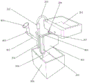
Fig. 1 is a schematic view of the overall structure of the present invention.
Fig. 2 is a schematic view of the internal structure of the present invention.
Fig. 3 is an explosion diagram of the water storage coefficient structure of the present invention.
Fig. 4 is an exploded view of the dirty water recovery mechanism of the present invention.
Fig. 5 is an exploded view of the elevated securing mechanism of the present invention.
Fig. 6 is a schematic cross-sectional view of an inclined structure according to the present invention.
Fig. 7 is a schematic structural diagram of an embodiment of the present invention.
Fig. 8 is a schematic structural diagram of a second embodiment of the present invention.
The reference signs are: 1. a foot bath box; 2. a washing mechanism; 201. a wash stand; 202. a fixed block; 203. a faucet; 204. a cold water inlet pipe; 205. a hot water inlet pipe; 206. a drain valve; 207. a sewer pipe; 208. a dirty water pipe; 209. a connecting pipe; 3. an intelligent operating mechanism; 4. a drying mechanism; 401. drying the plate; 402. placing the plate; 5. a lifting fixing mechanism; 501. a first fixed cylinder; 502. a limiting block; 503. a first moving block; 504. rotating the screw; 505. rotating the motor; 506. a waterproof housing of the motor; 507. a rotating gear; 508. a synchronous belt; 509. a transmission gear; 510. a drive screw; 511. a rotating drum; 512. a second moving block; 513. a second fixed sleeve; 514. a connecting plate; 515. anti-skid blocks; 516. a suction cup; 6. a moving mechanism; 7. a tilt structure; 701. a limiting shell; 702. an electromagnet; 703. a permanent magnet; 704. a buffer block; 8. a water storage mechanism; 801. a water inlet hopper; 802. a fresh water inlet pipe; 803. water inlet branch pipes; 804. a heat insulation plate; 805. heating plates; 806. a water storage tank; 9. a dirty water recovery mechanism; 901. a foot bath water inlet pipe; 902. a dirty water collecting tank; 903. a dirty water drain pipe; 904. and (4) draining the water valve.
Detailed Description
The technical solution of the present invention will be clearly and completely described below with reference to the accompanying drawings of the present invention, and the forms of the respective structures described in the following embodiments are merely examples, and the intelligent health assistance robot for construction sites according to the present invention is not limited to the respective structures described in the following embodiments, and all other embodiments obtained by a person having ordinary skill in the art without creative efforts belong to the scope of protection of the present invention.
The first embodiment is as follows: referring to fig. 1, the invention provides an intelligent health-assisted robot, which comprises a foot bath box 1 and further comprises:
washing mechanism 2: is arranged at the top end of the foot bath box 1 and is fixedly connected with the foot bath box 1;
a water storage mechanism 8: is arranged at the bottom end of the washing mechanism 2 and is fixedly connected with the washing mechanism 2;
intelligent operating mechanism 3: is arranged on the side surface of the water storage mechanism 8 and is fixedly connected with the water storage mechanism 8;
and a drying mechanism 4: is arranged at one side of the bottom end of the water storage mechanism 8 and is fixedly connected with the water storage mechanism 8;
dirty water recovery mechanism 9: is arranged at the other side of the bottom end of the water storage mechanism 8 and is fixedly connected with the water storage mechanism 8
The moving mechanism 6: is arranged at the bottom end of the foot bath box 1 and is movably connected with the foot bath box 1;
the inclined structure 7: is arranged at one side of the bottom end of the foot bath box 1 and is movably connected with the foot bath box 1;
the lifting fixing mechanism 5: is arranged on two sides of the foot bath box 1 and is fixedly connected with the foot bath box 1.
Referring to fig. 5, further, the elevation fixing mechanism 5 includes a first fixed cylinder 501, a rotating motor 505 is fixedly connected to a top end of the first fixed cylinder 501, a rotating gear 507 is movably connected to a bottom end of the rotating motor 505, a rotating gear 507 is movably connected to a top end of a side surface of the rotating gear 507, a synchronous belt 508 is movably engaged with a side surface of the rotating gear 507, a transmission gear 509 is movably engaged with an inner side of the synchronous belt 508 far from the rotating gear 507, a transmission screw 510 is fixedly connected to an inner portion of the transmission gear 509, a second moving block 512 is connected to a bottom end thread of a side surface of the transmission screw 510, a second fixed sleeve 513 is movably connected to a side surface of the second moving block 512, a rotating screw 504 is fixedly connected to an inner portion of the rotating gear 507, a first moving block 503 is connected to a bottom end thread of the rotating screw 504, a first fixed cylinder 501 is movably connected to a side surface of the first moving block 503, the rotating gear 507 is driven by the rotating motor 505 to rotate, therefore, the synchronous belt 508 drives the transmission gear 509 to rotate, the rotating screw 504 and the transmission screw 510 rotate to drive the first moving block 503 and the second moving block 512 to move up and down, the first moving block 503 and the second moving block 512 move up and down to enable the moving mechanism 6 to leave the ground, and at the moment, the device cannot move, so that the device is fixed at a required position.
Referring to fig. 4, further, the washing mechanism 2 includes a washing platform 201, a fixed block 202 is fixedly connected to one side of the top end of the washing platform 201, a faucet 203 is fixedly connected to the top end of the fixed block 202, a cold water inlet pipe 204 is fixedly connected to one side of the bottom end of the fixed block 202, a hot water inlet pipe 205 is fixedly connected to the other side of the bottom end of the fixed block 202, a drain pipe 207 is fixedly connected to the bottom end of the drain valve 206, a connecting pipe 209 is fixedly connected to one side of the bottom end of the drain pipe 207, a dirty water pipe 208 is fixedly connected to one side of the connecting pipe 209 away from the drain pipe 207, cold water is pumped through the cold water inlet pipe 204, hot water is pumped through the hot water inlet pipe 205, so that the temperature of water flowing out from the faucet 203 can be freely adjusted, water in the washing platform 201 can be freely discharged through the drain valve 206, and the discharged water passes through the drain pipe 207, the drain pipe 205, The connecting pipe 209 and the dirty water pipe 208 enter the dirty water collecting tank 902 to be uniformly discharged.
Referring to fig. 3 and 4, further, the water storage mechanism 8 includes a water inlet funnel 801, a new water inlet pipe 802 is fixedly connected to the bottom end of the water inlet funnel 801, a water inlet branch pipe 803 is fixedly connected to the bottom end of the new water inlet pipe 802, a water storage tank 806 is fixedly connected to the bottom end of the water inlet branch pipe 803, a heat insulation plate 804 is fixedly connected to the middle portion of the inner side of the water storage tank 806, a heating plate 805 is fixedly connected to the side surface of the heat insulation plate 804, a drying plate 401 is fixedly connected to the bottom end of the water storage tank 806, a placing plate 402 is fixedly connected to the bottom end of the drying plate 401, water can be added into the water storage tank 806 through the water inlet funnel 801, the water added into the water storage tank 806 is separated by the heat insulation plate 804, the heating plate 805 heats the water on one side, the heat insulation plate 804 prevents the water on the other side from being heated, so that cold water and hot water are simultaneously stored in the water storage tank 806, and are convenient to be used under different conditions or weathers, feet can be placed on the placing plate 402 after being soaked, drying is performed through the drying plate 401, so that the feet are prevented from falling easily when water on the feet walks.
Referring to fig. 5, further, a motor waterproof housing 506 is fixedly connected to the top end of the first fixing cylinder 501, the rotating motor 505 is located inside the motor waterproof housing 506, a limiting block 502 is fixedly connected to the top end of the first fixing cylinder 501, a rotating cylinder 511 is movably connected to the top end of the transmission screw 510, the top end of the rotating cylinder 511 is fixedly connected to the top end of the second fixing cylinder 513, the rotating gear 507 and the first moving block 503 are protected by the limiting block 502, excessive contact with the rotating gear 507 when the first moving block 503 moves upwards is prevented, damage is caused to the rotating gear 507, the rotating cylinder 511 is arranged at the top end of the transmission screw 510, the transmission screw 510 is fixed, and stability of the transmission screw 510 during rotation can be maintained.
Referring to fig. 4, further, the dirty water recycling mechanism 9 includes a foot bath water inlet pipe 901, a dirty water collecting tank 902, a dirty water drain pipe 903, and a drain valve 904, a position avoiding hole is formed at the bottom end of the water storage tank 806, the foot bath water inlet pipe 901 is fixedly connected in the position avoiding hole of the water storage tank 806, the dirty water collecting tank 902 is fixedly connected at the bottom end of the drying plate 401, the foot bath water inlet pipe 901 is located inside the dirty water collecting tank 902, a through hole is formed in the side surface of the dirty water collecting tank 902, one side of the foot bath water inlet pipe 901 away from the drying plate 401 is located in the through hole of the dirty water collecting tank 902, the drain valve 904 is fixedly connected at the bottom end of the side surface of the dirty water collecting tank 902 away from the drain valve 904, the dirty water drain pipe 903 is fixedly connected at one side of the dirty water collecting tank 902 away from the drain valve 904, cold and hot water can be applied to the foot bath tank 1 through the foot bath water inlet pipe 901, and the used water can enter the dirty water collecting tank 902 through the drain valve 904, then the sewage is discharged by a dirty water drain pipe 903, and the whole process is automatically carried out without manual operation.
Referring to fig. 6, further, the inclined structure 7 includes a limiting shell 701, the top fixedly connected with electromagnet 702 inside the limiting shell 701, and the top of electromagnet 702 and the bottom fixed connection of the lavipeditum case 1, the middle part swing joint of the inside of limiting shell 701 has a permanent magnet 703, the bottom fixedly connected with buffer block 704 of permanent magnet 703, current direction through in the electromagnet 702 changes, thereby make permanent magnet 703 drive buffer block 704 move down, buffer block 704 move down and bottom surface contact, thereby make the equipment incline, can make the cleaner entering of water in the lavipeditum case 1 at this moment dirty water collecting box 902 in, and accelerate the speed that the water in the dirty water collecting box 902 flows out from dirty water drain pipe 903.
The working principle of the first embodiment of the invention is as follows: s1, firstly, collecting water in a water storage tank 806 through a water inlet hopper 801, working through a heating plate 805, heating the water on one side, when washing, enabling the hot water and the cold water to flow out through a cold water inlet pipe 204 and a hot water inlet pipe 205 respectively, enabling the hot water and the cold water to enter a faucet 203 for mixing, ensuring that the water temperature is comfortable when washing, after washing, opening a water outlet valve 206, and enabling dirty water to enter a dirty water collecting tank 902 through a sewer pipe 207, a connecting pipe 209 and a dirty water pipe 208 for collection;
s2, cold water and hot water in the water storage tank 806 enter the foot bath box 1 through the foot bath water inlet pipe 901, when feet are soaked, the water temperature can be controlled through the intelligent operating mechanism 3, the display screen on the intelligent operating mechanism 3 can perform video communication with relatives at the moment, and after the feet are soaked, the feet are placed on the placing plate 402 and dried through the drying plate 401;
s3, when dirty water is discharged, the electromagnet 702 is started, the electromagnet 702 drives the permanent magnet 703 to move downwards, so that the buffer block 704 moves downwards, the buffer block 704 supports the equipment, the equipment is kept inclined, dirty water in the dirty water collecting box 902 flows out through the dirty water drain pipe 903, dirty water in the foot bath box 1 enters the dirty water collecting box 902 through the drain valve 904 and is discharged through the dirty water collecting box 902;
s4, when the height of the wash mouth is adjusted, the rotating motor 505 is started to drive the rotating screw 504 to rotate, the rotating screw 504 rotates to drive the synchronous belt 508 to rotate through the rotating gear 507, so that the synchronous belt 508 drives the transmission gear 509 to rotate, the transmission gear 509 rotates to drive the second moving block 512 to move up and down, the rotating screw 504 rotates to drive the first moving block 503 to move up and down, and the first moving block 503 and the second moving block 512 adjust the overall height of the wash mouth mechanism 2, so that the wash mouth mechanism 2 can adapt to different users.
Example two:
referring to fig. 7, further, the bottom end fixedly connected with connecting plate 514 of first movable block 503, the bottom end fixedly connected with non-slipping spur 515 of connecting plate 514, non-slipping spur 515 evenly distributed is in the bottom of connecting plate 514, through being equipped with a plurality of non-slipping spurs 515, thereby when making the equipment atress, non-slipping spur 515 extrudes each other, thereby offset the power that receives, makes equipment be difficult for removing, consequently stability and security when improving the use, embodiment two lies in with embodiment one's difference: the connecting plate 514 and the anti-slip block 515 are additionally arranged at the bottom end of the first moving block 503, the anti-slip block 515 increases an anti-slip effect, and the situation that the first moving block 503 supports the ground when the ground is slippery can be prevented, so that the situation of slippage is generated.
Example three:
referring to fig. 8, further, a suction cup 516 is fixedly connected to the bottom end of the first moving block 503, the diameter of the suction cup 516 is equal to the side length of the first fixing cylinder 501, and the suction cup 516 can automatically suck the device together with the ground after moving downwards, so that the device is fixed by a fixing column, and when the device cannot be used on the ground fixed by air pressure, the suction cup 516 can contact with the ground to increase friction, so that the device is safer when in use, and the difference between the third embodiment and the first embodiment is that: in the third embodiment, the suction cup 516 is additionally arranged at the bottom end of the first moving block 503, so that the first moving block 503 cannot move due to stress when supporting the device, and the old can be prevented from falling down due to the device when using the old, and the old is safer to use.
The points to be finally explained are: first, in the description of the present application, it should be noted that, unless otherwise specified and limited, the terms "mounted," "connected," and "connected" should be understood broadly, and may be a mechanical connection or an electrical connection, or a communication between two elements, and may be a direct connection, and "upper," "lower," "left," and "right" are only used to indicate a relative positional relationship, and when the absolute position of the object to be described is changed, the relative positional relationship may be changed;
secondly, the method comprises the following steps: in the drawings of the disclosed embodiments of the invention, only the structures related to the disclosed embodiments are referred to, other structures can refer to common designs, and the same embodiment and different embodiments of the invention can be combined with each other without conflict;
and finally: the above description is only for the purpose of illustrating the preferred embodiments of the present invention and is not to be construed as limiting the invention, and any modifications, equivalents, improvements and the like that are within the spirit and principle of the present invention are intended to be included in the scope of the present invention.
Claims (9)
1. The utility model provides a based on intelligent healthy supplementary robot, includes foot bath (1), its characterized in that still includes:
washing mechanism (2): the foot bath box is arranged at the top end of the foot bath box (1) and is fixedly connected with the foot bath box (1);
water storage mechanism (8): the washing machine is arranged at the bottom end of the washing mechanism (2) and is fixedly connected with the washing mechanism (2);
intelligent operating mechanism (3): the water storage mechanism is arranged on the side surface of the water storage mechanism (8) and is fixedly connected with the water storage mechanism (8);
drying mechanism (4): the water storage mechanism is arranged on one side of the bottom end of the water storage mechanism (8) and is fixedly connected with the water storage mechanism (8);
dirty water recovery mechanism (9): is arranged at the other side of the bottom end of the water storage mechanism (8) and is fixedly connected with the water storage mechanism (8)
Moving mechanism (6): the foot bath box is arranged at the bottom end of the foot bath box (1) and is movably connected with the foot bath box (1);
inclined structure (7): the foot bath box is arranged on one side of the bottom end of the foot bath box (1) and is movably connected with the foot bath box (1);
elevation fixing mechanism (5): are arranged on two sides of the foot bath box (1) and are fixedly connected with the foot bath box (1).
2. The intelligent health-assistance-based robot according to claim 1, wherein: the lifting fixing mechanism (5) comprises a first fixing barrel (501), a rotating motor (505) is fixedly connected to the top end of the first fixing barrel (501), a rotating gear (507) is movably connected to the bottom end of the rotating motor (505), a rotating gear (507) is movably connected to the top end of the side face of the rotating gear (507), a synchronous belt (508) is movably meshed to the side face of the rotating gear (507), a transmission gear (509) is movably meshed to the inner side, far away from the rotating gear (507), of the synchronous belt (508), a transmission screw (510) is fixedly connected to the inner portion of the transmission gear (509), a second moving block (512) is connected to the bottom end of the side face of the transmission screw (510) in a threaded mode, a second fixing sleeve (513) is movably connected to the side face of the second moving block (512), and a rotating screw (504) is fixedly connected to the inner portion of the rotating gear (507), the bottom end of the rotating screw rod (504) is in threaded connection with a first moving block (503), and the side surface of the first moving block (503) is movably connected with a first fixed cylinder (501).
3. The intelligent health-assistance-based robot according to claim 1, wherein: the washing mechanism (2) comprises a washing table (201), one side of the top end of the washing table (201) is fixedly connected with a fixing block (202), the top end of the fixing block (202) is fixedly connected with a faucet (203), one side of the bottom end of the fixing block (202) is fixedly connected with a cold water inlet pipe (204), the other side of the bottom end of the fixing block (202) is fixedly connected with a hot water inlet pipe (205), the bottom end of the washing table (201) is fixedly connected with a drain valve (206), the bottom end of the drain valve (206) is fixedly connected with a drain pipe (207), one side of the bottom end of the drain pipe (207) is fixedly connected with a connecting pipe (209), and one side of the connecting pipe (209) away from the drain pipe (207) is fixedly connected with a dirty water pipe (208).
4. The intelligent health-assistance-based robot according to claim 1, wherein: the water storage mechanism (8) comprises a water inlet hopper (801), a bottom fixedly connected with new water inlet pipe (802) of the water inlet hopper (801), a bottom fixedly connected with water inlet branch pipe (803) of the new water inlet pipe (802), a bottom fixedly connected with water storage tank (806) of the water inlet branch pipe (803), a middle fixedly connected with heat insulation plate (804) on the inner side of the water storage tank (806), a side fixedly connected with heating plate (805) of the heat insulation plate (804), a bottom fixedly connected with drying plate (401) of the water storage tank (806), and a bottom fixedly connected with placing plate (402) of the drying plate (401).
5. The intelligent health-assistance-based robot according to claim 2, wherein: the top fixedly connected with motor waterproof case (506) of first fixed cylinder (501), it is located the inside of motor waterproof case (506) to rotate motor (505), the inside top fixedly connected with stopper (502) of first fixed cylinder (501), the top swing joint of drive screw (510) has rotary drum (511), the top of rotary drum (511) and the inside top fixed connection of second fixed sleeve (513).
6. The intelligent health-assisting robot based on any one of claims 1 to 4, wherein: the dirty water recovery mechanism (9) comprises a foot bath water inlet pipe (901), a dirty water collecting box (902), a dirty water drain pipe (903) and a drain valve (904), a position avoiding hole is arranged at the bottom end of the water storage tank (806), a foot bath water inlet pipe (901) is fixedly connected in the position avoiding hole of the water storage tank (806), the bottom end of the drying plate (401) is fixedly connected with a dirty water collecting box (902), the foot bath water inlet pipe (901) is positioned inside the dirty water collecting box (902), a through hole is formed in the side surface of the dirty water collecting box (902), one side of the foot bath water inlet pipe (901) far away from the drying plate (401) is positioned in the through hole of the dirty water collecting box (902), the bottom end of the side surface of the dirty water collecting box (902) where the foot bath water inlet pipe (901) is positioned is fixedly connected with a drain valve (904), and a dirty water drain pipe (903) is fixedly connected to one side of the dirty water collecting box (902) far away from the drain valve (904).
7. The intelligent health-assistance-based robot according to claim 1, wherein: the inclined structure (7) comprises a limiting shell (701), an electromagnet (702) is fixedly connected to the top end inside the limiting shell (701), the top end of the electromagnet (702) is fixedly connected with the bottom end of the foot bath box (1), a permanent magnet (703) is movably connected to the middle of the inner side of the limiting shell (701), and a buffer block (704) is fixedly connected to the bottom end of the permanent magnet (703).
8. The intelligent health-assistance-based robot according to claim 2, wherein: the bottom end of the first moving block (503) is fixedly connected with a connecting plate (514), the bottom end of the connecting plate (514) is fixedly connected with anti-skidding blocks (515), and the anti-skidding blocks (515) are uniformly distributed at the bottom end of the connecting plate (514).
9. The intelligent health-assistance-based robot according to claim 2, wherein: the bottom end of the first moving block (503) is fixedly connected with a sucker (516), and the diameter of the sucker (516) is equal to the side length of the first fixed cylinder (501).
Priority Applications (1)
| Application Number | Priority Date | Filing Date | Title |
|---|---|---|---|
| CN202111140671.4A CN113786114A (en) | 2021-09-28 | 2021-09-28 | Based on intelligent healthy auxiliary robot |
Applications Claiming Priority (1)
| Application Number | Priority Date | Filing Date | Title |
|---|---|---|---|
| CN202111140671.4A CN113786114A (en) | 2021-09-28 | 2021-09-28 | Based on intelligent healthy auxiliary robot |
Publications (1)
| Publication Number | Publication Date |
|---|---|
| CN113786114A true CN113786114A (en) | 2021-12-14 |
Family
ID=79184670
Family Applications (1)
| Application Number | Title | Priority Date | Filing Date |
|---|---|---|---|
| CN202111140671.4A Pending CN113786114A (en) | 2021-09-28 | 2021-09-28 | Based on intelligent healthy auxiliary robot |
Country Status (1)
| Country | Link |
|---|---|
| CN (1) | CN113786114A (en) |
Cited By (1)
| Publication number | Priority date | Publication date | Assignee | Title |
|---|---|---|---|---|
| CN116619410A (en) * | 2023-05-31 | 2023-08-22 | 清远市伽蓝洁具有限公司 | washbasin cleaning robot |
Citations (10)
| Publication number | Priority date | Publication date | Assignee | Title |
|---|---|---|---|---|
| CN103195144A (en) * | 2013-03-26 | 2013-07-10 | 吴良峰 | Foot bath device |
| CN104032543A (en) * | 2013-11-30 | 2014-09-10 | 西安三威安防科技有限公司 | Lifting device for washing machines |
| CN204698411U (en) * | 2015-06-24 | 2015-10-14 | 浙江树人建设有限公司 | Be convenient to the Wash Units of movement |
| CN105650862A (en) * | 2016-03-17 | 2016-06-08 | 孙新建 | Self-cleaning type variable volume water heater |
| CN106955046A (en) * | 2017-04-10 | 2017-07-18 | 浙江工贸职业技术学院 | A kind of Pediluvium apparatus with drying function |
| CN210541212U (en) * | 2019-05-24 | 2020-05-19 | 深圳市全品医疗科技有限公司 | Inflatable bathtub |
| CN210673161U (en) * | 2019-08-13 | 2020-06-05 | 郑州儿童医院 | A belt cleaning device for paediatrics nursing |
| CN111603339A (en) * | 2020-06-04 | 2020-09-01 | 南通大学 | A multifunctional washing car for preventing cross infection of ICU patients |
| CN213233657U (en) * | 2020-05-29 | 2021-05-18 | 王炳尧 | Vertical and horizontal removal wash platform |
| CN213787064U (en) * | 2020-11-11 | 2021-07-27 | 帝欧家居股份有限公司 | A smart washstand based on smart home |
-
2021
- 2021-09-28 CN CN202111140671.4A patent/CN113786114A/en active Pending
Patent Citations (10)
| Publication number | Priority date | Publication date | Assignee | Title |
|---|---|---|---|---|
| CN103195144A (en) * | 2013-03-26 | 2013-07-10 | 吴良峰 | Foot bath device |
| CN104032543A (en) * | 2013-11-30 | 2014-09-10 | 西安三威安防科技有限公司 | Lifting device for washing machines |
| CN204698411U (en) * | 2015-06-24 | 2015-10-14 | 浙江树人建设有限公司 | Be convenient to the Wash Units of movement |
| CN105650862A (en) * | 2016-03-17 | 2016-06-08 | 孙新建 | Self-cleaning type variable volume water heater |
| CN106955046A (en) * | 2017-04-10 | 2017-07-18 | 浙江工贸职业技术学院 | A kind of Pediluvium apparatus with drying function |
| CN210541212U (en) * | 2019-05-24 | 2020-05-19 | 深圳市全品医疗科技有限公司 | Inflatable bathtub |
| CN210673161U (en) * | 2019-08-13 | 2020-06-05 | 郑州儿童医院 | A belt cleaning device for paediatrics nursing |
| CN213233657U (en) * | 2020-05-29 | 2021-05-18 | 王炳尧 | Vertical and horizontal removal wash platform |
| CN111603339A (en) * | 2020-06-04 | 2020-09-01 | 南通大学 | A multifunctional washing car for preventing cross infection of ICU patients |
| CN213787064U (en) * | 2020-11-11 | 2021-07-27 | 帝欧家居股份有限公司 | A smart washstand based on smart home |
Cited By (1)
| Publication number | Priority date | Publication date | Assignee | Title |
|---|---|---|---|---|
| CN116619410A (en) * | 2023-05-31 | 2023-08-22 | 清远市伽蓝洁具有限公司 | washbasin cleaning robot |
Similar Documents
| Publication | Publication Date | Title |
|---|---|---|
| CN107374525A (en) | Wall cleaning equipment between a kind of bathing | |
| CN205007181U (en) | Patient's device of bathing | |
| CN101684668B (en) | Water-saving splashproof woman washing integrating pedestal pan | |
| CN201046086Y (en) | Shower apparatus for scrubbing and washing | |
| CN204207643U (en) | A bath tub capable of lifting a baby out of the water | |
| CN108625442A (en) | It is a kind of can the high Wash Units of adjust automatically | |
| CN105725898B (en) | Reciprocating automatic scrubbing and washing machine | |
| CN205650513U (en) | Quick belt cleaning device of obstetrical department's apparatus | |
| CN108634855B (en) | Toilet assisting system and method for trunk muscle injury | |
| CN110772146A (en) | Multifunctional household bathing robot device | |
| CN101385631B (en) | Sole cleaner | |
| CN213233657U (en) | Vertical and horizontal removal wash platform | |
| CN105595884A (en) | Shower with scrub-washing function | |
| CN211461170U (en) | Patient rehabilitation nursing is with multi-functional medicine fumigation and washing device | |
| CN216934246U (en) | Cleaning device for anorectal patient | |
| CN202236057U (en) | Auxiliary device for bathing | |
| CN202477611U (en) | Plane mop washing machine | |
| CN205585924U (en) | Novel immediately, put formula bathtub | |
| CN207332368U (en) | A kind of multifunctional bath room | |
| CN201911987U (en) | Footbath scouring device | |
| CN216840840U (en) | Antibacterial and anti-skid integral bathroom | |
| CN2153317Y (en) | automatic washing machine | |
| CN206581356U (en) | Closestool bathroom combination sideboard | |
| CN215993751U (en) | Double-layer washstand basin | |
| CN205697492U (en) | Reciprocating automatic scrub machine |
Legal Events
| Date | Code | Title | Description |
|---|---|---|---|
| PB01 | Publication | ||
| PB01 | Publication | ||
| SE01 | Entry into force of request for substantive examination | ||
| SE01 | Entry into force of request for substantive examination | ||
| RJ01 | Rejection of invention patent application after publication |
Application publication date: 20211214 |
|
| RJ01 | Rejection of invention patent application after publication |