CN113753709A - Traction drive passenger elevator with power failure protection function - Google Patents
Traction drive passenger elevator with power failure protection function Download PDFInfo
- Publication number
- CN113753709A CN113753709A CN202111317307.0A CN202111317307A CN113753709A CN 113753709 A CN113753709 A CN 113753709A CN 202111317307 A CN202111317307 A CN 202111317307A CN 113753709 A CN113753709 A CN 113753709A
- Authority
- CN
- China
- Prior art keywords
- elevator
- traction
- fixedly arranged
- cavity
- sliding
- Prior art date
- Legal status (The legal status is an assumption and is not a legal conclusion. Google has not performed a legal analysis and makes no representation as to the accuracy of the status listed.)
- Granted
Links
Images


Classifications
-
- B—PERFORMING OPERATIONS; TRANSPORTING
- B66—HOISTING; LIFTING; HAULING
- B66B—ELEVATORS; ESCALATORS OR MOVING WALKWAYS
- B66B5/00—Applications of checking, fault-correcting, or safety devices in elevators
- B66B5/02—Applications of checking, fault-correcting, or safety devices in elevators responsive to abnormal operating conditions
- B66B5/16—Braking or catch devices operating between cars, cages, or skips and fixed guide elements or surfaces in hoistway or well
-
- B—PERFORMING OPERATIONS; TRANSPORTING
- B66—HOISTING; LIFTING; HAULING
- B66B—ELEVATORS; ESCALATORS OR MOVING WALKWAYS
- B66B5/00—Applications of checking, fault-correcting, or safety devices in elevators
- B66B5/02—Applications of checking, fault-correcting, or safety devices in elevators responsive to abnormal operating conditions
- B66B5/04—Applications of checking, fault-correcting, or safety devices in elevators responsive to abnormal operating conditions for detecting excessive speed
- B66B5/06—Applications of checking, fault-correcting, or safety devices in elevators responsive to abnormal operating conditions for detecting excessive speed electrical
-
- B—PERFORMING OPERATIONS; TRANSPORTING
- B66—HOISTING; LIFTING; HAULING
- B66B—ELEVATORS; ESCALATORS OR MOVING WALKWAYS
- B66B5/00—Applications of checking, fault-correcting, or safety devices in elevators
- B66B5/28—Buffer-stops for cars, cages, or skips
- B66B5/284—Buffer-stops for cars, cages, or skips mounted on cars or counterweights
Abstract
The invention discloses a traction drive passenger elevator with a power failure protection function, which comprises an elevator box, wherein an elevator cavity is formed in the elevator box, an elevator is arranged in the elevator cavity in a sliding manner, a top plate is fixedly arranged on the upper side of the elevator, a traction machine is fixedly arranged on the top surface of the top plate, a traction cavity is formed in the front side surface of the traction machine, a main shaft is rotatably arranged on the rear wall of the traction cavity, a traction wheel is fixedly arranged on the periphery of the main shaft, a traction rope is fixedly arranged on the top surface of the elevator, a supporting plate is fixedly arranged on the rear wall of the elevator cavity, a positioner is fixedly arranged on the left side surface of the supporting plate, two bilaterally symmetrical brake curved rods are rotatably arranged in the traction cavity, a first clamping block is fixedly arranged on the top surface of the elevator, a fixed plate is fixedly arranged on the rear wall of the elevator cavity, and a second clamping block is slidably arranged on the top surface of the elevator, thereby avoiding the elevator to continue to fall and ensuring that the passengers leave the elevator safely.
Description
Technical Field
The invention relates to the technical field of elevator power failure protection, in particular to a traction drive passenger elevator with a power failure protection function.
Background
The elevator is necessary transportation equipment of a high-rise building, when power failure occurs, the elevator cannot run, if braking measures are not taken in time, the elevator can have the risk of falling, the life safety of passengers in the elevator cannot be guaranteed, and when a traction machine fails, the elevator can slide in an overspeed manner, so that the passengers in the elevator are injured or even die;
and when the elevator is fixed at higher position, if evacuate the passenger in the elevator, can make the elevator produce the vibration certainly to lead to the risk that the elevator secondary falls, the elevator is falling down and is hitting the bottom or when shifting up and hitting the top simultaneously, can produce great vibration, leads to passenger's body to feel uncomfortable or be injured.
Disclosure of Invention
The invention aims to provide a traction drive passenger elevator with a power failure protection function, which is used for overcoming the defects in the prior art.
The invention relates to a traction drive passenger elevator with a power failure protection function, which comprises an elevator cage, an elevator cavity is arranged in the elevator cage, an elevator is arranged in the elevator cavity in a sliding manner, a top plate is fixedly arranged on the upper side of the elevator, a traction machine is fixedly arranged on the top surface of the top plate, a traction cavity is arranged on the front side surface of the traction machine, a main shaft is rotatably arranged on the rear wall of the traction cavity, a traction sheave is fixedly arranged on the periphery of the main shaft, a traction rope is fixedly arranged on the top surface of the elevator, the traction rope is used for dragging the elevator, the traction rope is wound on the periphery of the traction sheave, a smooth cavity is arranged on the bottom surface of the top plate, an auxiliary shaft is rotatably arranged on the rear wall of the smooth cavity, a pulley is fixedly arranged on the periphery of the auxiliary shaft, the traction rope can slide on the periphery of the pulley, a traction block is arranged in the elevator cavity in a sliding mode, and the top surface of the traction block is fixed with the traction rope;
a supporting plate is fixedly arranged on the rear wall of the elevator cavity, a positioner is fixedly arranged on the left side surface of the supporting plate and used for detecting the position of the elevator, a sliding cavity is formed in the front side surface of the supporting plate, a sliding plate extending forwards is arranged in the sliding cavity in a sliding mode, a rotating shaft is rotatably arranged in the front side surface of the sliding plate, a supporting rod is fixedly arranged on the periphery of the rotating shaft, and the supporting rod is used for supporting the elevator;
two bilaterally symmetrical brake curved rods are rotatably arranged in the traction cavity, the two spring blocks can stop the traction sheave from rotating, a hinge block is fixedly arranged on the bottom wall of the traction cavity and is hinged with the bottom ends of the two braking curved rods, a first clamping block is fixedly arranged on the top surface of the elevator, a fixing plate is fixedly arranged on the rear wall of the elevator cavity, the left side surface of the fixed plate is abutted against the right side surface of the first clamping block, a second clamping block is arranged on the top surface of the elevator in a sliding manner, the fixed plate is positioned between the first clamping block and the second clamping block, a threaded rod is rotatably arranged on the right side surface of the first clamping block and penetrates through the second clamping block, and the peripheral surface of the threaded rod is in threaded connection with the second clamping block, and the elevator can be prevented from falling down through the first clamping block and the threaded rod.
Preferably, two damping boxes which are symmetrical left and right are fixedly arranged on the top surface of the elevator, first damping plates are arranged in the two damping boxes in a sliding manner, first springs are fixedly arranged on the top surfaces of the two first damping plates, the top ends of the two first springs are fixed with the bottom surface of the elevator, the top plate is fixed with the inner wall of the elevator cavity, a shock absorption rod is arranged on the top plate in a sliding mode and penetrates through the top plate, a second damping plate is fixedly arranged at the bottom end of the damping rod, a second spring is fixedly arranged on the top surface of the second damping plate, the top end of the second spring is fixed with the bottom surface of the top plate, the first spring and the second spring can play a role in damping and buffering the elevator, fixed blocks are fixedly arranged on the bottom surfaces of the two first damping plates, and the two fixed blocks penetrate through the bottom surfaces of the damping boxes on the same side with the fixed blocks respectively.
Preferably, two cam cavities which are bilaterally symmetrical are formed in the inner wall of the traction cavity, cam shafts are rotatably arranged on the rear walls of the two cam cavities, cams are fixedly arranged on the peripheries of the two cam shafts, the peripheral surfaces of the two cams are respectively abutted against the peripheral surfaces of the brake curved bars on the same side, the two brake curved bars can mutually approach and rotate through the cams on the same side, spring blocks are fixedly arranged at the top ends of the two brake curved bars, a third spring is fixedly arranged between the two spring blocks, the surfaces, close to each other, of the two spring blocks are connected through the third spring, cam motors are fixedly arranged in the rear walls of the two cam cavities, the two cam motors are respectively in power connection with the cam shafts on the same side, a first power supply is fixedly arranged on the left side surface of the traction machine and used for supplying power to the two cam motors, thereby ensuring that the cam motor can still operate when power is cut off.
Preferably, a sliding shaft extending backwards is rotatably arranged on the sliding plate, a sliding gear is fixedly arranged on the periphery of the sliding shaft and is meshed with the left wall of the sliding cavity, the sliding plate can slide up and down through the sliding gear, a sliding motor is fixedly arranged in the sliding plate and is in power connection with the sliding shaft, a rotating motor is fixedly arranged in the front side face of the sliding plate and is in power connection with the rotating shaft, a second power supply is fixedly arranged on the front side face of the sliding plate and is used for supplying power to the rotating motor and the sliding motor, and therefore the rotating motor and the sliding motor can still run when power is cut off.
Preferably, a screw motor is fixedly arranged in the first clamping block, the screw motor is in power connection with the threaded rod, the second clamping block can slide leftwards through the threaded rod, so that the first clamping block and the threaded rod can clamp the column and the fixing plate, the elevator can be fixed, a velocimeter is fixedly arranged on the top surface of the first clamping block, the velocimeter is used for measuring the moving speed of the elevator, and the velocimeter can transmit a speed signal to the screw motor to enable the screw motor to be started.
Preferably, the positioner can transmit position information to the sliding motor, so that the sliding motor is started, the sliding gear can rotate, a traction motor is fixedly arranged in the rear wall of the traction cavity, the traction motor is in power connection with the spindle, a limiting cavity is formed in the rear wall of the elevator cavity, and the rear side surface of the traction block is inserted into the limiting cavity, so that the traction block is prevented from swinging in the elevator cavity.
The invention has the beneficial effects that: the traction drive passenger elevator with the power failure protection function can perform emergency braking on the elevator when power fails so as to prevent the elevator from falling, is provided with the velometer and the clamping device, can fix the elevator on the fixing plate so as to prevent the elevator from sliding in an overspeed manner, is provided with the positioner and the safety support device so as to rapidly position and support the elevator so as to prevent the elevator from continuously falling, and can ensure that passengers safely leave the elevator.
Drawings
Fig. 1 is an external view of a traction drive passenger elevator with power failure protection function according to the present invention;
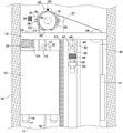
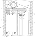
fig. 2 is a schematic cross-sectional view of a traction drive passenger elevator with power failure protection of the present invention;
fig. 3 is an enlarged schematic view of the traction machine of fig. 2 according to the present invention;
FIG. 4 is a schematic right view of the slide plate of FIG. 2 in accordance with the present invention;
fig. 5 is an enlarged partial schematic view of the invention at a in fig. 2.
In the figure:
10. an elevator cage; 11. an elevator chamber; 12. a top plate; 13. an elevator; 14. a damper box; 15. a first spring; 16. a first damper plate; 17. a fixed block; 18. a fixing plate; 19. a first clamping block; 20. a threaded rod; 21. a second clamping block; 22. a hoisting rope; 23. a second spring; 24. a second damper plate; 25. a shock-absorbing lever; 26. a first power supply; 27. a traction machine; 28. a cam cavity; 29. a traction cavity; 30. a main shaft; 31. a brake crank; 32. a hinged block; 33. a third spring; 34. a camshaft; 35. a cam; 36. a spring block; 37. a smooth cavity; 38. a counter shaft; 39. a pulley; 40. a confinement chamber; 41. a dragging block; 42. a support plate; 43. a positioner; 44. a sliding cavity; 45. a sliding plate; 46. a sliding shaft; 47. a sliding gear; 48. a second power supply; 49. a rotating shaft; 50. a support bar; 51. a traction sheave; 52. a velocimeter.
Detailed Description
The technical solutions in the embodiments of the present invention will be clearly and completely described below with reference to the drawings in the embodiments of the present invention, and it is obvious that the described embodiments are only a part of the embodiments of the present invention, and not all of the embodiments. All other embodiments, which can be derived by a person skilled in the art from the embodiments given herein without making any creative effort, shall fall within the protection scope of the present invention.
Referring to fig. 1 to 5, a traction-driven passenger elevator with a power failure protection function according to an embodiment of the present invention includes an elevator cage 10, an elevator cavity 11 is formed in the elevator cage 10, an elevator 13 is slidably disposed in the elevator cavity 11, a top plate 12 is fixedly disposed on an upper side of the elevator 13, a traction machine 27 is fixedly disposed on a top surface of the top plate 12, a traction cavity 29 is formed on a front side surface of the traction machine 27, a main shaft 30 is rotatably disposed on a rear wall of the traction cavity 29, a traction sheave 51 is fixedly disposed on an outer periphery of the main shaft 30, a traction rope 22 is fixedly disposed on a top surface of the elevator 13, the traction rope 22 is used for traction of the elevator 13, the traction rope 22 is wound on an outer periphery of the traction sheave 51, a smooth cavity 37 is formed on a bottom surface of the top plate 12, a counter shaft 38 is rotatably disposed on a rear wall of the smooth cavity 37, a pulley 39 is fixedly disposed on an outer periphery of the counter shaft 38, the hoisting rope 22 can slide on the periphery of the pulley 39, a hoisting block 41 is arranged in the elevator cavity 11 in a sliding mode, and the top surface of the hoisting block 41 is fixed with the hoisting rope 22;
a supporting plate 42 is fixedly arranged on the rear wall of the elevator cavity 11, a positioner 43 is fixedly arranged on the left side surface of the supporting plate 42, the positioner 43 is used for detecting the position of the elevator 13, a sliding cavity 44 is arranged on the front side surface of the supporting plate 42, a sliding plate 45 extending forwards is slidably arranged in the sliding cavity 44, a rotating shaft 49 is rotatably arranged on the front side surface of the sliding plate 45, a supporting rod 50 is fixedly arranged on the periphery of the rotating shaft 49, and the supporting rod 50 is used for supporting the elevator 13;
two bilaterally symmetrical brake curved rods 31 are rotatably arranged in the traction chamber 29, two spring blocks 36 can stop the traction sheave 51 from rotating, a hinging block 32 is fixedly arranged on the bottom wall of the traction cavity 29, the hinging block 32 is hinged with the bottom ends of the two braking curved rods 31, a first clamping block 19 is fixedly arranged on the top surface of the elevator 13, a fixing plate 18 is fixedly arranged on the rear wall of the elevator cavity 11, the left side surface of the fixing plate 18 is abutted against the right side surface of the first clamping block 19, the top surface of the elevator 13 is provided with a second clamping block 21 in a sliding way, the fixing plate 18 is located between the first clamping block 19 and the second clamping block 21, a threaded rod 20 is rotatably arranged on the right side surface of the first clamping block 19, the threaded rod 20 penetrates through the second clamping block 21, the peripheral surface of the threaded rod 20 is in threaded connection with the second clamping block 21, the elevator 13 can be prevented from falling by the first clamp block 19 and the threaded rod 20.
Beneficially, two damping boxes 14 which are symmetrical left and right are fixedly arranged on the top surface of the elevator 13, first damping plates 16 are slidably arranged in the two damping boxes 14, first springs 15 are fixedly arranged on the top surfaces of the two first damping plates 16, the top ends of the two first springs 15 are fixedly arranged on the bottom surface of the elevator 13, the top plate 12 is fixedly arranged on the inner wall of the elevator cavity 11, damping rods 25 are slidably arranged on the top plate 12, the damping rods 25 penetrate through the top plate 12, second damping plates 24 are fixedly arranged on the bottom ends of the damping rods 25, second springs 23 are fixedly arranged on the top surfaces of the second damping plates 24, the top ends of the second springs 23 are fixedly arranged on the bottom surface of the top plate 12, the first springs 15 and the second springs 23 can play a role in damping and buffering the elevator 13, fixed blocks 17 are fixedly arranged on the bottom surfaces of the two first damping plates 16, the two fixing blocks 17 penetrate through the bottom surfaces of the damping boxes 14 on the same side, when the two fixing blocks 17 abut against the bottom surfaces, if the elevator 13 continuously falls down, the two damping boxes 14 continuously fall down, the two first springs 15 are extruded and deformed, and when the top surface of the elevator 13 abuts against the second damping plate 24, if the elevator 13 continuously slides upwards, the second damping plate 24 can be pushed to continuously slide upwards, and the second springs 23 are extruded and deformed.
Beneficially, two cam cavities 28 which are bilaterally symmetrical are formed in the inner wall of the traction cavity 29, cam shafts 34 are rotatably arranged on the rear walls of the two cam cavities 28, cams 35 are fixedly arranged on the peripheries of the two cam shafts 34, the outer peripheries of the two cams 35 are respectively abutted to the outer peripheries of the brake curved levers 31 on the same side, the two brake curved levers 31 can mutually approach and rotate through the cams 35 on the same side, spring blocks 36 are fixedly arranged at the top ends of the two brake curved levers 31, a third spring 33 is fixedly arranged between the two spring blocks 36, the surfaces, which approach to each other, of the two spring blocks 36 are connected through the third spring 33, cam motors are fixedly arranged in the rear walls of the two cam cavities 28, the two cam motors are respectively in power connection with the cam shafts 34 on the same side, and a first power supply 26 is fixedly arranged on the left side surface of the traction machine 27, the first power source 26 is used to supply power to the two cam motors, so as to ensure that the cam motors can still operate when power is cut off, and the cam motors are turned on to rotate the cam shafts 34.
Advantageously, a sliding shaft 46 extending backwards is rotatably arranged on the sliding plate 45, a sliding gear 47 is fixedly arranged on the outer periphery of the sliding shaft 46, the sliding gear 47 is engaged with the left wall of the sliding cavity 44, the sliding plate 45 can slide up and down through the sliding gear 47, a sliding motor is fixedly arranged in the sliding plate 45, the sliding motor is in power connection with the sliding shaft 46, a rotating motor is fixedly arranged in the front side surface of the sliding plate 45, the rotating motor is in power connection with the rotating shaft 49, a second power source 48 is fixedly arranged on the front side surface of the sliding plate 45, the second power source 48 is used for supplying power to the rotating motor and the sliding motor, so that the rotating motor and the sliding motor can still operate when power is cut off, the sliding motor is turned on, the sliding shaft 46 is rotated, and the rotating motor is turned on, the rotating shaft 49 is rotated.
Advantageously, a screw motor is fixedly arranged in the first clamping block 19, the screw motor is in power connection with the threaded rod 20, the second clamping block 21 can be slid leftwards through the threaded rod 20, so that the first clamping block 19 and the threaded rod 20 can clamp the column fixing plate 18, so that the elevator 13 can be fixed, a tachometer 52 is fixedly arranged on the top surface of the first clamping block 19, the tachometer 52 is used for measuring the moving speed of the elevator 13, and the tachometer 52 can transmit a speed signal to the screw motor, so that the screw motor is started, and the screw motor is started to rotate the threaded rod 20.
Advantageously, the positioner 43 is able to transmit position information to the sliding motor, so as to open the sliding motor and thus to rotate the sliding gear 47, a traction motor is fixedly arranged in the rear wall of the traction chamber 29 and is in power connection with the main shaft 30, a limiting chamber 40 is arranged in the rear wall of the elevator chamber 11, the rear side of the traction block 41 is inserted into the limiting chamber 40, so as to prevent the traction block 41 from swinging in the elevator chamber 11, the traction motor is opened and the main shaft 30 is rotated, and when the positioner 43 detects a stop position of the elevator 13, the elevator 13 transmits position information to the sliding motor.
The invention relates to a traction drive passenger elevator with a power failure protection function, which comprises the following working procedures:
shock attenuation buffering function: when the two fixing blocks 17 abut against the bottom surface, if the elevator 13 continuously falls, the two damping boxes 14 continuously fall, and the two first springs 15 are extruded and deformed, so that the two first springs 15 both apply an upward spring force to the elevator 13, and the elevator 13 is damped and buffered;
when the top surface of the elevator 13 abuts against the second damping plate 24, if the elevator 13 continues to slide upwards, the second damping plate 24 can be pushed to continue to slide upwards, so that the second spring 23 is extruded and deformed, and the second spring 23 exerts a downward spring force on the second damping plate 24, so that the second damping plate 24 exerts a downward resistance on the elevator 13, and the elevator 13 is damped and buffered.
An emergency braking function: when the elevator is in a power failure, the first power supply 26 starts to supply power to the two cam motors, so that the two cam motors are turned on, the two cams 35 are rotated, the two brake curved levers 31 are rotated to approach each other in the traction chamber 29 until the two cams 35 rotate ninety degrees, the inner circumferential surfaces of the two brake curved levers 31 can be abutted against the outer circumferential surface of the traction sheave 51, the rotation of the traction sheave 51 is stopped, the elevator 13 is prevented from sliding up and down, and an emergency braking effect is achieved.
The clamping anti-falling function: when elevator 13 down falls, first grip block 19 is followed elevator 13 falls downwards, tachymeter 52 detects elevator 13's landing speed exceeds the normal value, thereby tachymeter 52 transmits speed signal for screw motor makes screw motor opens, thereby makes second grip block 21 slides left, until second grip block 21 left surface with be fixed plate 18 right side butt, thereby pass through first grip block 19 with second grip block 21 can the centre gripping fixed plate 18, thereby prevents first grip block 19 continues to fall down, thereby makes elevator 13 is fixed.
The safety support function is as follows: when power is off, the positioner 43 detects the fixed position of the elevator 13, then the positioner 43 transmits position information to the sliding motor, and the second power supply 48 starts to supply power to the sliding motor and the rotating motor, so that the sliding motor is turned on, and the sliding gear 47 rotates, so that the sliding plate 45 can slide up and down, and the supporting rod 50 can slide up and down along with the sliding plate 45 until the top surface of the supporting rod 50 and the bottom surfaces of the two fixed blocks 17 are on the same horizontal plane;
then, the rotating motor is started to rotate the rotating shaft 49, so that the supporting rod 50 rotates until the top surface of the supporting rod 50 abuts against the bottom surfaces of the two fixing blocks 17, the elevator 13 can be supported by the supporting rod 50, and the elevator 13 is prevented from falling.
It will be apparent to those skilled in the art that various modifications may be made to the above embodiments without departing from the general spirit and concept of the invention. All falling within the scope of protection of the present invention. The protection scheme of the invention is subject to the appended claims.
Claims (8)
1. The utility model provides a take traction drive passenger elevator of power failure protect function, includes elevator case (10), its characterized in that: an elevator cavity (11) is formed in the elevator box (10), an elevator (13) is arranged in the elevator cavity (11) in a sliding mode, a top plate (12) is fixedly arranged on the upper side of the elevator (13), the top plate (12) is fixed to the inner wall of the elevator cavity (11), a tractor (27) is fixedly arranged on the top surface of the top plate (12), a traction cavity (29) is formed in the front side surface of the tractor (27), a main shaft (30) is rotatably arranged on the rear wall of the traction cavity (29), a traction wheel (51) is fixedly arranged on the periphery of the main shaft (30), a traction rope (22) is fixedly arranged on the top surface of the elevator (13), the traction rope (22) is wound on the periphery of the traction wheel (51), a smooth cavity (37) is formed in the bottom surface of the top plate (12), an auxiliary shaft (38) is rotatably arranged on the rear wall of the smooth cavity (37), and a pulley (39) is fixedly arranged on the periphery of the auxiliary shaft (38), a traction block (41) is arranged in the elevator cavity (11) in a sliding mode, and the top surface of the traction block (41) is fixed with the traction rope (22);
a supporting plate (42) is fixedly arranged on the rear wall of the elevator cavity (11), a positioner (43) is fixedly arranged on the left side surface of the supporting plate (42), a sliding cavity (44) is formed in the front side surface of the supporting plate (42), a sliding plate (45) extending forwards is arranged in the sliding cavity (44) in a sliding mode, a rotating shaft (49) is rotatably arranged in the front side surface of the sliding plate (45), and a supporting rod (50) is fixedly arranged on the periphery of the rotating shaft (49);
drag chamber (29) internal rotation and be equipped with two bilateral symmetry's braking curved bar (31), it is fixed on chamber (29) diapire to drag and is equipped with articulated piece (32), articulated piece (32) and two braking curved bar (31) bottom is articulated, the fixed first grip block (19) that is equipped with on elevator (13) top surface, the fixed plate (18) that is equipped with on elevator chamber (11) back wall, fixed plate (18) left surface with first grip block (19) right flank butt, it is equipped with second grip block (21) to slide on elevator (13) top surface.
2. The traction-drive passenger elevator with power failure protection function according to claim 1, characterized in that: the fixed plate (18) is located between the first clamping block (19) and the second clamping block (21), a threaded rod (20) is arranged on the right side face of the first clamping block (19) in a rotating mode, the threaded rod (20) penetrates through the second clamping block (21), and the outer peripheral face of the threaded rod (20) is in threaded connection with the second clamping block (21).
3. The traction-drive passenger elevator with power failure protection function according to claim 1, characterized in that: the elevator damping device is characterized in that two damping boxes (14) which are bilaterally symmetrical are fixedly arranged on the top surface of the elevator (13), a first damping plate (16) is arranged in each damping box (14) in a sliding mode, a first spring (15) is fixedly arranged on the top surface of each first damping plate (16), the top end of each first spring (15) is fixed to the bottom surface of the elevator (13), a fixing block (17) is fixedly arranged on the bottom surface of each first damping plate (16), and the fixing blocks (17) penetrate through the bottom surfaces of the damping boxes (14) on the same side with the fixing blocks respectively.
4. The traction-drive passenger elevator with power failure protection function according to claim 1, characterized in that: the roof (12) go up the slip and be equipped with shock-absorbing rod (25), shock-absorbing rod (25) run through roof (12), the fixed second shock attenuation board (24) that is equipped with in shock-absorbing rod (25) bottom, the fixed second spring (23) that is equipped with on second shock attenuation board (24) top surface, second spring (23) top with roof (12) bottom surface is fixed.
5. The traction-drive passenger elevator with power failure protection function according to claim 1, characterized in that: the inner wall of the traction cavity (29) is provided with two cam cavities (28) which are bilaterally symmetrical, the rear walls of the two cam cavities (28) are respectively provided with a cam shaft (34) in a rotating manner, the peripheries of the two cam shafts (34) are respectively and fixedly provided with a cam (35), the peripheral surfaces of the two cams (35) are respectively abutted against the peripheral surfaces of the brake curved levers (31) at the same side, the top ends of the two brake curved levers (31) are respectively and fixedly provided with a spring block (36), a third spring (33) is fixedly arranged between the two spring blocks (36), the surfaces, close to each other, of the two spring blocks (36) are connected through the third spring (33), cam motors are respectively and fixedly arranged in the rear walls of the two cam cavities (28), the two cam motors are respectively and dynamically connected with the cam shafts (34) at the same side, the left side surface of the traction machine (27) is fixedly provided with a first power supply (26), the first power source (26) is used for supplying power to the two cam motors.
6. The traction-drive passenger elevator with power failure protection function according to claim 1, characterized in that: the novel electric water heater is characterized in that a sliding shaft (46) extending backwards is arranged on the sliding plate (45) in a rotating mode, a sliding gear (47) is fixedly arranged on the periphery of the sliding shaft (46), the sliding gear (47) is meshed with the left wall of the sliding cavity (44), a sliding motor is fixedly arranged in the sliding plate (45), the sliding motor is in power connection with the sliding shaft (46), a rotating motor is fixedly arranged in the front side face of the sliding plate (45), the rotating motor is in power connection with the rotating shaft (49), a second power source (48) is fixedly arranged on the front side face of the sliding plate (45), and the second power source (48) is used for supplying power to the rotating motor and the sliding motor.
7. The traction-drive passenger elevator with power failure protection function according to claim 2, characterized in that: first grip block (19) internal fixation is equipped with screw motor, screw motor with threaded rod (20) power connection, fixed tachymeter (52) that is equipped with on first grip block (19) top surface, just tachymeter (52) can give with speed signal screw motor makes screw motor opens.
8. The traction-drive passenger elevator with power failure protection function according to claim 6, characterized in that: the positioner (43) can transmit position information to the sliding motor, a traction motor is fixedly arranged in the rear wall of the traction cavity (29), the traction motor is in power connection with the main shaft (30), a limiting cavity (40) is formed in the rear wall of the elevator cavity (11), and the rear side face of the traction block (41) is inserted into the limiting cavity (40), so that the traction block (41) is prevented from swinging in the elevator cavity (11).
Priority Applications (1)
| Application Number | Priority Date | Filing Date | Title |
|---|---|---|---|
| CN202111317307.0A CN113753709B (en) | 2021-11-09 | 2021-11-09 | Traction drive passenger elevator with power failure protection function |
Applications Claiming Priority (1)
| Application Number | Priority Date | Filing Date | Title |
|---|---|---|---|
| CN202111317307.0A CN113753709B (en) | 2021-11-09 | 2021-11-09 | Traction drive passenger elevator with power failure protection function |
Publications (2)
| Publication Number | Publication Date |
|---|---|
| CN113753709A true CN113753709A (en) | 2021-12-07 |
| CN113753709B CN113753709B (en) | 2022-02-18 |
Family
ID=78784690
Family Applications (1)
| Application Number | Title | Priority Date | Filing Date |
|---|---|---|---|
| CN202111317307.0A Active CN113753709B (en) | 2021-11-09 | 2021-11-09 | Traction drive passenger elevator with power failure protection function |
Country Status (1)
| Country | Link |
|---|---|
| CN (1) | CN113753709B (en) |
Citations (15)
| Publication number | Priority date | Publication date | Assignee | Title |
|---|---|---|---|---|
| GB1021552A (en) * | 1961-08-18 | 1966-03-02 | Alois Lodige | Improvements in or relating to braking mechanisms |
| US3268097A (en) * | 1963-12-10 | 1966-08-23 | Euclid Crane And Hoist Company | Stacker crane |
| JPH0977396A (en) * | 1995-09-13 | 1997-03-25 | Toshiba Corp | Braking device for elevator |
| JPH09165170A (en) * | 1995-11-29 | 1997-06-24 | Otis Elevator Co | Car / floor lock of elevator |
| CN101240823A (en) * | 2007-02-09 | 2008-08-13 | 江西铜业集团公司 | Air-actuated band brake |
| CN105565199A (en) * | 2016-03-03 | 2016-05-11 | 福安市广源机电有限公司 | Additional antiskid brake of elevator traction machine |
| CN205346580U (en) * | 2016-02-26 | 2016-06-29 | 浙江海洋学院东海科学技术学院 | Four layers elevator of PLC control |
| CN205555796U (en) * | 2015-08-14 | 2016-09-07 | 康达电梯有限公司 | Car elevating gear of elevator |
| CN207330067U (en) * | 2017-08-30 | 2018-05-08 | 天津市三志电梯有限公司 | A kind of lift car with emergency braking function |
| CN207483108U (en) * | 2017-11-07 | 2018-06-12 | 天津美东业金电梯部件有限公司 | A kind of brake shoe for elevator emergency stop |
| CN109179144A (en) * | 2018-10-26 | 2019-01-11 | 日立电梯(中国)有限公司 | Elevator only stops support device |
| CN111362094A (en) * | 2020-03-13 | 2020-07-03 | 佛山市欧汇电梯配件有限公司 | Safety tongs and rope clamp linkage mechanism for elevator and use method thereof |
| CN111573469A (en) * | 2020-04-24 | 2020-08-25 | 芜湖职业技术学院 | Elevator braking device |
| CN212360560U (en) * | 2020-04-14 | 2021-01-15 | 坤泰车辆系统(常州)有限公司 | Motor parking mechanism |
| CN212740286U (en) * | 2021-02-08 | 2021-03-19 | 沈阳智健精工电梯装饰有限公司 | Elevator car with top fixing device |
-
2021
- 2021-11-09 CN CN202111317307.0A patent/CN113753709B/en active Active
Patent Citations (15)
| Publication number | Priority date | Publication date | Assignee | Title |
|---|---|---|---|---|
| GB1021552A (en) * | 1961-08-18 | 1966-03-02 | Alois Lodige | Improvements in or relating to braking mechanisms |
| US3268097A (en) * | 1963-12-10 | 1966-08-23 | Euclid Crane And Hoist Company | Stacker crane |
| JPH0977396A (en) * | 1995-09-13 | 1997-03-25 | Toshiba Corp | Braking device for elevator |
| JPH09165170A (en) * | 1995-11-29 | 1997-06-24 | Otis Elevator Co | Car / floor lock of elevator |
| CN101240823A (en) * | 2007-02-09 | 2008-08-13 | 江西铜业集团公司 | Air-actuated band brake |
| CN205555796U (en) * | 2015-08-14 | 2016-09-07 | 康达电梯有限公司 | Car elevating gear of elevator |
| CN205346580U (en) * | 2016-02-26 | 2016-06-29 | 浙江海洋学院东海科学技术学院 | Four layers elevator of PLC control |
| CN105565199A (en) * | 2016-03-03 | 2016-05-11 | 福安市广源机电有限公司 | Additional antiskid brake of elevator traction machine |
| CN207330067U (en) * | 2017-08-30 | 2018-05-08 | 天津市三志电梯有限公司 | A kind of lift car with emergency braking function |
| CN207483108U (en) * | 2017-11-07 | 2018-06-12 | 天津美东业金电梯部件有限公司 | A kind of brake shoe for elevator emergency stop |
| CN109179144A (en) * | 2018-10-26 | 2019-01-11 | 日立电梯(中国)有限公司 | Elevator only stops support device |
| CN111362094A (en) * | 2020-03-13 | 2020-07-03 | 佛山市欧汇电梯配件有限公司 | Safety tongs and rope clamp linkage mechanism for elevator and use method thereof |
| CN212360560U (en) * | 2020-04-14 | 2021-01-15 | 坤泰车辆系统(常州)有限公司 | Motor parking mechanism |
| CN111573469A (en) * | 2020-04-24 | 2020-08-25 | 芜湖职业技术学院 | Elevator braking device |
| CN212740286U (en) * | 2021-02-08 | 2021-03-19 | 沈阳智健精工电梯装饰有限公司 | Elevator car with top fixing device |
Non-Patent Citations (3)
| Title |
|---|
| 上海振华重工(集团)股份有限公司: "《自升式风电安装船技术与应用》", 31 January 2019, 上海科学技术出版社 * |
| 刘勇: "《电梯技术》", 31 January 2017, 北京理工大学出版社 * |
| 李艳: "《机械产品专利规避设计》", 30 April 2020, 机械工业出版社 * |
Also Published As
| Publication number | Publication date |
|---|---|
| CN113753709B (en) | 2022-02-18 |
Similar Documents
| Publication | Publication Date | Title |
|---|---|---|
| CN207827627U (en) | A kind of counterweight arrangement in elevator traction system | |
| CN106429751A (en) | Anti-falling rescue elevator | |
| CN106744152A (en) | A kind of installation method of hoistway with steel structure elevator and hoistway steel construction | |
| CN108526987A (en) | A kind of anticollision knife system of CNC milling machine | |
| CN113753709B (en) | Traction drive passenger elevator with power failure protection function | |
| FI118729B (en) | Arrangement to stop a lift basket in an emergency and lift | |
| CN206244232U (en) | Anti-fall lifesaving elevator | |
| CN206827874U (en) | Novel household elevator traction machine | |
| CN207330030U (en) | A kind of auxiliary clamping device of elevator | |
| CN112942011A (en) | Wheelchair uphill and downhill auxiliary equipment for barrier-free passage | |
| CN111039121B (en) | Intelligent anti-theft device and method for elevator | |
| CN209651688U (en) | A kind of elevator of fall arrest and shaking | |
| CN214218017U (en) | Elevator brake | |
| CN113264432A (en) | Falling protection elevator | |
| CN113321089A (en) | Brake failure protection elevator | |
| JP3138466U (en) | Drive unit with sheave brake | |
| CN207390722U (en) | The anti-fall life saving system of elevator | |
| CN112320535A (en) | Safe car device for elevator | |
| CN202466537U (en) | Middle-large surface hole arc gate fixed winch hoist | |
| CN215797770U (en) | Perpendicular elevator protector that stability is strong | |
| CN219689048U (en) | Spacing protection mechanism of elevator | |
| CN220131644U (en) | Auxiliary braking device and elevator structure comprising same | |
| CN219217193U (en) | Elevator car | |
| CN216232817U (en) | Speed control device for electric scooter | |
| CN207524797U (en) | Elevator during energy-saving |
Legal Events
| Date | Code | Title | Description |
|---|---|---|---|
| PB01 | Publication | ||
| PB01 | Publication | ||
| SE01 | Entry into force of request for substantive examination | ||
| SE01 | Entry into force of request for substantive examination | ||
| GR01 | Patent grant | ||
| GR01 | Patent grant |