CN113753629A - Glass fiber product winding equipment convenient to fix - Google Patents

Glass fiber product winding equipment convenient to fix Download PDF

Info

Publication number
CN113753629A
CN113753629A CN202111002874.7A CN202111002874A CN113753629A CN 113753629 A CN113753629 A CN 113753629A CN 202111002874 A CN202111002874 A CN 202111002874A CN 113753629 A CN113753629 A CN 113753629A
Authority
CN
China
Prior art keywords
glass fiber
rods
rod
fiber product
winding
Prior art date
Legal status (The legal status is an assumption and is not a legal conclusion. Google has not performed a legal analysis and makes no representation as to the accuracy of the status listed.)
Granted
Application number
CN202111002874.7A
Other languages
Chinese (zh)
Other versions
CN113753629B (en
Inventor
李亚辉
Current Assignee (The listed assignees may be inaccurate. Google has not performed a legal analysis and makes no representation or warranty as to the accuracy of the list.)
Changchun Huida Auto Parts Manufacturing Co ltd
Original Assignee
Individual
Priority date (The priority date is an assumption and is not a legal conclusion. Google has not performed a legal analysis and makes no representation as to the accuracy of the date listed.)
Filing date
Publication date
Application filed by Individual filed Critical Individual
Priority to CN202111002874.7A priority Critical patent/CN113753629B/en
Publication of CN113753629A publication Critical patent/CN113753629A/en
Application granted granted Critical
Publication of CN113753629B publication Critical patent/CN113753629B/en
Active legal-status Critical Current
Anticipated expiration legal-status Critical

Links

Images

Classifications

    • B—PERFORMING OPERATIONS; TRANSPORTING
    • B65—CONVEYING; PACKING; STORING; HANDLING THIN OR FILAMENTARY MATERIAL
    • B65H—HANDLING THIN OR FILAMENTARY MATERIAL, e.g. SHEETS, WEBS, CABLES
    • B65H18/00—Winding webs
    • B65H18/02—Supporting web roll
    • B65H18/028—Both ends type
    • B—PERFORMING OPERATIONS; TRANSPORTING
    • B65—CONVEYING; PACKING; STORING; HANDLING THIN OR FILAMENTARY MATERIAL
    • B65H—HANDLING THIN OR FILAMENTARY MATERIAL, e.g. SHEETS, WEBS, CABLES
    • B65H18/00—Winding webs
    • B65H18/08—Web-winding mechanisms
    • B65H18/14—Mechanisms in which power is applied to web roll, e.g. to effect continuous advancement of web
    • B—PERFORMING OPERATIONS; TRANSPORTING
    • B65—CONVEYING; PACKING; STORING; HANDLING THIN OR FILAMENTARY MATERIAL
    • B65H—HANDLING THIN OR FILAMENTARY MATERIAL, e.g. SHEETS, WEBS, CABLES
    • B65H19/00—Changing the web roll
    • B65H19/22—Changing the web roll in winding mechanisms or in connection with winding operations
    • B65H19/30—Lifting, transporting, or removing the web roll; Inserting core
    • B—PERFORMING OPERATIONS; TRANSPORTING
    • B65—CONVEYING; PACKING; STORING; HANDLING THIN OR FILAMENTARY MATERIAL
    • B65H—HANDLING THIN OR FILAMENTARY MATERIAL, e.g. SHEETS, WEBS, CABLES
    • B65H23/00—Registering, tensioning, smoothing or guiding webs
    • B65H23/04—Registering, tensioning, smoothing or guiding webs longitudinally
    • B65H23/26—Registering, tensioning, smoothing or guiding webs longitudinally by transverse stationary or adjustable bars or rollers
    • B—PERFORMING OPERATIONS; TRANSPORTING
    • B65—CONVEYING; PACKING; STORING; HANDLING THIN OR FILAMENTARY MATERIAL
    • B65H—HANDLING THIN OR FILAMENTARY MATERIAL, e.g. SHEETS, WEBS, CABLES
    • B65H35/00—Delivering articles from cutting or line-perforating machines; Article or web delivery apparatus incorporating cutting or line-perforating devices, e.g. adhesive tape dispensers
    • B65H35/04—Delivering articles from cutting or line-perforating machines; Article or web delivery apparatus incorporating cutting or line-perforating devices, e.g. adhesive tape dispensers from or with transverse cutters or perforators
    • B65H35/06—Delivering articles from cutting or line-perforating machines; Article or web delivery apparatus incorporating cutting or line-perforating devices, e.g. adhesive tape dispensers from or with transverse cutters or perforators from or with blade, e.g. shear-blade, cutters or perforators
    • B—PERFORMING OPERATIONS; TRANSPORTING
    • B65—CONVEYING; PACKING; STORING; HANDLING THIN OR FILAMENTARY MATERIAL
    • B65H—HANDLING THIN OR FILAMENTARY MATERIAL, e.g. SHEETS, WEBS, CABLES
    • B65H2701/00—Handled material; Storage means
    • B65H2701/10—Handled articles or webs
    • Y—GENERAL TAGGING OF NEW TECHNOLOGICAL DEVELOPMENTS; GENERAL TAGGING OF CROSS-SECTIONAL TECHNOLOGIES SPANNING OVER SEVERAL SECTIONS OF THE IPC; TECHNICAL SUBJECTS COVERED BY FORMER USPC CROSS-REFERENCE ART COLLECTIONS [XRACs] AND DIGESTS
    • Y02—TECHNOLOGIES OR APPLICATIONS FOR MITIGATION OR ADAPTATION AGAINST CLIMATE CHANGE
    • Y02P—CLIMATE CHANGE MITIGATION TECHNOLOGIES IN THE PRODUCTION OR PROCESSING OF GOODS
    • Y02P40/00—Technologies relating to the processing of minerals
    • Y02P40/50—Glass production, e.g. reusing waste heat during processing or shaping
    • Y02P40/57—Improving the yield, e-g- reduction of reject rates

Landscapes

  • Manufacture, Treatment Of Glass Fibers (AREA)
  • Moulding By Coating Moulds (AREA)

Abstract

本发明涉及一种卷收设备,尤其涉及一种方便固定的玻纤制品卷收设备。提供一种能够自动对其进行卷收,工作效率高的方便固定的玻纤制品卷收设备来解决上述问题很有必要。一种方便固定的玻纤制品卷收设备,包括有:底座;导向杆,导向杆至少为两个,均安装在底座上;丝杆,转动式安装在底座上;驱动组件,安装在导向杆上,通过转动的方式进行驱动;收卷组件,安装在驱动组件上。本发明通过驱动组件能够在对玻纤制品进行卷收时提供动力,通过收卷组件能够对玻纤制品进行卷收,通过压紧组件能够在对玻纤制品进行卷收时将玻纤制品压紧,通过取出组件能够在玻纤制品卷收至一定程度时自动将玻纤制品松开。

Figure 202111002874

The invention relates to a winding device, in particular to a convenient and fixed glass fiber product winding device. It is necessary to provide a glass fiber product winding device that can automatically wind it up and has high work efficiency and is convenient and fixed to solve the above problems. A convenient and fixed glass fiber product winding device, comprising: a base; a guide rod, at least two guide rods are installed on the base; a screw rod is rotatably installed on the base; a driving component is installed on the guide rod , which is driven by rotation; the winding assembly is installed on the driving assembly. The present invention can provide power when winding the glass fiber product through the driving component, can wind the glass fiber product through the winding component, and can press the glass fiber product when winding the glass fiber product through the pressing component. By taking out the components, the glass fiber products can be automatically loosened when the glass fiber products are wound to a certain extent.

Figure 202111002874

Description

Glass fiber product winding equipment convenient to fix
Technical Field
The invention relates to a winding device, in particular to a glass fiber product winding device convenient to fix.
Background
The glass fiber, glass fiber for short, is an inorganic nonmetallic material with excellent performance, has various varieties, has the advantages of good insulativity, strong heat resistance, good corrosion resistance and high mechanical strength, and the glass fiber product is an article made of the glass fiber.
At present, the glass fiber product is generally rolled up manually, so that the glass fiber product is easy to wrinkle, long time is needed to be consumed, and the working efficiency is low.
Therefore, the invention provides the glass fiber product winding equipment which can automatically wind the glass fiber product and has high working efficiency and is convenient to fix, so that the problem is very necessary to be solved.
Disclosure of Invention
In order to overcome the defects that the glass fiber product is easy to wrinkle and the working efficiency is low due to the manual winding, the technical problem to be solved is as follows: it is necessary to provide a glass fiber product winding device which can automatically wind the glass fiber product and has high working efficiency and is convenient to fix, so as to solve the problems.
The technical scheme is as follows: the utility model provides a glass fiber product roll-up equipment convenient to fix, includes: a base; at least two guide rods are arranged on the base; the screw rod is rotatably arranged on the base; the driving assembly is arranged on the guide rod and is driven in a rotating mode; and the winding assembly is arranged on the driving assembly.
In one embodiment, the driving assembly comprises: the two support plates are arranged and are arranged between the two guide rods in a sliding manner, and the two support plates are matched with the screw rod; two guide rings are arranged on the supporting plate; the bracket is arranged on the supporting plate; the speed reducing motor is arranged on the bracket; the pivot, the rotary type is installed in the backup pad, pivot and gear motor's output shaft.
In one embodiment, the rolling assembly comprises: two winding drums are rotatably mounted on the guide ring, and the inserting block is mounted on the winding drum and is in sliding fit with the other winding drum; the two first fixing rods are arranged on the winding drum in a sliding mode; the first spring, first spring are two, all install between first dead lever and winding drum.
In one embodiment, the device further comprises a pressing component, wherein the pressing component comprises: two vertical rods are arranged and are mounted on the guide ring; the two pressure rods are arranged and are both slidably mounted on the vertical rod, and the two second springs are arranged between the pressure rods and the vertical rod; the special-shaped rods are arranged on the vertical rod.
In one embodiment, the device further comprises a taking-out assembly, wherein the taking-out assembly comprises: the mounting plate is mounted on the base; the rotating rod is rotatably arranged on the mounting plate; the belt pulley combination comprises two belt pulleys which are both arranged between the rotating rod and the screw rod, the belt pulley combination comprises two belt pulleys and a flat belt, one belt pulley is arranged on the rotating rod, the other belt pulley is arranged on the screw rod, and the flat belt is wound between the two belt pulleys; two ratchet gears are arranged on the rotating rod; the right-angle frame is slidably arranged on the mounting plate; two connecting rods are arranged and are arranged on the right-angle frame in a sliding manner; the two right angle blocks are arranged on the connecting rod, the right angle blocks are matched with the pressure rod, and the right angle blocks are matched with the special-shaped rod; the two third springs are arranged between the connecting rod and the right-angle frame; the connecting plate is arranged on the right-angle frame in a sliding manner; the fourth spring is arranged between the connecting plate and the right-angle frame; the ratchet bars are arranged on the connecting plate and matched with the ratchet gear.
In one of them embodiment, still including spacing subassembly, spacing subassembly includes: two sliding blocks are arranged and are arranged on the base in a sliding manner; the two limiting plates are arranged on the sliding block and are connected with the winding drum in a sliding manner; the clamping rods are two and are all slidably mounted on the limiting plate, the base is provided with at least two clamping grooves, and the clamping grooves are matched with the clamping rods.
In one embodiment, the cutting device further comprises a cutting assembly, wherein the cutting assembly comprises: the two support rods are arranged on the base; the guide frame is arranged between the two support rods; two second fixing rods are arranged and are arranged on the guide frame; the cutter is slidably arranged between the two second fixing rods; and the two fifth springs are arranged between the second fixing rod and the cutter.
The beneficial effects are that: according to the invention, power can be provided when the glass fiber product is rolled up through the driving assembly, the glass fiber product can be rolled up through the rolling assembly, the glass fiber product can be compressed when the glass fiber product is rolled up through the compressing assembly, the glass fiber product can be automatically loosened when the glass fiber product is rolled up to a certain degree through the taking-out assembly, the rolled glass fiber product can be taken down more conveniently by people through the limiting assembly, and the glass fiber product can be cut off after the glass fiber product is rolled up through the cutting assembly.
Drawings
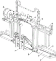
Fig. 1 is a schematic perspective view of the present invention.
Fig. 2 is a schematic perspective view of the driving assembly of the present invention.
Fig. 3 is a schematic perspective view of the winding assembly of the present invention.
Fig. 4 is a schematic perspective view of the compressing assembly of the present invention.
Fig. 5 is a perspective view of the removing assembly of the present invention.
Fig. 6 is a schematic perspective view of the spacing assembly of the present invention.
Fig. 7 is a perspective view of the cutting assembly of the present invention.
Reference numerals: 1. base, 2, guide rod, 3, screw rod, 4, driving component, 41, support plate, 42, guide ring, 43, support, 44, speed reducing motor, 45, rotating shaft, 5, winding component, 51, winding drum, 52, plug block, 53, first fixing rod, 54, first spring, 6, pressing component, 61, vertical rod, 62, pressing rod, 63, second spring, 64, special-shaped rod, 7, taking-out component, 71, mounting plate, 72, the rotary rod, 73, the belt pulley combination, 74, the ratchet wheel, 75, the right-angle frame, 76, the connecting rod, 77, the right-angle block, 78, the third spring, 79, the connecting plate, 710, the fourth spring, 711, the ratchet bar, 8, the limiting component, 81, the sliding block, 82, the limiting plate, 83, the clamping rod, 84, the clamping groove, 9, the cutting component, 91, the supporting rod, 92, the guide frame, 93, the second fixing rod, 94, the cutter, 95 and the fifth spring.
Detailed Description
The technical solutions in the embodiments of the present invention will be clearly and completely described below with reference to the drawings in the embodiments of the present invention, and it is obvious that the described embodiments are only a part of the embodiments of the present invention, and not all of the embodiments. All other embodiments, which can be derived by a person skilled in the art from the embodiments given herein without making any creative effort, shall fall within the protection scope of the present invention.
Example 1
A glass fiber product furling device convenient to fix is shown in figures 1-7 and comprises a base 1, guide rods 2, a lead screw 3, a driving assembly 4 and a furling assembly 5, wherein the left portion and the right portion of the base 1 are respectively provided with the two guide rods 2, the base 1 is rotatably provided with the lead screw 3, the guide rods 2 are provided with the driving assembly 4 driven in a rotating mode, and the driving assembly 4 is provided with the furling assembly 5.
When using the device, the staff puts the fine goods one end of glass that will carry out the roll-up to rolling component 5 on fixed, puts the back, drives rolling component 5 through drive assembly 4 and rotates the fine goods of glass and roll-up.
As shown in fig. 1, 2, 3, 4 and 5, the guide device includes a support plate 41, a guide ring 42, a bracket 43, a speed reduction motor 44 and a rotating shaft 45, the support plate 41 is slidably disposed between two guide rods 2, the support plate 41 is matched with the screw rod 3, the guide ring 42 is disposed on the upper portion of the support plate 41, the bracket 43 is disposed on the support plate 41 on the left portion, the speed reduction motor 44 is fixedly connected to the bracket 43 through a bolt, the rotating shaft 45 is rotatably disposed on the upper portion of the support plate 41 on the left portion, and the rotating shaft 45 is connected to an output shaft of the speed reduction motor 44.
When rolling up glass fiber product, the staff starts gear motor 44 and rotates, gear motor 44 rotates and drives pivot 45 and rotate, pivot 45 rotates and drives rolling subassembly 5 and rotate and roll up glass fiber product, the back is accomplished in the rolling, the staff closes gear motor 44, afterwards, the staff promotes backup pad 41 and slides dorsad on guide bar 2, and then drive the guide ring 42 and remove the glass fiber product of good roll-up dorsad and take off, so, can provide power when rolling up glass fiber product.
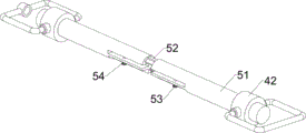
As shown in fig. 1 and 3, the winding assembly 5 includes winding drums 51, insertion blocks 52, first fixing rods 53 and first springs 54, the winding drums 51 are rotatably disposed in the guide rings 42, one of the winding drums 51 is provided with the insertion block 52, the insertion block 52 is slidably engaged with the other winding drum 51, the winding drums 51 are slidably provided with the first fixing rods 53, and the first springs 54 are wound between the first fixing rods 53 and the winding drums 51.
When rolling up glass fiber product, the staff stimulates first dead lever 53 and outwards slides on winding drum 51, first spring 54 is stretched, afterwards, the glass fiber product one end that the staff need roll up is put to between first dead lever 53 and winding drum 51, put the back, the staff loosens first dead lever 53, under the effect that first spring 54 resets, first dead lever 53 slides inwards along with it and fixes glass fiber product, after fixing, pivot 45 rotates the winding drum 51 that drives the left part and rotates, and then drive the winding drum 51 of right part through inserting block 52 and rotate and roll up glass fiber product, so, can roll up glass fiber product.
Example 2
On the basis of the embodiment 1, as shown in fig. 1 and 4, the pressing device further comprises a pressing assembly 6, the pressing assembly 6 comprises a vertical rod 61, a pressing rod 62, a second spring 63 and a special-shaped rod 64, the vertical rods 61 are arranged on the guide rings 42, the pressing rods 62 are arranged on the vertical rods 61 in a sliding manner, the second springs 63 are wound between the pressing rods 62 and the vertical rods 61, and the special-shaped rods 64 are arranged at the tops of the vertical rods 61.
When rolling up glass fiber product, when glass fiber product roll-up to a certain extent, glass fiber product promoted depression bar 62 and upwards slided on montant 61, and second spring 63 is compressed, so, can compress tightly glass fiber product when rolling up glass fiber product.
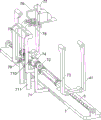
On the basis of embodiment 1, as shown in fig. 1 and 5, the taking-out device 7 further comprises a taking-out assembly 7, the taking-out assembly 7 comprises a mounting plate 71, a rotating rod 72, a pulley combination 73, a ratchet gear 74, a right-angle frame 75, a connecting rod 76, a right-angle block 77, a third spring 78, a connecting plate 79, a fourth spring 710 and a ratchet rack 711, the mounting plate 71 is arranged on the front side of the base 1, the rotating rod 72 is rotatably arranged on the mounting plate 71, the pulley combination 73 is connected between the left and right parts of the rotating rod 72 and the screw rod 3, the pulley combination 73 is composed of two pulleys and a flat belt, the rotating rod 72 is provided with one pulley, the screw rod 3 is provided with another pulley, the flat belt is wound between the two pulleys, the rotating rod 72 is provided with two ratchet gears 74, the frame 75 is slidably arranged on the upper part of the mounting plate 71, the two connecting rods 76 are slidably arranged on the right-angle frame 75, the connecting rod 76 is provided with the right-angle block 77, the right-angle block 77 is matched with the pressure lever 62, the right-angle block 77 is matched with the special-shaped lever 64, the third spring 78 is wound between the connecting rod 76 and the right-angle frame 75, the lower portion of the right-angle frame 75 is provided with the sliding connecting plate 79, the fourth spring 710 is connected between the connecting plate 79 and the right-angle frame 75, the left portion and the right portion of the connecting plate 79 are provided with the ratchet bars 711, and the ratchet bars 711 are matched with the ratchet gears 74.
When the glass fiber product is rolled up, the press rod 62 slides upwards to push the right-angle block 77 to move upwards, the right-angle block 77 moves upwards to drive the right-angle frame 75 to slide upwards through the connecting rod 76, the right-angle frame 75 slides upwards to drive the ratchet rack 711 to move upwards through the connecting plate 79, when the ratchet rack 711 moves upwards to be in contact with the ratchet wheel 74, the ratchet rack 711 moves forwards, the connecting plate 79 drives the ratchet rack 79 to move forwards to slide forwards on the right-angle frame 75, the fourth spring 710 is compressed, when the ratchet rack 711 moves upwards to be separated from the ratchet wheel 74, under the action of the reset of the fourth spring 710, the connecting plate 79 drives the ratchet rack 711 to move backwards to reset, when the right-angle block 77 moves upwards to be in contact with the special-shaped rod 64, the special-shaped rod 64 pushes the right-angle block 77 to move forwards to be separated from the press rod 62, the right-angle block 77 moves forwards to drive the connecting rod 76 to slide forwards on the right-angle frame 75, the third spring 78 is compressed, at this time, under the action of gravity, the right-angle frame 75 slides downwards along with the third spring, the right-angle frame 75 slides downwards to drive the ratchet rack 711 to move downwards through the connecting plate 79, the ratchet rack 711 moves downwards to drive the rotating rod 72 to rotate through the ratchet gear 74, the rotating rod 72 rotates to drive the screw rod 3 to rotate through the belt pulley combination 73, the screw rod 3 rotates to drive the supporting plate 41 to slide backwards, the right-angle frame 75 slides downwards to drive the right-angle block 77 to move downwards to be separated from the special-shaped rod 64, and under the reset action of the third spring 78, the connecting rod 76 drives the right-angle block 77 to move backwards to reset, so that the glass fiber product can be automatically loosened when the glass fiber product is wound to a certain degree.
On embodiment 1's basis, as shown in fig. 1 and 6, still including spacing subassembly 8, spacing subassembly 8 is including slider 81, limiting plate 82 and kelly 83, and the anterior left and right sides of base 1 all slidingtype is equipped with slider 81, all is equipped with limiting plate 82 on the slider 81, and limiting plate 82 all with a winding drum 51 sliding connection, and limiting plate 82 lower part all slidingtype is equipped with kelly 83, and the base 1 is all opened a row of draw-in groove 84 in the left and right sides, and draw-in groove 84 all cooperates with kelly 83.
When rolling up glass fiber product, the staff stimulates kelly 83 and upwards slides on limiting plate 82 and no longer blocks draw-in groove 84, afterwards, remove to suitable position about the size promotion limiting plate 82 according to glass fiber product, slider 81 slides left and right along with it, the back is accomplished, the staff promotes kelly 83 and slides down and block into draw-in groove 84, after the roll-up was accomplished, guide ring 42 drives and receives the reel 51 and move dorsad, at this moment, limiting plate 82 blocks the both ends that glass fiber product rolled up, so, can more make things convenient for people to take off the glass fiber product that the roll-up was good.
On the basis of embodiment 1, as shown in fig. 1 and 7, the cutting device further comprises a cutting assembly 9, the cutting assembly 9 comprises a supporting rod 91, a guide frame 92, a second fixing rod 93, a cutter 94 and a fifth spring 95, the supporting rods 91 are arranged on the left side and the right side of the rear portion of the base 1, the guide frame 92 is arranged between the tops of the two supporting rods 91, the second fixing rods 93 are arranged on the left side and the right side of the guide frame 92, the cutter 94 is arranged between the left second fixing rod 93 and the right second fixing rod 93 in a sliding manner, and the fifth spring 95 is wound between the second fixing rods 93 and the cutter 94.
When the glass fiber product is rolled up, the staff penetrates the guide frame 92 to wind the one end of the glass fiber product on the rolling barrel 51, after the rolling is completed, the staff pushes the cutter 94 to slide downwards on the second fixing rod 93 to cut off the glass fiber product, the fifth spring 95 is stretched, after the cutting, the staff loosens the cutter 94, and under the reset effect of the fifth spring 95, the cutter 94 slides upwards to reset, so that the glass fiber product can be cut off after the rolling is completed.
The above examples are merely representative of preferred embodiments of the present invention, and the description thereof is more specific and detailed, but not to be construed as limiting the scope of the present invention. It should be noted that, for those skilled in the art, various changes, modifications and substitutions can be made without departing from the spirit of the present invention, and these are all within the scope of the present invention. Therefore, the protection scope of the present patent shall be subject to the appended claims.

Claims (8)

1. The utility model provides a convenient fixed fine goods roll-up equipment of glass, which comprises: a base (1); at least two guide rods (2) are arranged on the base (1); the screw rod (3) is rotatably arranged on the base (1); the driving assembly (4) is arranged on the guide rod (2) and is driven in a rotating mode; and the winding component (5) is arranged on the driving component (4).
2. A conveniently fixed fiberglass product winding apparatus as claimed in claim 1, wherein the driving assembly (4) comprises: the two support plates (41) are arranged and are arranged between the two guide rods (2) in a sliding manner, and the support plates (41) are matched with the screw rod (3); two guide rings (42), wherein the two guide rings (42) are arranged on the support plate (41); a bracket (43) mounted on the support plate (41); a reduction motor (44) mounted on the bracket (43); and the rotating shaft (45) is rotatably arranged on the supporting plate (41), and the rotating shaft (45) is connected with an output shaft of the speed reducing motor (44).
3. A glass fiber product winding device convenient for fixing according to claim 2, wherein the winding assembly (5) comprises: two winding drums (51), wherein the two winding drums (51) are rotatably arranged on the guide ring (42), the inserting block (52) is arranged on the winding drums (51), and the inserting block (52) is in sliding fit with the other winding drum (51); two first fixing rods (53), wherein the two first fixing rods (53) are arranged on the winding drum (51) in a sliding manner; the number of the first springs (54) is two, and the two first springs (54) are installed between the first fixing rod (53) and the winding drum (51).
4. A glass fiber product furling apparatus convenient for fixing according to claim 3, characterized in that, it further comprises a pressing component (6), the pressing component (6) comprises: two vertical rods (61), wherein the two vertical rods (61) are arranged on the guide ring (42); two pressure levers (62), all install second spring (63) on montant (61) slidably, two second springs (63), all install between pressure lever (62) and montant (61); the number of the special-shaped rods (64) is two, and the two special-shaped rods (64) are both arranged on the vertical rod (61).
5. A glass fiber product furling apparatus convenient for fixing according to claim 4, characterized in that, it further comprises a take-out component (7), the take-out component (7) comprises: a mounting plate (71) mounted on the base (1); a rotating rod (72) rotatably mounted on the mounting plate (71); the two belt pulley combinations (73) are respectively arranged between the rotating rod (72) and the screw rod (3), the belt pulley combination (73) consists of two belt pulleys and a flat belt, one belt pulley is arranged on the rotating rod (72), the other belt pulley is arranged on the screw rod (3), and the flat belt is wound between the two belt pulleys; two ratchet gears (74) are arranged on the rotating rod (72); the right-angle frame (75) is slidably mounted on the mounting plate (71); two connecting rods (76), wherein the two connecting rods (76) are arranged on the right-angle frame (75) in a sliding manner; the two right angle blocks (77) are respectively arranged on the connecting rod (76), the right angle blocks (77) are respectively matched with the pressure rod (62), and the right angle blocks (77) are respectively matched with the special-shaped rod (64); two third springs (78), wherein the two third springs (78) are respectively arranged between the connecting rod (76) and the right-angle frame (75); the connecting plate (79) is arranged on the right-angle frame (75) in a sliding manner; the fourth spring (710) is arranged between the connecting plate (79) and the right-angle frame (75); the two ratchet racks (711) are arranged on the connecting plate (79), and the ratchet racks (711) are matched with the ratchet gear (74).
6. A glass fiber product furling equipment convenient for fixing according to claim 5, characterized in that it further comprises a spacing component (8), the spacing component (8) comprises: two sliding blocks (81), wherein the two sliding blocks (81) are arranged on the base (1) in a sliding manner; two limiting plates (82), wherein the two limiting plates (82) are respectively arranged on the sliding block (81), and the limiting plates (82) are respectively connected with the winding drum (51) in a sliding manner; the two clamping rods (83) are arranged on the limiting plate (82) in a sliding mode, at least two clamping grooves (84) are formed in the base (1), and the clamping grooves (84) are matched with the clamping rods (83).
7. A conveniently fixed fiberglass product winding apparatus as claimed in claim 6, further comprising a cutting assembly (9), wherein the cutting assembly (9) comprises: two support rods (91), wherein the two support rods (91) are arranged on the base (1); a guide frame (92) installed between the two support rods (91); two second fixing rods (93), wherein the two second fixing rods (93) are arranged on the guide frame (92); a cutter (94) slidably mounted between the two second fixing bars (93); and two fifth springs (95) are arranged between the second fixing rod (93) and the cutter (94).
8. The glass fiber product furling equipment convenient to fix as claimed in claim 7, characterized by further comprising a supporting plate (41), wherein the supporting plate (41) is U-shaped.
CN202111002874.7A 2021-08-30 2021-08-30 A convenient and fixed fiberglass product winding equipment Active CN113753629B (en)

Priority Applications (1)

Application Number Priority Date Filing Date Title
CN202111002874.7A CN113753629B (en) 2021-08-30 2021-08-30 A convenient and fixed fiberglass product winding equipment

Applications Claiming Priority (1)

Application Number Priority Date Filing Date Title
CN202111002874.7A CN113753629B (en) 2021-08-30 2021-08-30 A convenient and fixed fiberglass product winding equipment

Publications (2)

Publication Number Publication Date
CN113753629A true CN113753629A (en) 2021-12-07
CN113753629B CN113753629B (en) 2023-12-12

Family

ID=78791741

Family Applications (1)

Application Number Title Priority Date Filing Date
CN202111002874.7A Active CN113753629B (en) 2021-08-30 2021-08-30 A convenient and fixed fiberglass product winding equipment

Country Status (1)

Country Link
CN (1) CN113753629B (en)

Cited By (1)

* Cited by examiner, † Cited by third party
Publication number Priority date Publication date Assignee Title
CN115571681A (en) * 2022-11-01 2023-01-06 森织汽车内饰(武汉)有限公司 Calico fabric ration winding mechanism

Citations (8)

* Cited by examiner, † Cited by third party
Publication number Priority date Publication date Assignee Title
CN210709888U (en) * 2019-10-30 2020-06-09 江苏云锋塑料制品有限公司 Curtain coating film take-up device
CN211393404U (en) * 2019-11-11 2020-09-01 绍兴如多纺织有限公司 Cloth coiling mechanism for textile production
CN211769227U (en) * 2020-03-04 2020-10-27 昆山贝名新材料科技有限公司 A winding device for producing environmentally friendly glass fiber filter materials
KR102181314B1 (en) * 2019-05-15 2020-11-20 주식회사 와이아이이엔지 Cutting apparatus for glass fiber rebar
CN212503340U (en) * 2020-06-23 2021-02-09 河南省黄河防爆起重机有限公司 Automatic winding device for cable drum of crane
CN112723290A (en) * 2021-01-20 2021-04-30 南京浩道然贸易有限公司 Epoxy coating filling device
CN213568684U (en) * 2020-07-24 2021-06-29 青岛海之霖建材科技有限公司 A receiving agencies for pitch waterproofing membrane production line
CN113071944A (en) * 2021-03-05 2021-07-06 南京红橙黄商贸有限公司 New material film's rolling cutting device

Patent Citations (8)

* Cited by examiner, † Cited by third party
Publication number Priority date Publication date Assignee Title
KR102181314B1 (en) * 2019-05-15 2020-11-20 주식회사 와이아이이엔지 Cutting apparatus for glass fiber rebar
CN210709888U (en) * 2019-10-30 2020-06-09 江苏云锋塑料制品有限公司 Curtain coating film take-up device
CN211393404U (en) * 2019-11-11 2020-09-01 绍兴如多纺织有限公司 Cloth coiling mechanism for textile production
CN211769227U (en) * 2020-03-04 2020-10-27 昆山贝名新材料科技有限公司 A winding device for producing environmentally friendly glass fiber filter materials
CN212503340U (en) * 2020-06-23 2021-02-09 河南省黄河防爆起重机有限公司 Automatic winding device for cable drum of crane
CN213568684U (en) * 2020-07-24 2021-06-29 青岛海之霖建材科技有限公司 A receiving agencies for pitch waterproofing membrane production line
CN112723290A (en) * 2021-01-20 2021-04-30 南京浩道然贸易有限公司 Epoxy coating filling device
CN113071944A (en) * 2021-03-05 2021-07-06 南京红橙黄商贸有限公司 New material film's rolling cutting device

Cited By (1)

* Cited by examiner, † Cited by third party
Publication number Priority date Publication date Assignee Title
CN115571681A (en) * 2022-11-01 2023-01-06 森织汽车内饰(武汉)有限公司 Calico fabric ration winding mechanism

Also Published As

Publication number Publication date
CN113753629B (en) 2023-12-12

Similar Documents

Publication Publication Date Title
CN211311974U (en) Carbon cloth cuts uses location fixing device
CN113071944B (en) Rolling cutting device of new material film
CN114009481B (en) Sectional cutting equipment for frozen meat products for kitchen
CN218079641U (en) Flattening mechanism for photovoltaic solder strip
CN113753629B (en) A convenient and fixed fiberglass product winding equipment
CN221521507U (en) Automatic deviation correcting device for rolling PET film
CN118163161B (en) Yoga mat production edging equipment
CN219450236U (en) Cutting device of cloth cutting machine
CN219972790U (en) Shoulder belt cutting device for underwear processing
CN217290614U (en) C-shaped steel cutting machine with port rolling mechanism
CN208245960U (en) It is a kind of to facilitate the bearing shell processing sheet metal slicing device for adjusting guiding plate spacing
CN222344778U (en) Cutting all-in-one is cut with cutting open to steel processing
CN223510198U (en) A cutting device for environmentally friendly textile fabric production
CN222569413U (en) Blanking mechanism of plate shearing machine
CN221563600U (en) Double-sided glass laminating machine suitable for multiple dimensions
CN221873193U (en) A film coating device for automobile decorative panel
CN222494469U (en) Automatic self-adhesive label waste discharge device
CN223493361U (en) Braided rope belt cutting device
CN220007934U (en) Cutting and finishing device for pulp paper production
CN221717132U (en) A special cutting device for anti-bubble non-substrate adhesive protective film of OLED display screen
CN112310894A (en) Waste power cable sheath peeling device
CN117885168B (en) A four-roller bamboo veneer cutting machine
CN217495394U (en) Flat-opening machine for processing food-grade environment-friendly plastic bag
CN221562252U (en) Laminating machine tectorial membrane device
CN223558496U (en) PVC vacuum film cutting device

Legal Events

Date Code Title Description
PB01 Publication
PB01 Publication
SE01 Entry into force of request for substantive examination
TA01 Transfer of patent application right

Effective date of registration: 20231110

Address after: 221000 Industrial Building 01, Zone A, Jianglong Road 22-2, Peibei Economic Development Zone, Yangtun Town, Peixian County, Xuzhou City, Jiangsu Province

Applicant after: Jiangsu zhufangren Intelligent Manufacturing Co.,Ltd.

Address before: 518110 Room 501, building 21, Hekeda Industrial Park, No. 294, Huarong Road, Langkou community, Dalang street, Longhua District, Shenzhen, Guangdong Province

Applicant before: Li Yahui

GR01 Patent grant
GR01 Patent grant
TR01 Transfer of patent right

Effective date of registration: 20250916

Address after: 522000 Xichang Town Xidong Village Dawei Shixiang, Jiedong County, Jieyang City, Guangdong Province

Patentee after: Lin Aishan

Country or region after: China

Address before: 221000 Industrial Building 01, Zone A, Jianglong Road 22-2, Peibei Economic Development Zone, Yangtun Town, Peixian County, Xuzhou City, Jiangsu Province

Patentee before: Jiangsu zhufangren Intelligent Manufacturing Co.,Ltd.

Country or region before: China

TR01 Transfer of patent right

Effective date of registration: 20251126

Address after: 130000 No. 333, Ta tou Road, Chaoyang economic development zone, Changchun City, Jilin Province

Patentee after: Changchun Huida Auto Parts Manufacturing Co.,Ltd.

Country or region after: China

Address before: 522000 Xichang Town Xidong Village Dawei Shixiang, Jiedong County, Jieyang City, Guangdong Province

Patentee before: Lin Aishan

Country or region before: China