Disclosure of Invention
The present invention is directed to solving at least one of the problems of the prior art. Therefore, the invention provides a steel plate printing machine which can meet the requirement of pad printing on a curved surface to-be-printed piece under the condition of small occupied space, can meet the printing requirement of large-area patterns under the condition of small occupied space and is convenient for automatic pad printing work.
An embodiment of a first aspect of the invention provides a steel plate printing press comprising: a machine platform; the convex printing table is arranged on the machine table, is used for bearing a printed piece and can move on the machine table; the oil cup steel plate module is arranged on the machine table and can move on the machine table; the oil cup steel plate module comprises a printing steel plate and an oil cup, the printing steel plate is etched with a pattern to be printed, and the oil cup is used for coating ink on the printing steel plate; the pad printing module is arranged on the machine table and comprises a printing device, a first driving device and a second driving device, the printing device comprises a printing belt and a printing driving structure, the printing driving structure is used for driving the printing belt to rotate in a reciprocating mode, the first driving device is used for driving the printing device to move up and down, the second driving device is used for driving the printing device to move in a direction parallel to the length direction of a printing steel plate, and the printing belt is used for pad printing ink on the printing steel plate to a printing part on the convex printing table; the first transfer mechanism is arranged on the machine table and used for driving the convex printing table to move to the position below the printing device or to move away from the position below the printing device; and the second transfer mechanism is arranged on the machine table and used for driving the oil cup steel plate module to move to the lower part of the printing device or be far away from the lower part of the printing device.
According to the tensioning mechanism provided by the embodiment of the invention, at least the following technical effects are achieved:
the steel plate printing machine is provided with the pad printing module, the oil cup steel plate module and the convex printing table, the components can move mutually, and pad printing operation between the oil cup steel plate module and the convex printing table is realized through the pad printing module. And, printing device includes printing belt and printing drive structure, through the mutual motion between printing device and oil cup steel sheet module, the convex surface printing platform, with the bottom of printing belt and the printing steel sheet contact that the coating has printing ink, rotates printing belt and synchronous horizontal migration printing device, can shift the pattern on the printing steel sheet to on the printing belt. Further, through similar action, the printing belt with the pattern is moved to the convex surface printing table, the bottom of the printing belt is made to be in contact with the piece to be printed, the printing belt is rotated, the printing device is synchronously moved along the outline of the piece to be printed, and then the pattern on the printing belt can be transferred to the piece to be printed. Through so setting up, can realize the bat printing operation of large tracts of land pattern through flexible printing belt, thereby avoid using the printing steel sheet of the rigidity of large tracts of land to lead to the problem that occupation space is big.
According to some embodiments of the invention, the printing device further comprises a gantry arranged on the machine table, and the printing device, the first driving device and the second driving device are arranged on the gantry.
According to some embodiments of the invention, the printing machine further comprises a first guide rail, the first guide rail is arranged on the machine table and penetrates through the lower part of the portal frame, and the convex printing table and the oil cup steel plate module are both connected to the first guide rail in a sliding manner and respectively move through the first transfer mechanism and the second transfer mechanism.
According to some embodiments of the invention, further comprising: the second guide rail is arranged on the portal frame and is parallel to the printing steel plate; the first driving device comprises a horizontal sliding table and a first driver, the horizontal sliding table is connected to the second guide rail in a sliding mode, and the first driver is used for driving the horizontal sliding table to slide along the second guide rail; the third guide rail is arranged on the horizontal sliding table along the vertical direction; the second driving device comprises a lifting frame and a second driver, the lifting frame is connected to the third guide rail in a sliding mode, and the second driver is used for driving the lifting frame to slide along the third guide rail; printing device sets up on lift slip table.
According to some embodiments of the invention, the printing apparatus further comprises a tensioning mechanism, the tensioning mechanism comprising: a drive rod; two driving arms, wherein first ends of the two driving arms are respectively connected to the driving rod, and the first ends can move along the driving rod; the second ends of the two driving arms are connected to the tensioning member; when the two first ends move towards each other, the tensioning piece can move in the direction away from the driving rod under the pushing of the second end, and the tensioning piece is abutted to the printing belt to tension the printing belt.
According to some embodiments of the invention, the tensioning mechanism further comprises: one end of each first connecting piece is sleeved on the driving rod and can move along the driving rod, and the other end of each first connecting piece is connected with the corresponding first end; the two second connecting pieces are in threaded connection with the driving rod and are respectively connected with the two first connecting pieces through springs; the second connecting pieces and the threads connected with the driving rod are opposite in direction, the driving rod is rotated, the second connecting pieces can move in opposite directions or in opposite directions, and then the first connecting pieces are driven to move in opposite directions or in opposite directions.
According to some embodiments of the invention, the ink cup steel plate module further comprises an ink cup driving structure and a fourth guide rail, the fourth guide rail being arranged in parallel with the printing steel plate, the ink cup driving structure comprising: the driving part is connected to the fourth guide rail in a sliding mode and driven by the air cylinder to move on the fourth guide rail; the pushing part is connected with the oil cup and used for driving the oil cup to move on the printing steel plate; and the two ends of the connecting part are respectively connected with the driving part and the pushing part.
According to some embodiments of the invention, the pushing part is a circular ring piece, and the oil cup is arranged in the middle of the circular ring piece and can be driven by the circular ring piece.
According to some embodiments of the invention, the machine platform is provided with a steel plate placing groove, and the printing steel plate is detachably arranged in the steel plate placing groove.
According to some embodiments of the invention, further comprising a cleaning device, the cleaning device comprising: the cleaning frame is arranged on the machine table; the raw material roller is arranged on the cleaning frame; the cleaning roller is arranged on the cleaning frame; the recovery roller is arranged on the cleaning frame; the raw material roller, the cleaning roller and the recovery roller are connected through a raw material dipping film.
Additional aspects and advantages of the invention will be set forth in part in the description which follows and, in part, will be obvious from the description, or may be learned by practice of the invention.
Detailed Description
Reference will now be made in detail to embodiments of the present invention, examples of which are illustrated in the accompanying drawings, wherein like or similar reference numerals refer to the same or similar elements or elements having the same or similar function throughout. The embodiments described below with reference to the accompanying drawings are illustrative only for the purpose of explaining the present invention, and are not to be construed as limiting the present invention.
In the description of the present invention, it is to be understood that the positional or positional relationships referred to in the positional descriptions, such as up, down, front, rear, left, right, etc., are based on the positional or positional relationships shown in the drawings, which are merely for convenience of description and simplification of description, and do not indicate or imply that the device or element referred to must have a particular orientation, be constructed and operated in a particular orientation, and thus, should not be construed as limiting the present invention.
In the description of the present invention, a plurality of means is two or more, and greater than, less than, more than, etc. are understood as excluding the present number, and greater than, less than, etc. are understood as including the present number. If the first and second are described for the purpose of distinguishing technical features, they are not to be understood as indicating or implying relative importance or implicitly indicating the number of technical features indicated or implicitly indicating the precedence of the technical features indicated.
In the description of the present invention, unless otherwise explicitly defined, terms such as arrangement, installation, connection and the like should be broadly construed, and those skilled in the art can reasonably determine the specific meanings of the above terms in the present invention in combination with the detailed contents of the technical solutions.
A steel plate printing machine according to an embodiment of the present invention is described below with reference to fig. 1 to 7.
Referring to fig. 1 to 3, fig. 1 to 3 show a steel plate printing machine according to an embodiment of the present invention, including: a machine table 500; the convex printing table 300 is arranged on the machine table 500, is used for bearing a printed piece, and can move on the machine table 500; the oil cup steel plate module 200 is arranged on the machine table 500 and can move on the machine table 500; the oil cup steel plate module 200 comprises a printing steel plate 220 and an oil cup 210, the printing steel plate 220 is etched with patterns to be printed, and the oil cup 210 is used for coating ink on the printing steel plate 220; the pad printing module is arranged on the machine table 500, and comprises a printing device 100, a first driving device 620 and a second driving device 622, wherein the printing device 100 comprises a printing belt 130 and a printing driving structure 110, the printing driving structure 110 is used for driving the printing belt 130 to rotate in a reciprocating manner, the first driving device 620 is used for driving the printing device 100 to move up and down, the second driving device 622 is used for driving the printing device 100 to move in a direction parallel to the length direction of the printing steel plate 220, and the printing belt 130 is used for pad printing ink on the printing steel plate 220 to a printing part on the convex printing table 300; a first transfer mechanism disposed on the machine 500 for driving the convex printing platform 300 to move to a position below the printing device 100 or to move away from the position below the printing device 100; the second transfer mechanism is disposed on the machine 500, and configured to drive the oil cup steel plate module 200 to move to the lower side of the printing device 100, or move away from the lower side of the printing device 100.
The steel plate printing machine is provided with a pad printing module, an ink cup steel plate module 200 and a convex surface printing table 300, the components can move mutually, and pad printing operation between the ink cup steel plate module 200 and the convex surface printing table 300 is realized through the pad printing module. Moreover, the printing device 100 comprises a printing belt 130 and a printing driving structure 110, and by means of the mutual movement between the printing device 100, the ink cup steel plate module 200 and the convex printing table 300, the bottom of the printing belt 130 is in contact with the printing steel plate 220 coated with ink, the printing belt 130 is rotated, and the printing device 100 is synchronously and horizontally moved, so that the pattern on the printing steel plate 220 can be transferred onto the printing belt 130. Further, by moving the printing belt 130 with the pattern to the convex printing station 300 and contacting the bottom of the printing belt 130 with the member to be printed, the pattern on the printing belt 130 can be transferred to the member to be printed by rotating the printing belt 130 and synchronously moving the printing apparatus 100 along the contour of the member to be printed. With this arrangement, a large-area pattern transfer operation can be performed by the flexible printing belt 100, and a problem of a large occupied space due to the use of a large-area rigid printing steel plate 220 can be avoided. It is understood that the printing table may be either a convex printing table 300 or a flat printing table, and that the pad printing operation may be performed by the above-described method.
Referring to fig. 1 and 2, in some embodiments, the steel plate printing machine further includes a gantry 600 disposed on the machine table 500, and the printing device 100, the first driving device 620, and the second driving device 622 are disposed on the gantry 600.
The gantry 600 is erected above the machine 500, so that the printing device 100 is arranged above the machine 500 and can move on the gantry 600 along a vertical direction or a direction parallel to the printing steel plate 220. Meanwhile, the requirement that other components can pass through the bottom of the portal frame 600 is facilitated. Similarly, the printing device 100 may be suspended above the machine 500 and not connected to the machine 500.
Referring to fig. 1 and 2, in some embodiments, the sheet-fed printing press further includes a first guide rail 510, the first guide rail 510 is disposed on the machine 500 and passes through the lower portion of the gantry 600, and the convex printing table 300 and the ink cup sheet module 200 are both slidably connected to the first guide rail 510 and are moved by a first transfer mechanism and a second transfer mechanism, respectively.
By providing the first transfer mechanism and the second transfer mechanism, the convex printing platform 300 and the oil cup steel plate module 200 can slide on the machine platform 500 along the first guide rail 510, and the printing device 100 can also move on the portal frame 600 through the first driving device 620 and the second driving device 622. It should be understood that cylinders may be provided to drive the convex printing table 300, the ink cup plate module 200, and the printing apparatus 100 to move, or manually to adjust the positions. In addition, the driving method may also adopt other driving devices, and is not limited thereto.
Referring to fig. 1, further, the steel plate printing machine further includes: a second guide rail 610 disposed on the gantry 600 and parallel to the printing steel plate 220; the first driving device 620 comprises a horizontal sliding table and a first driver, the horizontal sliding table is connected to the second guide rail in a sliding manner, and the first driver is used for driving the horizontal sliding table to slide along the second guide rail; a third guide rail 621 provided on the horizontal sliding table in the vertical direction; the second driving device 622 comprises a lifting frame and a second driver, the lifting frame is connected to the third guide rail 621 in a sliding manner, and the second driver is used for driving the lifting frame to slide along the third guide rail; the printing device 100 is disposed on the elevating slide table.
In some embodiments, a motor screw driver is disposed between the first driver and the second driver, and is used to drive the horizontal sliding table and the lifting frame to move along the second guide rail 610 and the third guide rail 621 respectively.
It can be understood that, referring to fig. 1, in this structure, a second guide rail 610 is formed on the gantry 600, the horizontal sliding table in the first driving device 620 is slidably connected to the second guide rail 610, and the horizontal sliding table is driven by the first driver. Also, in some embodiments, the horizontal sliding table has a plate structure for disposing the third guide rail 621, and the second guide rail 610 has two pieces, which are disposed corresponding to the upper and lower sides of the horizontal sliding table, respectively, so that the first driving device 620 can move more stably. Further, a third guide rail 621 is provided on the horizontal sliding table so as to be movable in a direction parallel to the printing steel plate 220 with the first driving device 620. The third guide rail 621 is perpendicular to the second guide rail 610, the lifting frame is slidably connected to the third guide rail 621, and the lifting frame is also connected to the printing device 100, so that the printing device 100 can move in the vertical direction along the third guide rail 621. By doing so, the printing apparatus 100 can move in the vertical direction or the horizontal direction (the direction parallel to the printing steel plate 220) on the gantry 600.
Referring to fig. 3 and 4, in some embodiments, the printing device 100 further includes a tensioning mechanism 110, and the tensioning mechanism 110 includes: a drive rod 122; two driving arms 123, first ends 1231 of the two driving arms 123 are respectively connected to the driving rod 122, and the first ends 1231 are capable of moving along the driving rod 122; a tensioning member 124, the second ends 1232 of both drive arms 123 being connected to the tensioning member 124; when the first ends 1231 move toward each other, the tensioning member 124 can move away from the driving rod 122 under the pushing of the second end 1232, and the tensioning member 124 abuts against the printing belt 130 to tension the printing belt 130. Referring to fig. 1 and 3, the printing apparatus 100 further includes a housing, and the printing belt 130 and other members are disposed inside the housing, and when the printing apparatus 100 needs to be operated, the housing is removed to expose the printing belt 130.
It will be appreciated that the first end 1231 is rotatably connected to the driving rod 122, the second end 1232 is rotatably connected to the tensioning member 124, so that the two driving arms 123 can swing between the driving rod 122 and the tensioning member 124, and the second end 1232 and the tensioning member 124 can move away from or close to the driving rod 122, so as to adjust the tensioning degree of the printing belt 130 by the tensioning mechanism 110.
By connecting the first ends 1231 of the driving arms 123 to the two ends of the driving rod 122 respectively, the second ends 1232 of the driving arms 123 are both connected to the tensioning member 124, and at this time, the tensioning member 124, the two driving arms 123 and the driving rod 122 form a triangle, and when the first ends 1231 of the two driving arms 123 move along the driving rod 122 in the opposite direction, the second ends 1232 extend in the direction away from the driving rod 122, so as to push the tensioning member 124 to move, and further push the printing belt 130 connected to the tensioning member 124 to tension the printing belt. When the first end 1231 is moved to a desired position, it can also be fixed by screws, thread structures, etc. to enable the tensioning mechanism 110 to perform the tensioning function.
It will also be appreciated that in some embodiments, a tensioner 121 may be provided in the tensioning member 124, with the tensioner 121 abutting the print belt 130, thereby tensioning the print belt 130. Further, the tension member 124 may further include a tension frame, the tension frame is provided with a rotation shaft 128, and the tension pulley 121 is also provided on the tension frame, and the rotation shaft 128 is rotatably connected to a frame body of the printing apparatus so that the tension pulley 121 can swing up and down and tension the printing belt 130.
Referring to fig. 4, in some embodiments, tensioning mechanism 110 further comprises: one end of the first connecting element 125 is sleeved on the driving rod 122 and can move along the driving rod 122, and the other ends of the two first connecting elements 125 are respectively connected to the two first ends 1231; two second connecting pieces 126, the second connecting pieces 126 are in threaded connection with the driving rod 122, and the two second connecting pieces 126 are respectively connected with the two first connecting pieces 125 through springs 127; the two second connecting members 126 are opposite to the thread direction of the driving rod 122, and the driving rod 122 is rotated to move the two second connecting members 126 toward or away from each other, so as to drive the two first connecting members 125 to move toward or away from each other.
Through such an arrangement, the tension degree of the tension mechanism 110 can be adjusted by rotating the driving rod 122, which is convenient. And, the second link 126 is connected with the first link 125 by a spring 127, and thus the first link 125 is moved by being elastically pushed to adjust the tension degree of the tension mechanism 110. By providing the spring 127, the first connecting member 125 is allowed to move along the driving rod 122 against the elastic force of the spring 127, i.e., when the belt tensioner 121 abuts against the member to be printed, so as to avoid the damage to the printing apparatus 100 or the member to be printed due to the over-rigidity of the tensioner mechanism 110.
Referring to fig. 1, 2, 5 and 6, in some embodiments, the ink cup plate module 200 further includes an ink cup drive structure 240 and a fourth guide rail 230, the fourth guide rail 230 being disposed parallel to the printing plate 220, the ink cup drive structure 240 including: a driving unit 243 slidably connected to the fourth rail 230 and driven by the cylinder to move on the fourth rail 230; the pushing part 241 is connected with the oil cup 210 and used for driving the oil cup 210 to move on the printing steel plate 220; and a connecting part having both ends connected to the driving part 243 and the pushing part 241, respectively.
Referring to fig. 5 and 6, in some embodiments, the pushing portion 241 is a circular ring, and the oil cup 210 is disposed in the middle of the circular ring and can be driven by the circular ring. The cylindrical oil cup 210 is driven to move by arranging the annular pushing part 241. Moreover, the circular ring piece is hollow and can be opened at the bottom of the oil cup 210, so that the printing ink can be coated on the printing steel plate 220.
After the pattern to be printed is etched on the printing steel plate 220, the ink cup driving structure 240 is arranged to move the ink cup 210, and the dye is uniformly coated on the printing steel plate 220, so that the transfer printing operation can be performed on the printing steel plate 220 through the printing device 100. In the ink cup driving structure 240, the driving portion 243 is driven by the cylinder to move on the fourth guide rail 230, and the pushing portion 241 can be driven by the driving portion 243 through the insulating portion, so that the ink cup 210 moves on the printing steel plate 220.
Referring to fig. 1, in some embodiments, a steel plate placing groove is formed on the machine 500, and the printing steel plate 220 is detachably disposed in the steel plate placing groove. Through so setting up to make printing steel sheet 200 can dismantle the setting on this steel sheet press, through changing printing steel sheet 200, alright quick replacement the pattern that this steel sheet press printed.
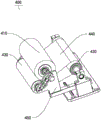
Referring to fig. 1 and 7, in some embodiments, the steel plate printing press further includes a cleaning device 400 including: a cleaning frame 450 disposed on the machine 500; the raw material roller 410 is arranged on the cleaning frame 450; a cleaning roller 420 disposed on the cleaning frame 450; a recovery roller 430 disposed on the cleaning frame 450; wherein the raw material roller 410, the cleaning roller 420 and the recovery roller 430 are connected through a raw material dipping film 440. When the printing belt 130 needs to be cleaned, the printing device 100 is moved to the cleaning device 400, the printing belt 130 is attached to the cleaning roller 420 to rotate, the raw material roller 410, the cleaning roller 420 and the recovery roller 430 are driven to rotate, the raw material dipping film 440 is moved to the cleaning roller 420 from the raw material roller 410, so that the raw material dipping film 440 can continuously wipe off the dye on the printing belt 130, the printing belt 130 is cleaned, and then the raw material dipping film 440 stuck with the dye is recovered by the recovery roller 430.
A steel plate printing machine according to an embodiment of the present invention will be described in detail with reference to fig. 1 to 7 as a specific embodiment. It is to be understood that the following description is only exemplary, and not a specific limitation of the invention.
A steel plate printing press comprising: a machine table 500; the convex printing table 300 is arranged on the machine table 500, is used for bearing a printed piece, and can move on the machine table 500; the oil cup steel plate module 200 is arranged on the machine table 500 and can move on the machine table 500; the oil cup steel plate module 200 comprises a printing steel plate 220 and an oil cup 210, the printing steel plate 220 is etched with patterns to be printed, and the oil cup 210 is used for coating ink on the printing steel plate 220; the pad printing module is arranged on the machine table 500, and comprises a printing device 100, a first driving device 620 and a second driving device 622, wherein the printing device 100 comprises a printing belt 130 and a printing driving structure 110, the printing driving structure 110 is used for driving the printing belt 130 to rotate in a reciprocating manner, the first driving device 620 is used for driving the printing device 100 to move up and down, the second driving device 622 is used for driving the printing device 100 to move in a direction parallel to the length direction of the printing steel plate 220, and the printing belt 130 is used for pad printing ink on the printing steel plate 220 to a printing part on the convex printing table 300; a first transfer mechanism disposed on the machine 500 for driving the convex printing platform 300 to move to a position below the printing device 100 or to move away from the position below the printing device 100; the second transfer mechanism is disposed on the machine 500, and configured to drive the oil cup steel plate module 200 to move to the lower side of the printing device 100, or move away from the lower side of the printing device 100. The steel plate printing machine further comprises a portal frame 600 arranged on the machine table 500, and the printing device 100, the first driving device 620 and the second driving device 622 are all arranged on the portal frame 600. The steel plate printing machine further comprises a first guide rail 510, the first guide rail 510 is arranged on the machine table 500 and penetrates through the lower portion of the portal frame 600, the convex printing table 300 and the oil cup steel plate module 200 are connected to the first guide rail 510 in a sliding mode and move through a first transfer mechanism and a second transfer mechanism respectively. The steel sheet printing press further includes: a second guide rail 610 disposed on the gantry 600 and parallel to the printing steel plate 220; the first driving device 620 comprises a horizontal sliding table and a first driver, the horizontal sliding table is connected to the second guide rail in a sliding manner, and the first driver is used for driving the horizontal sliding table to slide along the second guide rail; a third guide rail 621 provided on the horizontal sliding table in the vertical direction; the second driving device 622 comprises a lifting frame and a second driver, the lifting frame is connected to the third guide rail 621 in a sliding manner, and the second driver is used for driving the lifting frame to slide along the third guide rail; the printing device 100 is disposed on the elevating slide table. The printing apparatus 100 further includes a tensioning mechanism 110, and the tensioning mechanism 110 includes: a drive rod 122; two driving arms 123, first ends 1231 of the two driving arms 123 are respectively connected to the driving rod 122, and the first ends 1231 are capable of moving along the driving rod 122; a tensioning member 124, the second ends 1232 of both drive arms 123 being connected to the tensioning member 124; when the first ends 1231 move toward each other, the tensioning member 124 can move away from the driving rod 122 under the pushing of the second end 1232, and the tensioning member 124 abuts against the printing belt 130 to tension the printing belt 130. The tensioning mechanism 110 further comprises: one end of the first connecting element 125 is sleeved on the driving rod 122 and can move along the driving rod 122, and the other ends of the two first connecting elements 125 are respectively connected to the two first ends 1231; two second connecting pieces 126, the second connecting pieces 126 are in threaded connection with the driving rod 122, and the two second connecting pieces 126 are respectively connected with the two first connecting pieces 125 through springs 127; the two second connecting members 126 are opposite to the thread direction of the driving rod 122, and the driving rod 122 is rotated to move the two second connecting members 126 toward or away from each other, so as to drive the two first connecting members 125 to move toward or away from each other. Oil handleless cup steel sheet module 200 still includes oil handleless cup drive structure 240 and fourth guide rail 230, and fourth guide rail 230 and printing steel sheet 220 parallel arrangement, oil handleless cup drive structure 240 include: a driving unit 243 slidably connected to the fourth rail 230 and driven by the cylinder to move on the fourth rail 230; the pushing part 241 is connected with the oil cup 210 and used for driving the oil cup 210 to move on the printing steel plate 220; and a connecting part having both ends connected to the driving part 243 and the pushing part 241, respectively. The pushing portion 241 is a circular ring piece, and the oil cup 210 is arranged in the middle of the circular ring piece and can be driven by the circular ring piece. The machine table 500 is provided with a steel plate placing groove, and the printing steel plate 220 is detachably arranged in the steel plate placing groove. The steel plate printing machine further includes a cleaning apparatus 400, the cleaning apparatus 400 including: a cleaning frame 450 disposed on the machine 500; the raw material roller 410 is arranged on the cleaning frame 450; a cleaning roller 420 disposed on the cleaning frame 450; a recovery roller 430 disposed on the cleaning frame 450; wherein the raw material roller 410, the cleaning roller 420 and the recovery roller 430 are connected through a raw material dipping film 440.
According to the steel plate printing machine provided by the embodiment of the invention, at least some technical effects as follows can be achieved: the steel plate printing machine is provided with a pad printing module, an ink cup steel plate module 200 and a convex surface printing table 300, the components can move mutually, and pad printing operation between the ink cup steel plate module 200 and the convex surface printing table 300 is realized through the pad printing module. Moreover, the printing device 100 comprises a printing belt 130 and a printing driving structure 110, and by means of the mutual movement between the printing device 100, the ink cup steel plate module 200 and the convex printing table 300, the bottom of the printing belt 130 is in contact with the printing steel plate 220 coated with ink, the printing belt 130 is rotated, and the printing device 100 is synchronously and horizontally moved, so that the pattern on the printing steel plate 220 can be transferred onto the printing belt 130. Further, by moving the printing belt 130 with the pattern to the convex printing station 300 and contacting the bottom of the printing belt 130 with the member to be printed, the pattern on the printing belt 130 can be transferred to the member to be printed by rotating the printing belt 130 and synchronously moving the printing apparatus 100 along the contour of the member to be printed. With this arrangement, a large-area pattern transfer operation can be performed by the flexible printing belt 100, and a problem of a large occupied space due to the use of a large-area rigid printing steel plate 220 can be avoided. It is understood that the printing table may be either a convex printing table 300 or a flat printing table, and that the pad printing operation may be performed by the above-described method.
In the description herein, references to the description of the term "one embodiment," "some embodiments," "an illustrative embodiment," "an example," "a specific example," or "some examples" or the like mean that a particular feature, structure, material, or characteristic described in connection with the embodiment or example is included in at least one embodiment or example of the invention. In this specification, the schematic representations of the terms used above do not necessarily refer to the same embodiment or example. Furthermore, the particular features, structures, materials, or characteristics described may be combined in any suitable manner in any one or more embodiments or examples.
While embodiments of the present invention have been shown and described, it will be understood by those of ordinary skill in the art that: numerous changes, modifications, substitutions and alterations can be made to the embodiments without departing from the principles and spirit of the invention, the scope of which is defined by the claims and the equivalents.