CN113733161A - Quick interface device of end effector of mechanical arm - Google Patents

Quick interface device of end effector of mechanical arm Download PDF

Info

Publication number
CN113733161A
CN113733161A CN202111160224.5A CN202111160224A CN113733161A CN 113733161 A CN113733161 A CN 113733161A CN 202111160224 A CN202111160224 A CN 202111160224A CN 113733161 A CN113733161 A CN 113733161A
Authority
CN
China
Prior art keywords
locking
end effector
interface device
matching part
telescopic sleeve
Prior art date
Legal status (The legal status is an assumption and is not a legal conclusion. Google has not performed a legal analysis and makes no representation as to the accuracy of the status listed.)
Granted
Application number
CN202111160224.5A
Other languages
Chinese (zh)
Other versions
CN113733161B (en
Inventor
赵振昊
王昊
韩彬
郭东丽
苏亮
杨永彬
王威
金玮玮
Current Assignee (The listed assignees may be inaccurate. Google has not performed a legal analysis and makes no representation or warranty as to the accuracy of the list.)
Beijing Institute of Spacecraft System Engineering
Original Assignee
Beijing Institute of Spacecraft System Engineering
Priority date (The priority date is an assumption and is not a legal conclusion. Google has not performed a legal analysis and makes no representation as to the accuracy of the date listed.)
Filing date
Publication date
Application filed by Beijing Institute of Spacecraft System Engineering filed Critical Beijing Institute of Spacecraft System Engineering
Priority to CN202111160224.5A priority Critical patent/CN113733161B/en
Publication of CN113733161A publication Critical patent/CN113733161A/en
Application granted granted Critical
Publication of CN113733161B publication Critical patent/CN113733161B/en
Active legal-status Critical Current
Anticipated expiration legal-status Critical

Links

Images

Classifications

    • B—PERFORMING OPERATIONS; TRANSPORTING
    • B25—HAND TOOLS; PORTABLE POWER-DRIVEN TOOLS; MANIPULATORS
    • B25J—MANIPULATORS; CHAMBERS PROVIDED WITH MANIPULATION DEVICES
    • B25J19/00—Accessories fitted to manipulators, e.g. for monitoring, for viewing; Safety devices combined with or specially adapted for use in connection with manipulators
    • B—PERFORMING OPERATIONS; TRANSPORTING
    • B25—HAND TOOLS; PORTABLE POWER-DRIVEN TOOLS; MANIPULATORS
    • B25J—MANIPULATORS; CHAMBERS PROVIDED WITH MANIPULATION DEVICES
    • B25J18/00—Arms

Landscapes

  • Engineering & Computer Science (AREA)
  • Robotics (AREA)
  • Mechanical Engineering (AREA)
  • Manipulator (AREA)

Abstract

本申请提供了一种机械臂末端执行器快速接口装置,属于空间机械臂技术领域。本发明通过设置第一配合部、第二配合部和第三配合部,所述第一配合部安装在机械臂末端关节上,所述第二配合部安装在机械臂末端执行器上,第三配合部属于外部器械。只需第一配合部中的定位销和第二配合部中的定位孔对准连接,在第三配合部的拨动柱施加的外力作用下,带动锁定开关组件运动,使定位销插入定位孔,从而实现锁紧或者松脱的功能,即可做到快速、稳定、灵活地更换机械臂末端执行器。

Figure 202111160224

The present application provides a quick interface device for a manipulator end effector, which belongs to the technical field of space manipulators. In the present invention, a first matching part, a second matching part and a third matching part are provided, the first matching part is installed on the end joint of the robot arm, the second matching part is installed on the end effector of the robot arm, and the third matching part is installed on the end effector of the robot arm. The mating part is an external device. Only the positioning pin in the first matching part and the positioning hole in the second matching part are aligned and connected, under the action of the external force exerted by the toggle column of the third matching part, the locking switch assembly is driven to move, so that the positioning pin is inserted into the positioning hole , so as to realize the function of locking or loosening, and the end effector of the mechanical arm can be replaced quickly, stably and flexibly.

Figure 202111160224

Description

Quick interface device of end effector of mechanical arm
Technical Field
The invention relates to the technical field of robots, in particular to a quick interface device for an end effector of a mechanical arm.
Background
With the increasing mission of space vehicles and space stations in orbit, future space activities will involve a large number of space production, assembly, maintenance and other operations. Because the space environment is relatively severe, all the work cannot be completed by depending on astronauts, and partial work must be completed by fully utilizing the space robot technology and the wireless communication remote control technology.
The mechanical arm is an important component of a space station platform and a space robot. The end effector of the mechanical arm is the last link and the execution part of the mechanical arm interacting with the outside, is a device for the mechanical arm to directly execute various operations and tasks, and is concerned about whether the mechanical arm can quickly and effectively complete the specified tasks. Different end effectors are often required for executing different work tasks, and whether the end effector of the mechanical arm can be replaced quickly, stably and flexibly becomes an important index for the design of the end effector and the mechanical arm of the current mechanical arm.
However, most of the existing end effectors of the mechanical arm are fixed and cannot be replaced quickly, and different end effectors of the mechanical arm generally need to be replaced manually, so that the working efficiency is affected very much.
Disclosure of Invention
In order to solve the technical defects, the technical solution of the invention is as follows: a quick interface device of a mechanical arm end effector comprises a first matching part, a second matching part and a third matching part, wherein the first matching part is installed on a mechanical arm end joint, the second matching part is installed on the mechanical arm end effector, and the first matching part and the second matching part are detachably connected;
the first matching part comprises a telescopic sleeve, a limiting sheet and a locking switch component; the second matching part comprises a base disc, an extension cylinder, a middle disc and a connecting column which are integrally connected; the third matching part comprises a tool storage rack, a locking rack, an unlocking reset spring and a shifting column;
the base disc is fixedly connected with the end effector through six bolts; the side surface of the connecting column is provided with a positioning hole for butt joint with the positioning pin;
the locking switch assembly comprises a locking deflector rod, a locking end, a locking spring and a positioning pin; the locking end is fixedly connected with the locking deflector rod, the positioning pin is connected with the locking end through a revolute pair, one end of the locking spring is fixedly connected with the positioning pin, and the other end of the locking spring is fixedly connected with the locking end, so that the locking end is tightly attached to the outer surface of the telescopic sleeve; the inner part of the telescopic sleeve is provided with a cavity, the width of the openings at the two sides is different, the limiting sheet is fixedly connected with the wide side of the telescopic sleeve, and the shape and the size of the opening at the narrow side of the telescopic sleeve are the same as the cross section of the connecting column; the upper wall of the narrow side of the telescopic sleeve is provided with an opening, the distance from the opening to the narrow side opening is equal to the distance from the positioning hole to the middle disc, and the positioning pin and the opening form a sliding pair;
the locking frame is fixedly connected with the tool storage frame, one end of the unlocking reset spring is connected with the tool storage frame, the other end of the unlocking reset spring is connected with the unlocking frame, and the stirring column is fixedly connected to the locking frame.
Further, the end of the positioning pin is an inclined plane.
Furthermore, an unlocking toggle column is also fixedly connected to the unlocking frame.
Furthermore, the narrow side inner wall of the telescopic sleeve is provided with a smooth inclined plane.
Further, the shape of the connecting column is a cuboid.
Further, the cross section of the connecting column is a rounded rectangle.
Furthermore, the connecting column adopts a hollow structure.
Furthermore, the positioning hole is formed in the side face of the long side of the connecting column.
Furthermore, the number of the positioning holes is two, and the positioning holes are symmetrically arranged.
Further, when the unlocking and locking operations are not performed, the unlocking frame and the locking frame are in contact with each other.
Drawings
The accompanying drawings are included to provide a further understanding of the invention and are incorporated in and constitute a part of this application, illustrate embodiment(s) of the invention and together with the description serve to explain the invention without limiting the invention. On the attachment
In the figure:
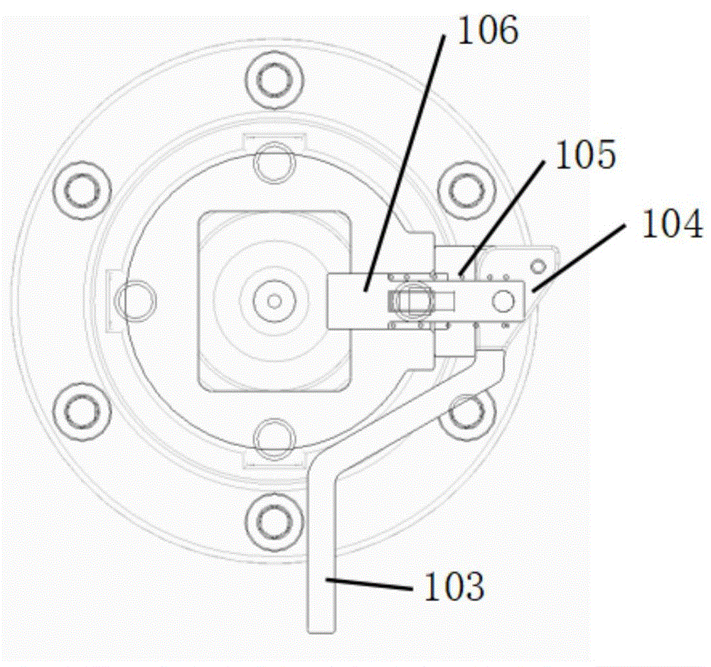
FIG. 1 is a plan view of a locked state of a locking switch assembly;
FIG. 2 is a plan view of the unlocked state of the lock switch assembly;
FIG. 3 is a plan view of the interface device with the robotic arm docked with the end effector;
FIG. 4 is a structural view of the second mating portion;
fig. 5 is an external structural view of the robot arm end effector quick interface device.
Detailed Description
In order that the manner in which the invention is worked will become more apparent, the invention will be further described with reference to the following description and specific examples taken in conjunction with the accompanying drawings in which:
as shown in fig. 1 to 5, a quick interface device for an end effector of a mechanical arm comprises a first matching portion, a second matching portion and a third matching portion, wherein the first matching portion is installed on an end joint 01 of the mechanical arm, the second matching portion is installed on the end effector 02 of the mechanical arm, and the first matching portion and the second matching portion are detachably connected.
The first matching part comprises a telescopic sleeve 101, a limiting sheet 102 and a locking switch component; the second matching part comprises a base disc 201, an extension cylinder 202, a middle disc (203) and a connecting column 204 which are integrally connected; the third mating portion includes a tool storage rack 301, a locking rack 302, an unlocking rack 303, an unlocking return spring 304, and a toggle column 305.
The base disc 201 is fixedly connected to the end effector 02 by six bolts. The side of the connecting column 204 is provided with a positioning hole 205. The locking switch assembly comprises a locking shift lever 103, a locking end 104, a locking spring 105 and a positioning pin 106; the locking end 104 is fixedly connected with the locking deflector rod 103, the positioning pin 106 is connected with the locking end 104 through a revolute pair, one end of the locking spring 105 is fixedly connected with the positioning pin 106, and the other end of the locking spring is fixedly connected with the locking end 104, so that the locking end 104 is tightly attached to the outer surface of the telescopic sleeve 101; a cavity is formed in the telescopic sleeve 101, the width of the openings at the two sides is different, the limiting sheet 102 is fixedly connected to the wide side of the telescopic sleeve 101, and the shape and the size of the opening at the narrow side of the telescopic sleeve 101 are the same as the cross section of the connecting column 204; the upper wall of the narrow side of the telescopic sleeve 101 is provided with an opening, the distance from the opening to the end part of the narrow side of the telescopic sleeve 101 is equal to the distance from the positioning hole 205 to the middle disc 203, and the positioning pin 106 and the opening form a sliding pair;
the locking frame 302 is fixedly connected with the tool storage frame 301, one end of the unlocking reset spring 304 is connected with the tool storage frame 301, the other end is connected with the unlocking frame 303, the toggle column 305 is fixedly connected with the locking frame 302,
the anticlockwise rotation of the telescopic sleeve 101 enables the toggle column 305 to be in contact with the locking toggle rod 103, the locking toggle rod 103 drives the locking end 104 to rotate under the action of the toggle column 305, and the positioning pin is inserted into the positioning hole of the connecting column 204 under the action of the revolute pair and the locking spring 105, so that the telescopic sleeve 101 and the end effector are locked.
Wherein, the end of the positioning pin 106 is a bevel.
A toggle column 306 is also fixedly connected to the unlocking frame 303.
The inner wall of the narrow side of the telescopic sleeve 101 is provided with a smooth inclined plane.
The connecting column 204 is shaped as a rectangular parallelepiped.
The cross-section of the connecting column 204 is a rounded rectangle.
The connecting column 204 is hollow.
The positioning holes 205 are formed on the long side surfaces of the connecting posts 204.
There are two positioning holes 205, and the arrangement is symmetrical.
When the unlocking and locking operations are not performed, the locking frame 302 comes into contact with the unlocking frame 303.
The quick interface device is used for locking and loosening the mechanical arm and the end effector and needs to be connected with a first matching part, a second matching part and an external third matching part on the mechanical arm in a matched mode.
The process of the mechanical arm picking up the end effector is divided into the following steps: first, the mechanical arm is aligned with the connecting column 204 of the second mating portion; secondly, the mechanical arm descends, the connecting column 204 is in contact with the telescopic sleeve 101 of the first matching part and gradually enters the cavity in the telescopic sleeve 101 until the middle disc 203 of the second matching part is clamped by the narrow side of the telescopic sleeve 101, and at the moment, because the distance from the opening on the telescopic sleeve 101 to the narrow side opening is equal to the distance from the positioning hole 205 to the middle disc 203, the opening on the telescopic sleeve 101 is exactly aligned with the positioning hole 205; thirdly, the mechanical arm rotates anticlockwise to enable the toggle column 305 to be in contact with the locking toggle rod 103, the locking toggle rod 103 is driven by the acting force of the toggle column 305 to drive the locking end head 104 to rotate, and the positioning pin 106 is inserted into the positioning hole 205 of the connecting column 204 under the action of the revolute pair and the locking spring 105, so that the mechanical arm and the end effector are locked successfully; fourthly, the mechanical arm drives the end effector to move towards the unlocking frame 303, the unlocking frame 303 and the unlocking return spring 304 are pushed, so that the gap between the locking frame 302 and the unlocking frame 303 is enlarged, and the end effector is taken out along the direction of the plane wall of the unlocking frame 303.
The process of the mechanical arm releasing the end effector is divided into the following steps: firstly, the mechanical arm drives the end effector to enable the extension cylinder 202 to be tightly attached to the plane wall of the unlocking frame 303 and move towards the unlocking frame 303, so that the gap between the locking frame 302 and the unlocking frame 303 is enlarged, the movement is stopped at the arc wall, and the extension cylinder is clamped between the locking frame 302 and the unlocking frame 303 again under the action of the unlocking return spring 304; secondly, the mechanical arm rotates clockwise, so that the toggle column 305 is in contact with the locking toggle rod 103, the locking toggle rod 103 is driven by the acting force of the toggle column 305 to drive the locking end 104 to rotate, and the positioning pin 106 is disengaged from the positioning hole 205 of the connecting column 204 under the action of the revolute pair and the locking spring 105; thirdly, the mechanical arm rises, the connecting column 204 is gradually separated from the telescopic sleeve 101 of the first matching part, and the release of the mechanical arm and the end effector is completed.
Those skilled in the art will appreciate that the details not described in the present specification are well known.
It should be understood that although the present description has been described in terms of various embodiments, not every embodiment includes only a single embodiment, and such description is for clarity purposes only, and those skilled in the art will recognize that the embodiments described herein may be combined as suitable to form other embodiments, as will be appreciated by those skilled in the art.
The above description is only illustrative of the present invention and is not intended to limit the scope of the present invention. Any equivalent alterations, modifications and combinations that may be made by those skilled in the art without departing from the spirit and principles of this application shall fall within the scope of this application.

Claims (10)

1.一种机械臂末端执行器快速接口装置,包括第一配合部、第二配合部和第三配合部,所述第一配合部安装在机械臂末端关节(01)上,所述第二配合部安装在机械臂末端执行器(02)上,所述第一配合部和所述第二配合部可拆卸连接;1. A quick interface device for an end effector of a manipulator, comprising a first fitting part, a second fitting part and a third fitting part, the first fitting part is mounted on the end joint (01) of the manipulator, the second fitting part is The matching part is installed on the end effector of the robotic arm (02), and the first matching part and the second matching part are detachably connected; 所述第一配合部包括伸缩套(101)、限位片(102)、锁定开关组件;所述第二配合部包括一体地连接的底座圆盘(201)、延长圆柱体(202)、中间圆盘(203)、连接柱(204);所述第三配合部包括工具存放架(301)、锁定架(302)、解锁架(303)、解锁复位弹簧(304)和拨动柱(305);The first matching part includes a telescopic sleeve (101), a limit piece (102), and a locking switch assembly; the second matching part includes a base disc (201), an elongated cylinder (202), a middle a disc (203), a connecting column (204); the third matching part includes a tool storage rack (301), a locking rack (302), an unlocking rack (303), an unlocking return spring (304) and a toggle column (305) ); 所述底座圆盘(201)通过六个螺栓与末端执行器(02)固定连接;所述连接柱(204)的侧面设有定位孔(205);The base disc (201) is fixedly connected to the end effector (02) through six bolts; a positioning hole (205) is provided on the side of the connecting column (204); 所述锁定开关组件包括锁定拨杆(103)、锁定端头(104)、锁定弹簧(105)和定位销(106);所述锁定端头(104)与所述锁定拨杆(103)固定连接,所述定位销(106)与所述锁定端头(104)通过转动副连接,所述锁定弹簧(105)一端与所述定位销(106)固定连接,另一端与所述锁定端头(104)固定连接,使所述锁定端头(104)紧贴所述伸缩套(101)外表面;所述伸缩套(101)内部有空腔,两侧开口宽窄不同,所述限位片(102)固定连接在所属伸缩套(101)的宽侧,所述伸缩套(101)窄侧开口的形状、大小与所述连接柱(204)的横截面相同;所述伸缩套(101)的窄侧的上壁有开口,开口到所述伸缩套(101)的窄侧的端部的距离与所述定位孔(205)到所述中间圆盘(203)的距离相等,所述定位销(106)与开口组成滑动副;The locking switch assembly includes a locking lever (103), a locking end (104), a locking spring (105) and a positioning pin (106); the locking end (104) is fixed to the locking lever (103) connection, the positioning pin (106) is connected with the locking end (104) through a rotating pair, one end of the locking spring (105) is fixedly connected with the positioning pin (106), and the other end is connected with the locking end (104) Fixed connection, so that the locking end head (104) is in close contact with the outer surface of the telescopic sleeve (101); the telescopic sleeve (101) has a cavity inside, and the openings on both sides have different widths. (102) is fixedly connected to the wide side of the corresponding telescopic sleeve (101), the shape and size of the narrow side opening of the telescopic sleeve (101) are the same as the cross section of the connecting column (204); the telescopic sleeve (101) There is an opening on the upper wall of the narrow side of the telescopic sleeve (101), and the distance from the opening to the end of the narrow side of the telescopic sleeve (101) is equal to the distance from the positioning hole (205) to the middle disc (203). The pin (106) and the opening form a sliding pair; 所述锁定架(302)与所述工具存放架(301)固定连接,所述解锁复位弹簧(304)一端连接所述工具存放架(301),一端连接所述解锁架(303),所述拨动柱(305)固定连接在所述锁定架(302)上,The locking rack (302) is fixedly connected with the tool storage rack (301), one end of the unlocking return spring (304) is connected with the tool storage rack (301), and one end is connected with the unlocking rack (303). The toggle column (305) is fixedly connected to the locking frame (302), 所述伸缩套(101)的逆时针旋转致使所述拨动柱(305)与所述锁定拨杆(103)接触,所述锁定拨杆(103)在所述拨动柱(305)的作用力下带动所述锁定端头(104)转动,所述定位销在转动副和所述锁定弹簧(105)的作用下插入所述连接柱(204)的定位孔(205),使所述伸缩套(101)和末端执行器锁紧。The counterclockwise rotation of the telescopic sleeve (101) causes the toggle post (305) to contact the locking lever (103), and the locking lever (103) acts on the toggle post (305). The locking end (104) is driven to rotate under the force, and the positioning pin is inserted into the positioning hole (205) of the connecting column (204) under the action of the rotating pair and the locking spring (105), so that the telescopic The sleeve (101) and the end effector are locked. 2.如权利要求1所述的机械臂末端执行器快速接口装置,其特征在于,所述定位销(106)的端部为斜面。2 . The quick interface device for the end effector of a robotic arm according to claim 1 , wherein the end of the positioning pin ( 106 ) is an inclined surface. 3 . 3.如权利要求1所述的机械臂末端执行器快速接口装置,其特征在于,所述解锁架(303)上也固定连接有一个拨动柱(306)。3 . The quick interface device for the end effector of a robotic arm according to claim 1 , wherein a toggle column ( 306 ) is also fixedly connected to the unlocking frame ( 303 ). 4 . 4.如权利要求1所述的机械臂末端执行器快速接口装置,其特征在于,所述伸缩套(101)的窄侧内壁设有光滑斜面。4 . The quick interface device for the end effector of a robotic arm according to claim 1 , wherein the inner wall of the narrow side of the telescopic sleeve ( 101 ) is provided with a smooth slope. 5 . 5.如权利要求1所述的机械臂末端执行器快速接口装置,其特征在于,所述连接柱(204)的形状为长方体。5 . The quick interface device for the end effector of a robotic arm according to claim 1 , wherein the connecting column ( 204 ) is in the shape of a rectangular parallelepiped. 6 . 6.如权利要求1所述的机械臂末端执行器快速接口装置,其特征在于,所述连接柱(204)的横截面是圆角矩形。6. The quick interface device for the end effector of a robotic arm according to claim 1, wherein the cross section of the connecting column (204) is a rectangle with rounded corners. 7.如权利要求1所述的机械臂末端执行器快速接口装置,其特征在于,所述连接柱(204)采用空心结构。7 . The quick interface device for the end effector of a robotic arm according to claim 1 , wherein the connecting column ( 204 ) adopts a hollow structure. 8 . 8.如权利要求5-7之一所述的机械臂末端执行器快速接口装置,其特征在于,所述定位孔(205)设在所述连接柱(204)的长边侧面上。8 . The quick interface device for a robotic arm end effector according to claim 5 , wherein the positioning hole ( 205 ) is provided on the long side of the connecting column ( 204 ). 9 . 9.如权利要求8所述的机械臂末端执行器快速接口装置,其特征在于,所述定位孔(205)有两个,且对称设置。9 . The quick interface device for the end effector of a robotic arm according to claim 8 , wherein there are two positioning holes ( 205 ), which are arranged symmetrically. 10 . 10.如权利要求1所述的机械臂末端执行器快速接口装置,其特征在于,未进行解锁和锁紧操作时,所述锁定架(302)与所述解锁架(303)接触。10. The quick interface device for the end effector of a robotic arm according to claim 1, characterized in that, when the unlocking and locking operations are not performed, the locking bracket (302) is in contact with the unlocking bracket (303).
CN202111160224.5A 2021-09-30 2021-09-30 A quick interface device for a mechanical arm end effector Active CN113733161B (en)

Priority Applications (1)

Application Number Priority Date Filing Date Title
CN202111160224.5A CN113733161B (en) 2021-09-30 2021-09-30 A quick interface device for a mechanical arm end effector

Applications Claiming Priority (1)

Application Number Priority Date Filing Date Title
CN202111160224.5A CN113733161B (en) 2021-09-30 2021-09-30 A quick interface device for a mechanical arm end effector

Publications (2)

Publication Number Publication Date
CN113733161A true CN113733161A (en) 2021-12-03
CN113733161B CN113733161B (en) 2023-01-17

Family

ID=78725791

Family Applications (1)

Application Number Title Priority Date Filing Date
CN202111160224.5A Active CN113733161B (en) 2021-09-30 2021-09-30 A quick interface device for a mechanical arm end effector

Country Status (1)

Country Link
CN (1) CN113733161B (en)

Cited By (1)

* Cited by examiner, † Cited by third party
Publication number Priority date Publication date Assignee Title
CN116636931A (en) * 2023-04-10 2023-08-25 上海微创医疗机器人(集团)股份有限公司 The end structure of the mechanical arm of the surgical robot

Citations (6)

* Cited by examiner, † Cited by third party
Publication number Priority date Publication date Assignee Title
US4993139A (en) * 1990-04-02 1991-02-19 The United States Of America As Represented By The United States Department Of Energy System for exchanging tools and end effectors on a robot
DE102014107655A1 (en) * 2014-05-30 2015-12-03 Voss Automotive Gmbh "Connector for fluid lines with internal adapter sleeve"
CN207195911U (en) * 2017-08-15 2018-04-06 上海未蓝工业技术有限公司 A kind of Cam lock quick famale connector of pluggable auto lock
CN109442121A (en) * 2018-12-26 2019-03-08 重庆维斯顿实业有限公司 A kind of adjustable hydraulic fitting of fast and easy connection
CN112298611A (en) * 2020-09-30 2021-02-02 北京空间飞行器总体设计部 Handheld docking mechanism suitable for space out-of-cabin activity
CN112524373A (en) * 2020-12-02 2021-03-19 江苏如一石化装备有限公司 Locking device of quick connector

Patent Citations (6)

* Cited by examiner, † Cited by third party
Publication number Priority date Publication date Assignee Title
US4993139A (en) * 1990-04-02 1991-02-19 The United States Of America As Represented By The United States Department Of Energy System for exchanging tools and end effectors on a robot
DE102014107655A1 (en) * 2014-05-30 2015-12-03 Voss Automotive Gmbh "Connector for fluid lines with internal adapter sleeve"
CN207195911U (en) * 2017-08-15 2018-04-06 上海未蓝工业技术有限公司 A kind of Cam lock quick famale connector of pluggable auto lock
CN109442121A (en) * 2018-12-26 2019-03-08 重庆维斯顿实业有限公司 A kind of adjustable hydraulic fitting of fast and easy connection
CN112298611A (en) * 2020-09-30 2021-02-02 北京空间飞行器总体设计部 Handheld docking mechanism suitable for space out-of-cabin activity
CN112524373A (en) * 2020-12-02 2021-03-19 江苏如一石化装备有限公司 Locking device of quick connector

Cited By (2)

* Cited by examiner, † Cited by third party
Publication number Priority date Publication date Assignee Title
CN116636931A (en) * 2023-04-10 2023-08-25 上海微创医疗机器人(集团)股份有限公司 The end structure of the mechanical arm of the surgical robot
CN116636931B (en) * 2023-04-10 2026-03-17 上海微创医疗机器人(集团)股份有限公司 Surgical robot end effector

Also Published As

Publication number Publication date
CN113733161B (en) 2023-01-17

Similar Documents

Publication Publication Date Title
CN108500964B (en) End effector assembly and robotic system having the same
CN210709624U (en) Clamping device
CN110978060B (en) Robot end tool quick changeover device and changeover method
CN108381597B (en) Passive manipulator
JP2001208157A (en) 6 DOF parallel mechanism for precision work
CN112959348A (en) Electrically-driven steel ball locking type robot terminal quick-change device
CN112497258B (en) Mechanical arm and joint quick-change interface thereof
EP1764291A2 (en) Automotive vehicle framing system
WO2022105806A1 (en) Joint quick-change connector of mechanical arm and mechanical arm
Berenstein et al. An open-access passive modular tool changing system for mobile manipulation robots
CN101913435A (en) A docking device for a space robot
CN114083560B (en) Quick joint changing device for tail end of robot arm and application method thereof
US4993139A (en) System for exchanging tools and end effectors on a robot
CN115072011A (en) Multi-arm spacecraft topology-variable mechatronic docking device and docking method
CN113370179A (en) Linear electromagnetic control claw type robot tail end quick-changing device
CN108177158B (en) A quick-change interface for a reconfigurable robotic arm based on memory alloys
Palpacelli et al. A lockable spherical joint for robotic applications
CN211541263U (en) Robot end effector quick changer
US5219318A (en) Spline screw autochanger
CN113733161B (en) A quick interface device for a mechanical arm end effector
JPH0343174A (en) Automatic tool exchange device
US8287016B2 (en) Gripper for robot
JP7836316B2 (en) End pickup devices, manipulators, and robots
CN117485601A (en) A two-stage floating docking type on-orbit replaceable mechanism and its pallet device
CN114986548B (en) Electromechanical quick-change interface for renewable robot for large-scale spatial operation

Legal Events

Date Code Title Description
PB01 Publication
PB01 Publication
SE01 Entry into force of request for substantive examination
GR01 Patent grant
GR01 Patent grant