Disclosure of Invention
Accordingly, there is a need to provide a mobile terminal protection case to solve the above technical problems.
The mobile terminal protection shell comprises a main body and an inner frame, wherein the main body comprises a side frame and a cover body, the side frame surrounds the outer edge of the cover body, and the side frame and the cover body jointly surround to form an accommodating cavity for accommodating a mobile terminal; the corner of the side frame is provided with a through hole communicated with the accommodating cavity; interior frame is inlayed in one side that the side frame is close to the holding chamber, and one side that the bight of interior frame deviates from the holding chamber passes through the through-hole protrusion in the surface of side frame, the side frame adopts first material to make, interior frame adopts the second material to make, the elasticity of first material is less than the elasticity of second material.
In one embodiment, the side frame comprises a first side part and a first corner part which are sequentially connected, and the first corner part of the side frame is provided with a first through hole communicated with the accommodating cavity; interior limit frame includes second side limit portion and second bight, one side that the second bight deviates from the holding chamber is passed through first through-hole protrusion in the surface of side frame.
In one embodiment, a side of the second corner portion facing away from the accommodating cavity is provided with a first groove.
In one embodiment, the first side edge of the side frame is provided with a second through hole communicated with the accommodating cavity, and one side of the second side edge of the inner frame, which is deviated from the accommodating cavity, protrudes out of the outer surface of the side frame through the second through hole.
In one embodiment, a side of the second side edge portion facing away from the accommodating cavity is provided with the first groove.
In one embodiment, the first and second through holes are spaced apart from each other; or the first through hole is communicated with the second through hole.
In one embodiment, one side of the first corner part of the inner frame, which is close to the accommodating cavity, is recessed towards a direction away from the accommodating cavity to form a second groove, and the second groove is used for forming a buffer air bag with an outer shell of the mobile terminal.
In one embodiment, a third groove is formed in one side, close to the accommodating cavity, of the first side edge portion of the inner frame, and the third groove is used for forming a buffering air bag with an outer shell of the mobile terminal.
In one embodiment, the inner frames are embedded at intervals on one side of the side frame close to the accommodating cavity, and functional areas are arranged between different inner frames on the side frame and are used for arranging functional holes or functional keys.
In one embodiment, the cover body includes a rear cover, and a side of the accommodating cavity opposite to the rear cover is open to facilitate the mobile terminal to be placed in.
In one embodiment, the protective case of the mobile terminal further comprises a metal bezel; the main body sequentially comprises a frame portion, a transition portion and a bottom portion in the thickness direction of the protective shell, the frame portion and the transition portion surround the outer edge of the bottom portion, the transition portion is located between the frame portion and the bottom portion, and the frame portion, the bottom portion and the transition portion are surrounded together to form an accommodating cavity for accommodating the mobile terminal; the main body is provided with a fourth groove along the circumferential direction of the protective shell, and the fourth groove is arranged on one side of the main body, which is far away from the accommodating cavity; the metal frame is inlayed in the fourth recess, the metal frame includes platform portion and rake in the thickness direction of protective housing, platform portion is located the bottom, at least part the rake is located transition portion, the contained angle between the reverse extension line of rake and platform portion is alpha, and 0 is < alpha < 90.
In one embodiment, the cover body comprises a front cover and a rear cover which are oppositely arranged, the side frame is enclosed between the front cover and the rear cover, and the main body is provided with a closable opening so as to facilitate the mobile terminal to be put in.
In one embodiment, the main body comprises a first sub-body and a second sub-body which are detachably connected, and the closable opening is formed between the first sub-body and the second sub-body; interior frame includes first frame, second frame and third frame, first frame is inlayed in one side that first components of a whole that can function independently is close to the holding chamber, second frame and third frame are all inlayed in one side that second components of a whole that can function independently is close to the holding chamber, the functional zone has been seted up between second frame and the third frame, the functional zone is used for setting up function hole or function button
The mobile terminal protection shell has the beneficial effects that:
according to the mobile terminal protection shell, the structure and the material of the main body and the inner frame and the connection relation between the main body and the inner frame are reasonably arranged, so that the protection shell is hard outside and soft inside, the side frame with smaller external elasticity can prevent the protection shell from excessively deforming when falling or being impacted by external force, the mobile terminal is further prevented from being separated from the protection shell, the inner softer inner frame inside can play a good buffering role, and one side of the inner softer inner frame, which is deviated from the containing cavity, protrudes out of the outer surface of the corner area of the side frame, so that the impact resistance of the protection shell can be improved, the impact force generated when the mobile terminal falls can be effectively dispersed and absorbed, and the mobile terminal can be prevented from being broken and damaged.
Detailed Description
In order to make the aforementioned objects, features and advantages of the present invention comprehensible, embodiments accompanied with figures are described in detail below. In the following description, numerous specific details are set forth in order to provide a thorough understanding of the present invention. This invention may, however, be embodied in many different forms and should not be construed as limited to the embodiments set forth herein.
In the description of the present invention, it is to be understood that the terms "central," "longitudinal," "lateral," "length," "width," "thickness," "upper," "lower," "front," "rear," "left," "right," "vertical," "horizontal," "top," "bottom," "inner," "outer," "clockwise," "counterclockwise," "axial," "radial," "circumferential," and the like are used in the orientations and positional relationships indicated in the drawings for convenience in describing the invention and to simplify the description, and are not intended to indicate or imply that the referenced device or element must have a particular orientation, be constructed and operated in a particular orientation, and are not to be considered limiting of the invention.
Furthermore, the terms "first", "second" and "first" are used for descriptive purposes only and are not to be construed as indicating or implying relative importance or implicitly indicating the number of technical features indicated. Thus, a feature defined as "first" or "second" may explicitly or implicitly include at least one such feature. In the description of the present invention, "a plurality" means at least two, e.g., two, three, etc., unless specifically limited otherwise.
In the present invention, unless otherwise expressly stated or limited, the terms "mounted," "connected," "secured," and the like are to be construed broadly and can, for example, be fixedly connected, detachably connected, or integrally formed; can be mechanically or electrically connected; they may be directly connected or indirectly connected through intervening media, or they may be connected internally or in any other suitable relationship, unless expressly stated otherwise. The specific meanings of the above terms in the present invention can be understood by those skilled in the art according to specific situations.
In the present invention, unless otherwise expressly stated or limited, the first feature "on" or "under" the second feature may be directly contacting the first and second features or indirectly contacting the first and second features through an intermediate. Also, a first feature "on," "over," and "above" a second feature may be directly or diagonally above the second feature, or may simply indicate that the first feature is at a higher level than the second feature. A first feature being "under," "below," and "beneath" a second feature may be directly under or obliquely under the first feature, or may simply mean that the first feature is at a lesser elevation than the second feature.
It will be understood that when an element is referred to as being "secured to" or "disposed on" another element, it can be directly on the other element or intervening elements may also be present. When an element is referred to as being "connected" to another element, it can be directly connected to the other element or intervening elements may also be present. The terms "vertical," "horizontal," "upper," "lower," "left," "right," and the like as used herein are for illustrative purposes only and do not denote a unique embodiment. In addition, it should be noted that, in the sectional views in the drawings herein, the section lines are provided for more clearly illustrating the specific structure of the embodiments of the present invention, and in one sectional view, the same section lines schematically represent the same component or represent different components made of the same material, and the shapes of the section lines, including the inclination angle and the spacing distance, do not strictly follow the section line setting of different materials in the mechanical drawing. For example, in the drawings herein, the hatching inclined at 45 ° does not necessarily represent a metal material, but may represent other non-metal materials.
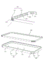
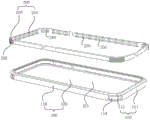
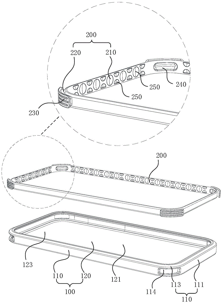
In one embodiment, as shown in fig. 1 and fig. 2, the mobile terminal protection case includes a main body 100 and an inner frame 200, where fig. 1 is a schematic structural diagram before the main body 100 and the inner frame 200 are connected, fig. 2 is a schematic structural diagram after the main body 100 and the inner frame 200 are connected, the main body 100 includes a side frame 110 and a cover 120, the side frame 110 surrounds an outer edge of the cover 120, and the side frame 110 and the cover 120 together surround to form an accommodating cavity 123 for accommodating the mobile terminal. Specifically, as shown in fig. 1 and 2, the cover body 120 includes a rear cover 121, and a side of the receiving cavity 123 opposite to the rear cover 121 is open to facilitate the mobile terminal to be placed therein. As shown in fig. 1 and 2, the side frame 110 and the inner frame 200 are rectangular, the side frame 110 includes a first side portion 111 and a first corner portion 113 connected in sequence, and the first corner portion 113 of the side frame 110 is provided with a first through hole 114 communicated with the accommodating cavity 123; the inner frame 200 includes a second side portion 210 and a second corner portion 220, the second side portion 210 is embedded in a side of the first side portion 111 close to the receiving cavity 123, and a side of the second corner portion 220 departing from the receiving cavity 123 protrudes out of an outer surface of the side frame 110 through the first through hole 114. The side frame 110 is made of a first material, and the inner frame 200 is made of a second material, wherein the elasticity of the first material is less than that of the second material, i.e., the second material is softer than the first material. In one embodiment, the first material may be a thermoplastic polyurethane, an elastomer rubber, or the like, and the second material may be a polycarbonate, a polyurethane, an elastomer rubber, or the like.
Thus, in the embodiment shown in fig. 1, the protective shell has a hard outer structure and a soft inner structure, the side frame 110 with low external elasticity can prevent the protective shell from excessively deforming when falling or being impacted by external force, and further prevent the mobile terminal from breaking away from the protective shell, the inner soft inner frame 200 can play a good buffering role, and the inner soft inner frame 200 protrudes out of the outer surface of the corner region of the side frame 110, so that the impact resistance of the protective shell can be improved, the impact force generated when the mobile terminal falls can be effectively dispersed and absorbed, and the mobile terminal can be prevented from being broken.
In addition, as shown in fig. 1, 2 and 8, where fig. 8 is a longitudinal sectional view of a corner of the protective shell, a first groove 230 is disposed on a side of the second corner 220 of the inner frame 200 away from the receiving cavity 123, the first groove 230 is transversely distributed in a stripe shape on a side of the second corner 220 of the inner frame 200 away from the receiving cavity 123, and the second corner 220 protrudes out of the outer surface of the side frame 110 through the first through hole 114, so that the first groove 230 protrudes out of the outer surface of the side frame 110 as shown in fig. 2 and 8. When the mobile terminal falls from a high place and the corner portion lands on the ground, the first groove 230 and the second corner portion 220 of the inner frame 200 protruding out of the outer surface of the side frame 110 can play a good role in buffering, so that the impact force generated when the mobile terminal falls can be effectively dispersed and absorbed, and the mobile terminal can be prevented from being broken and damaged.
It should be noted that, in the embodiment shown in fig. 1 and fig. 2, only the corner of the side frame 110 is provided with a through hole communicated with the accommodating cavity 123, and one side of the corner of the inner frame 200 departing from the accommodating cavity 123 protrudes out of the outer surface of the side frame 110 through the through hole. It is understood that, in other embodiments, the first side portion 111 of the side frame 110 is opened with a second through hole communicating with the receiving cavity 123, and a side of the second side portion 210 of the inner frame 200 departing from the receiving cavity 123 protrudes out of the outer surface of the side frame 110 through the second through hole. The first through hole 114 and the second through hole are spaced from each other; alternatively, the first through-hole 114 communicates with the second through-hole. In addition, a first groove 230 may be further disposed on a side of the second corner portion 220 away from the receiving cavity 123, that is, the first groove 230 is transversely distributed in a stripe shape on the second corner portion 220 and a side of the second side portion 210 of the inner frame 200 away from the receiving cavity 123. When the mobile terminal falls from a high place, the first groove 230, the second corner 220 and the second side 210 protruding from the outer surface of the side frame 110 can play a good role in buffering, so that the impact force generated when the mobile terminal falls can be effectively dispersed and absorbed, and the mobile terminal can be prevented from being broken.
In addition, in the embodiment shown in fig. 1 and fig. 2, the side frame 110 and the inner frame 200 are both rectangular, and a side of the second corner 220 of the inner frame 200 departing from the receiving cavity 123 protrudes out of the outer surface of the side frame 110 through a through hole; alternatively, the second corner 220 and the second side 210 of the inner frame 200, which face away from the receiving cavity 123, protrude from the outer surface of the side frame 110 through the through hole. It can be understood that, in other embodiments, the side frame 110 and the inner frame 200 may also be both circular or elliptical, at this time, the whole sides of the side frame 110 and the inner frame 200 are both corners, that is, the whole sides of the side frame 110 are both provided with through holes, and the whole sides of the inner frame 200 are all protruded out of the outer surface of the side frame 110 through the through holes. When the mobile terminal falls from a high place, the whole side edge of the inner frame 200 protruding out of the outer surface of the side frame 110 can play a good buffering role, so that the impact force generated when the mobile terminal falls is effectively dispersed and absorbed, and the mobile terminal is prevented from being broken and damaged.
In one embodiment, as shown in fig. 1, 2 and 8, a side of the first corner 113 of the inner frame 200 close to the receiving cavity 123 is recessed towards a direction away from the receiving cavity 123 to form a second groove 240, and the second groove 240 is used for forming a buffer air bag with an outer shell of the mobile terminal. In addition, as shown in fig. 3, a third groove 250 is disposed on a side of the first side portion 111 of the inner frame 200 close to the receiving cavity 123, and the third groove 250 is used for forming a buffer air bag with an outer housing of the mobile terminal. Thus, in the embodiment shown in fig. 1 to 3, the corner of the protective case of the mobile terminal forms triple protection, the first triple protection is a first groove 230 protruding out of the outer surface of the side frame 110, the second triple protection is a second corner 220 protruding out of the outer surface of the side frame 110, and the third triple protection is a second groove 240; the side positions of the mobile terminal protective case also form triple protections, the first is the first side portion 111 of the side frame 110, the second is the second side portion 210 of the inner frame 200, and the third is the third groove 250. Thus, in the embodiments shown in fig. 1 to 3, the mobile terminal protective case can effectively disperse and absorb the impact force when the mobile terminal falls, and prevent the mobile terminal from being broken.
In addition, in the embodiment shown in fig. 1, the inner frame 200 is integrally embedded in a side of the side frame 110 close to the receiving cavity 123. It is understood that, in other embodiments, as shown in fig. 4, the inner frames 200 may also be embedded on the side frame 110 at intervals, a functional area is opened between different inner frames 200 on the side frame 110, the functional area is used for setting a functional hole or a functional key, the functional hole includes at least one of a charging hole, a sound hole, an earphone hole, and the like, and the functional key includes at least one of a switch key, a volume adjustment key, and the like.
In addition, in one embodiment, the inner frame 200 is embedded on a side of the side frame 110 close to the receiving cavity 123 through a dispensing process or an in-mold injection molding process. It should be noted that the in-mold injection here refers to insert injection or in-mold secondary injection, that is, the side frame 110 is first injection molded, then the side frame 110 is placed in the molding mold cavity of the inner frame 200, and then the high-temperature molten material of the inner frame 200 is injected, so that the inner frame 200 and the side frame 110 are combined at high temperature; alternatively, the inner frame 200 is first injection-molded, and then the inner frame 200 is placed in the molding cavity of the side frame 110, and then the high-temperature molten material of the side frame 110 is injected, so that the inner frame 200 and the side frame 110 are combined at a high temperature. Therefore, the inner frame 200 is embedded on one side of the side frame 110 close to the accommodating cavity 123 through the in-mold injection molding process, so that the mechanical strength of the joint of the inner frame 200 and the side frame 110 can be improved.
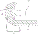
In addition, in one embodiment, as shown in fig. 5 and 6, the mobile terminal protection case further includes a metal bezel 300, the main body 100 sequentially includes a bezel portion 130, a transition portion 140 and a bottom portion 150 along a thickness direction of the protection case, the bezel portion 130 and the transition portion 140 surround an outer edge of the bottom portion 150, the transition portion 140 is located between the bezel portion 130 and the bottom portion 150, and the bezel portion 130, the bottom portion 150 and the transition portion 140 together enclose to form an accommodating cavity 123 for accommodating the mobile terminal; the main body 100 is provided with a fourth groove 115 along the circumferential direction of the protective shell, and the fourth groove 115 is arranged on one side of the main body 100 departing from the accommodating cavity 123; the metal frame 300 is embedded in the fourth groove 115, the metal frame 300 comprises a platform part 310 and an inclined part 320 along the thickness direction of the protective shell, the platform part 310 is positioned at the bottom part 150, at least part of the inclined part 320 is positioned at the transition part 140, and the included angle between the inclined part 320 and the reverse extension line of the platform part 310 is alpha, and alpha is more than 0 degrees and less than 90 degrees. The metal frame 300 is arranged, so that the bending resistance and impact resistance of the protective shell can be effectively improved, the impact force generated when the mobile terminal falls is effectively dispersed and absorbed, and the mobile terminal is prevented from being broken.
In the embodiment shown in fig. 3 and 6, the side frame 110 and the rear cover 121 are integrally formed of the same material. The side frame 110 and the rear cover 121 are not limited in material, and the side frame 110 and the rear cover 121 may be made of polyurethane, rubber elastomer, or other materials. It is understood that in other embodiments, as shown in fig. 7, the side frame 110 and the back cover 121 may be made of different materials. In a specific embodiment, the rear cover 121 can be made of PC plastic with better transparency and mechanical properties, the side frame 110 can be made of TPU soft rubber material to increase the impact resistance and the buffering capacity at the corners of the protective shell, and the inner frame 200 is made of TPE soft rubber material with better elasticity and softer properties. And the rear cover 121 is combined with the side frame 110 through an insert injection process to improve the mechanical strength of the combination of the two.
In another embodiment, as shown in fig. 9 to 11, the cover 120 includes a front cover 122 and a rear cover 121 disposed opposite to each other, the side frame 110 is enclosed between the front cover 122 and the rear cover 121, and the main body 100 is provided with a closable opening 430 to facilitate the mobile terminal to be inserted. The main body 100 includes a first division body 410 and a second division body 420 which are detachably connected, and a closable opening 430 is formed between the first division body 410 and the second division body 420; the inner frame 200 includes a first frame 270, a second frame 280 and a third frame 290, the first frame 270 is embedded in one side of the first split body 410 close to the accommodating cavity 123, the second frame 280 and the third frame 290 are both embedded in one side of the second split body 420 close to the accommodating cavity 123, a functional area 500 is disposed between the second frame 280 and the third frame 290, and the functional area 500 is used for setting a functional hole or a functional key. The function hole comprises at least one of a charging hole, a sound hole, an earphone hole and the like, and the function key comprises at least one of a switch key, a volume adjusting key and the like.
In addition, as shown in fig. 9 to 11, each of the first frame 270, the second frame 280, and the third frame 290 includes a second side portion 210 and a second corner portion 220, and accordingly, the side frame 110 includes a first side portion 111 and a first corner portion 113, the first corner portion 113 is provided with a first through hole 114 communicating with the accommodating cavity 123, the first side portion 111 is provided with a second through hole 112 communicating with the accommodating cavity 123, and the first through hole 114 is communicated with the second through hole 112. The side of the second corner 220 facing away from the receiving cavity 123 protrudes out of the outer surface of the side frame 110 through the first through hole 114, and the side of the second side edge 210 facing away from the receiving cavity 123 protrudes out of the outer surface of the side frame 110 through the second through hole 112. In addition, the first grooves 230 are respectively disposed on the second corner portion 220 and the second side portion 210 at the side departing from the accommodating cavity 123, and the first grooves 230 are transversely distributed in a stripe shape on the second corner portion 220 and the second side portion 210 at the side departing from the accommodating cavity 123 of the inner frame 200. When the mobile terminal falls from a high place, the first groove 230, the second corner 220 and the second side 210 protruding from the outer surface of the side frame 110 can play a good role in buffering, so that the impact force generated when the mobile terminal falls can be effectively dispersed and absorbed, and the mobile terminal can be prevented from being broken and damaged. In one embodiment, the mobile terminal 500 shown in fig. 9-11 is a bluetooth headset charging box, in which a headset receiving cavity (not shown) and a headset charging potential (not shown) are disposed.
In addition, as shown in fig. 11, a circular arc-shaped fifth groove 260 is formed in one side of the inner frame 200 close to the accommodating cavity 123, and the fifth groove 260 is used for forming a buffering airbag with the outer housing of the mobile terminal, so that the buffering airbag can further disperse and absorb the impact force generated when the mobile terminal falls, and the mobile terminal is prevented from being broken.
According to the mobile terminal protection shell, the connection relation between the main body 100 and the inner frame 200 and the connection relation between the main body and the inner frame are reasonably arranged, so that the protection shell is hard outside and soft inside, the side frame 110 with smaller external elasticity can prevent the protection shell from excessively deforming when falling or being impacted by external force, the mobile terminal is further prevented from being separated from the protection shell, the inner frame 200 with softer inside can play a good buffering role, and the side, deviating from the accommodating cavity 123, of the inner frame 200 with softer inside protrudes out of the outer surface of the corner area of the side frame 110, so that the impact resistance of the protection shell can be improved, the impact force generated when the mobile terminal falls can be effectively dispersed and absorbed, and the mobile terminal can be prevented from being broken.
The technical features of the embodiments described above may be arbitrarily combined, and for the sake of brevity, all possible combinations of the technical features in the embodiments described above are not described, but should be considered as being within the scope of the present specification as long as there is no contradiction between the combinations of the technical features.
The above-mentioned embodiments only express several embodiments of the present invention, and the description thereof is more specific and detailed, but not construed as limiting the scope of the invention. It should be noted that, for a person skilled in the art, several variations and modifications can be made without departing from the inventive concept, which falls within the scope of the present invention. Therefore, the protection scope of the present patent shall be subject to the appended claims.