CN113692334A - Robot system and method for manufacturing molded article - Google Patents
Robot system and method for manufacturing molded article Download PDFInfo
- Publication number
- CN113692334A CN113692334A CN202080028544.2A CN202080028544A CN113692334A CN 113692334 A CN113692334 A CN 113692334A CN 202080028544 A CN202080028544 A CN 202080028544A CN 113692334 A CN113692334 A CN 113692334A
- Authority
- CN
- China
- Prior art keywords
- burr
- molded body
- holding
- state
- molded
- Prior art date
- Legal status (The legal status is an assumption and is not a legal conclusion. Google has not performed a legal analysis and makes no representation as to the accuracy of the status listed.)
- Granted
Links
Images






Landscapes
- Moulds For Moulding Plastics Or The Like (AREA)
- Manipulator (AREA)
- Blow-Moulding Or Thermoforming Of Plastics Or The Like (AREA)
Abstract
Provided is a robot system capable of effectively removing burrs from a molded article. According to the present invention, there is provided a robot system including a robot arm to which the robot hand is attached, a robot hand, a holding mechanism provided in the robot hand and configured to hold a molded body, the molded body including a molded body main body and a burr provided around the molded body main body, and a dividing mechanism configured to divide the burr and the molded body main body in a state where the holding mechanism holds the molded body.
Description
Technical Field
The present invention relates to a robot system that can be used for removing burrs from a molded article, and a method for manufacturing a molded article using the robot system.
Background
In patent document 1, deburring is performed in a state where a robot arm is driven to take out a molded body from a mold, and the molded body is fixed to a holding device for deburring.
Documents of the prior art
Patent document
Patent document 1: japanese patent laid-open No. 2015-160422
Disclosure of Invention
(problems to be solved by the invention)
In the method of patent document 1, since the molded body taken out of the mold is temporarily fixed to a holding device for deburring, deburring is performed in this state, the number of work steps required for deburring increases.
The present invention has been made in view of such circumstances, and provides a robot system capable of effectively removing burrs from a molded article.
(means for solving the problems)
According to the present invention, there is provided a robot system including a robot arm to which the robot hand is attached, a robot hand, a holding mechanism provided in the robot hand and configured to hold a molded body, the molded body including a molded body main body and a burr provided around the molded body main body, and a dividing mechanism configured to divide the burr and the molded body main body in a state where the holding mechanism holds the molded body.
The invention is configured to divide the burr and the molded body in a state that the holding mechanism holds the molded body, so that the burr can be effectively removed.
Hereinafter, various embodiments of the present invention will be described by way of examples. The embodiments shown below can be combined with each other.
Preferably, in the robot system, the holding mechanism includes a main body holding mechanism that holds the molded body main body.
Preferably, in the robot system, the dividing means includes a burr removing means having an abutting body, and the body holding means is configured to divide the burr and the molded body by causing the burr to collide with the abutting body in a state where the molded body is held.
Preferably, in the robot system, the burr removing mechanism includes a pair of the abutting bodies, a size of an opening between the pair of abutting bodies is variable, and the size of the opening is set so that the burr collides with the abutting bodies in a state where the molded body can pass through the opening and the burr collides with the abutting bodies.
Preferably, in the robot system, the dividing means includes at least one projecting means including a projecting portion, and the robot system is configured to divide the burr and the molded body main body by moving the abutting body from the holding surface toward the facing surface in a state where the projecting portion abuts against the facing surface facing the holding surface where the molded body main body is held by the main body holding means.
Preferably, the robot system further includes an inclined member having an inclined surface disposed below the burr removing mechanism, and the burr divided by the burr removing mechanism is transported by sliding along the inclined surface.
In the robot system, it is preferable that the projecting mechanism is disposed below the inclined surface, and the projecting portion projects from the inclined surface through a through hole provided in the inclined surface.
Preferably, in the robot system, the burr includes a burr body and a thin portion, the thin portion has a smaller thickness than the burr body and is provided along an edge of the molded body, and the dividing means includes at least one projecting means, the projecting means includes a projecting portion, and the projecting portion is configured to cause a tip of the projecting portion to abut against the thin portion in a state where the holding means holds the molded body, and to divide the burr body and the molded body by damaging the thin portion with the tip.
Preferably, in the robot system, the dividing means includes a plurality of the projecting means, and the plurality of projecting means are arranged at intervals along an edge of the molded body main body.
Preferably, in the robot system described above, the holding mechanism includes a burr holding mechanism that holds the burr body.
Preferably, the robot system includes a1 st mold and a2 nd mold which are openable and closable, the 1 st mold and the 2 nd mold are configured to form the molded article by molding a parison, and the holding mechanism holds the molded article in a state where the molded article is held by the 1 st mold after the molded article is formed.
Preferably, in the robot system, the 1 st mold is more easily engaged with the molded body than the 2 nd mold.
Drawings
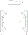
Fig. 1 is a vertical cross-sectional view showing a state in which a parison 3 is disposed between opened molds 1, 2 in embodiment 1 of the present invention.
Fig. 2 shows the state of fig. 1 after the molds 1, 2 are closed to form the parison 3.
In fig. 3, fig. 3A is an enlarged view of the area a in fig. 1, and fig. 3B is an enlarged view of the area a in fig. 2.
Fig. 4 shows the state after the molds 1 and 2 are opened from the state of fig. 2.
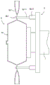
Fig. 5 shows a state after the molded body 4 is held by the holding mechanism 6a of the robot hand 6 from the state shown in fig. 4.
Fig. 6 shows the state after the molded body 4 is taken out from the molds 1 and 2 from the state of fig. 5.
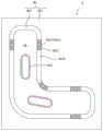
Fig. 7 is a diagram showing in detail the shape and arrangement of the main body holding means 6a1, the projecting means 6b1, and the molded body 4 in the cross section corresponding to the section a-a in fig. 6.
Fig. 8 shows a state after the thin portion 4b2 is damaged by touching the tip of the protruding portion 6b11 to the thin portion 4b2 from the state of fig. 6.
Fig. 9 is a diagram showing a state after the thin-walled portion 4b2 is damaged in the partial region 4b21 of the thin-walled portion 4b2, and corresponds to fig. 7.
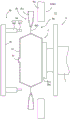
Fig. 10 shows a state immediately before the molded body main body 4a and the burr main body 4b1 are divided by the burr removing mechanism 8 from the state of fig. 8.
Fig. 11 shows a state after the molded body main body 4a and the burr main body 4b1 are divided by the burr removing mechanism 8 from the state of fig. 10.
Fig. 12 is a view corresponding to fig. 6 in embodiment 2 of the present invention.
Fig. 13 is a view corresponding to fig. 4 in embodiment 3 of the present invention.
Fig. 14 is a view corresponding to fig. 5 in embodiment 3 of the present invention.
Fig. 15 is a view corresponding to fig. 6 in embodiment 3 of the present invention.
Fig. 16 is a view corresponding to fig. 8 in embodiment 3 of the present invention.
Fig. 17 is a view corresponding to fig. 2 in embodiment 4 of the present invention.
Fig. 18 is a view corresponding to fig. 4 in embodiment 4 of the present invention.
Fig. 19 is a view corresponding to fig. 6 in embodiment 5 of the present invention.
Fig. 20 is a view corresponding to fig. 8 in embodiment 5 of the present invention.
Fig. 21 is a view corresponding to fig. 6 in embodiment 6 of the present invention.
Fig. 22 is a diagram showing a state immediately before the thin portion 4b2 is damaged in embodiment 6 of the present invention.
Fig. 23 is a view corresponding to fig. 8 in embodiment 6 of the present invention.
Fig. 24 is a view corresponding to fig. 8 in embodiment 7 of the present invention.
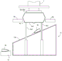
Fig. 25 is a diagram showing a state in which the molded body 4 is disposed between the burr removing mechanism 8 and the inclined member 13 in embodiment 8 of the present invention.
Fig. 26 is a view showing a state where the opening 8b is narrowed and the protrusion 9a1 is brought into contact with the facing surface 4a1 from the state shown in fig. 25.
Fig. 27 is a view showing a state where the contact body 8a is brought into collision with the burr 4b from the state of fig. 26, and the burr 4b is split from the molded body main body 4 a.
Detailed Description
Hereinafter, embodiments of the present invention will be described. Various feature items shown in the embodiments shown below may be combined with each other. Further, each feature independently establishes the invention.
1. Embodiment 1
A method for producing a molded article according to embodiment 1 of the present invention will be described with reference to fig. 1 to 11. Note that, the shapes and the arrangements of the main body holding mechanism 6a1, the protruding mechanism 6b1, and the molded body 4 are shown in detail in fig. 7 and 9, and the shapes and the arrangements of these structures are schematically shown in the other figures for convenience of illustration. Therefore, the shapes and the arrangements of the above-described structures in fig. 7 and 9 do not completely match those in the other drawings.
The method for producing a molded article according to the present embodiment includes: a molding step, a holding step, and a dividing step. The dividing step is preferably followed by a full-circle dividing step.
The manufacturing method may be implemented using the robot system 11 shown in fig. 4 and 10. The robot system 11 includes: a robot arm 7, a robot hand 6, a holding mechanism 6a, and a dividing mechanism 6 b. The holding mechanism 6a is provided in the robot hand 6. The dividing means 6b includes a protruding means 6b1 burr removing means 8. The projecting mechanism 6b1 is provided on the robot hand 6, and the burr removing mechanism 8 is separated from the robot hand 6.
1-1. Forming Process
As shown in fig. 1 to 4, in the molding step, a parison 3 is molded using an openable and closable first mold 1 and second molds 1 and 2 to form a molded body 4.
First, as shown in fig. 1, a parison 3 is formed by extruding a molten resin from a die gap provided in a die head 5, and is disposed between a1 st die and a2 nd die 1, 2. The molten resin can be formed by melt-kneading the raw material resins. The raw material resin is, for example, a thermoplastic resin such as polyolefin, and examples of the polyolefin include: low density polyethylene, linear low density polyethylene, high density polyethylene, polypropylene, ethylene-propylene copolymers, and mixtures thereof. The molten resin may or may not have added a blowing agent. When a foaming agent is added to the molten resin, the parison 3 is a foamed parison. The parison 3 may be cylindrical or sheet-like.
The molds 1, 2 each have a cavity 1a, 2a and a pressing portion 1b, 2b provided along the edge thereof. As shown in fig. 3A, the mold 1 is provided with an undercut structure portion 1 c. The undercut structure is a structure that forms an engagement structure between the molded body and the mold, and is, for example, an inverted cone shape. The undercut structure 1c may be provided in the cavity 1a or outside the pressing portion 1 b. The undercut structure portion 1c is preferably provided in a portion of the molded body 4a to be removed after molding (for example, a bag portion provided in an opening portion if the molded article is a pipe) or the burr body 4b 1. This is because the engaging portion 4c formed by the undercut structure portion 1c is not left in the final product (see fig. 6).
As shown in fig. 2, the molds 1 and 2 are closed with the parison 3 disposed between the molds 1 and 2, and the parison 3 in the cavities 1a and 2a is molded in this state, thereby obtaining a molded body 4. Examples of the method of molding the parison 3 include: blow molding, vacuum forming, and the like.
As shown in fig. 6, the molded body 4 includes a molded body main body 4a as a product (molded article) and a burr 4b provided around the molded body main body. The shape of the molded body 4a follows the inner surface shape of the cavities 1a, 2 a. The molded body 4a is preferably a hollow body. The hollow body may be filled with a filler such as a foam (e.g., a sandwich panel). The burr 4b includes a burr main body 4b1 and a thin- walled portion 4b 2. The wall thickness of the thin-walled portion 4b2 is smaller than that of the burr body 4b 1. The thin-walled portion 4b2 is provided along the edge of the molded body 4 a.
The thin portion 4b2 is formed by compressing the parison 3 with the pressing portions 1b, 2b so that the wall thickness thereof becomes extremely thin. The parison 3 has a burr body 4b1 at the outer side of the pinched portions 1b, 2 b.
As the pressure at the time of closing the dies 1 and 2 is increased, the thickness of the thin portion 4b2 is decreased, and the thin portion 4b2 is damaged by a dividing mechanism described later, so that the burr main body 4b1 and the molded body main body 4a are easily divided. The thickness of the thin portion 4b2 is, for example, 0.001 to 0.5mm, specifically, 0.001, 0.01, 0.05, 0.1, 0.2, 0.3, 0.4, 0.5mm, and may be in a range between any two values exemplified here.
After the parison 3 has been formed, the moulded body 4 can be removed by opening the moulds 1, 2, as shown in figure 4. Since the undercut structure portion 1c is provided in the cavity 1a, the molded body 4 is not easily separated from the mold 1 because the molded body main body 4a is engaged with the mold 1 as shown in fig. 3B. In contrast, since there is no undercut structure in the mold 2, the molded body 4 can be smoothly separated from the mold 2. Thus, the mold 1 is more easily engaged with the molded body 4 than the mold 2, and when the molds 1 and 2 are opened after molding, the molded body 4 moves together with the mold 1 in a state of being engaged with the mold 1 as shown in fig. 4.
1-2. robot hand 6
The holding step and the dividing step are performed by using the robot hand 6 shown in fig. 4. The robot hand 6 is mounted to a robot arm 7 in use. The robot arm 7 has a function of moving the robot hand 6. The robot arm 7 may have the number of axes necessary to perform various steps including the method of the present embodiment, and preferably has 6 or more axes.
The robot hand 6 includes a holding mechanism 6a and a projecting mechanism 6b1 on a base 6 c. The holding mechanism 6a is configured to hold the molded body 4. The protruding mechanism 6b1 is configured to be damaged at least at 1 point of the thin-walled portion 4b2 in a state where the molded body 4 is held by the holding mechanism 6a, thereby dividing the burr main body 4b1 and the molded body main body 4 a.
The holding mechanism 6a includes a body holding mechanism 6a1 that holds the molded body 4 a. The main body holding mechanism 6a1 of the present embodiment is an adsorbing sheet having a function of holding (adsorbing) the molded body main body 4a by an adsorbing force, but may be a member holding the molded body main body 4a by another configuration.
The protrusion mechanism 6b1 includes a protrusion 6b11 and an actuator 6b12 that drives the protrusion 6b 11. The actuator 6b12 is configured to change the position of the tip of the projection 6b 11. The protrusion 6b11 causes the tip of the protrusion 6b11 to touch the thin-walled portion 4b2 in response to the driving of the actuator 6b12, thereby damaging the thin-walled portion 4b2 and dividing the burr body 4b1 from the molded body 4 a. The thin portion 4b2 can be damaged by the tip of the protrusion 6b11 colliding strongly with the thin portion 4b2, or by the tip of the protrusion 6b11 being pressed strongly against the thin portion 4b 2. In addition, when the tip of the protrusion 6b11 is sharp, the thin-walled portion 4b2 can be damaged by tearing the thin-walled portion 4b2 with the tip of the protrusion 6b 11.
The projecting mechanism 6b1 is constituted by, for example, a cylinder mechanism. The cross-sectional shape of the tip of the protrusion 6b11 is not particularly limited, and may be circular or another shape. The front end of the protrusion 6b11 may be flat, curved, or pointed.
As shown in fig. 7, the molded body 4 of the present embodiment is configured such that a burr 4b is provided around a substantially L-shaped molded body main body 4 a. The body holding mechanism 6a1 is provided at a plurality of positions (2), and the protrusion mechanism 6b1 is also provided at a plurality of positions (5). A plurality of protruding means 6b1 are arranged spaced apart along the edge of the moulded body 4 a. Specifically, 2 projecting mechanisms 6b1 are disposed near one end of the L, 2 projecting mechanisms 6b1 are disposed near the other end of the L, and the remaining 1 projecting mechanism 6b1 is disposed inside the L corner. Either one is provided at a position where the tip of the protrusion 6b11 touches the thin wall portion 4b 2.
1-3. maintenance step
In the holding step, the holding mechanism 6a holds the molded body 4. Specifically, the robot hand 6 is moved between the molds 1 and 2 in the opened state as shown in fig. 4, and the main body holding mechanism 6a1 is brought into contact with the molded body main body 4a as shown in fig. 5 to suction-hold the molded body main body 4 a.
Next, in a state where the molded body 4 is held by the holding mechanism 6a, the molded body 4 is taken out from the molds 1, 2 by moving the robot hand 6 as shown in fig. 6. At this time, the engaging portion 4c formed by the undercut structure portion 1c is elastically deformed so as to be disengaged from the undercut structure portion 1 c. Since the burr body 4b1 is connected to the die 5 in the state of fig. 5, the burr body 4b1 is torn off from the die 5 or the burr body 4b1 is cut by a cutting mechanism not shown in the figure to be in the state shown in fig. 6.
1-4. dividing step
When the actuator 6b12 is driven from the state of fig. 6, the tip of the protrusion 6b11 touches the thin-walled portion 4b2, and the thin-walled portion 4b2 is damaged to split the burr main body 4b1 and the molded body main body 4a at least at 1 of the thin-walled portion 4b2 as shown in fig. 8. As shown in fig. 9, since the projecting mechanism 6b1 of the present embodiment is provided at 5, the thin portion 4b2 is damaged in the region 4b21 near the portion where the projecting portion 6b11 at 5 touches the thin portion 4b 2.
As shown in fig. 9, in the state after the dividing step, the molded body 4a in the partial region 4b22 of the thin-walled portion 4b2 is connected to the burr body 4b 1.
Here, the dividing step is followed by a full-circumference dividing step of dividing the molded body main body 4a and the burr main body 4b1 over the entire circumference of the molded body main body 4 a.
1-5. Whole-cycle dividing step
As shown in fig. 10, the entire-periphery dividing step divides the molded body main body 4a and the burr main body 4b1 around the entire periphery of the molded body main body 4a by using the burr removing mechanism 8.
The burr removing mechanism 8 is preferably provided with a pair of abutting bodies 8a as shown in fig. 10. An opening (gap) 8b is provided between the pair of abutting bodies 8 a. The pair of abutting bodies 8a is configured to change the size of the opening 8 b.
This step can be carried out by the following method. First, as shown in fig. 10, the opening 8b is enlarged in a state where the molded body 4 is positioned on the right side of the burr removing means 8 so that the entire molded body 4 can pass through the opening 8b, and the molded body 4 is moved so that the entire molded body 4 passes through the opening 8b, thereby bringing the molded body 4 into a state where it is positioned on the left side of the burr removing means 8. Thereafter, the reduced opening 8b is in a state where the molded body 4a can pass but the burr body 4b1 cannot pass as shown in fig. 10.
Next, the molded body 4 is relatively moved with respect to the burr removal mechanism 8, so that the burr main body 4b1 abuts against the abutting body 8a and the molded body main body 4a passes through the opening 8 b. In fig. 10, the molded body 4 is moved rightward with respect to the burr removing mechanism 8. As described above, the thin wall portion 4b2 of the entire circumference of the molded body main body 4a is damaged, and only the molded body main body 4a passes through the opening 8b, so that the molded body main body 4a and the burr main body 4b1 of the entire circumference of the molded body main body 4a are divided as shown in fig. 11. In the dividing step, since the partial region 4b21 of the thin portion 4b2 is damaged, the damaged portion becomes a starting point, and the residual region 4b22 of the thin portion 4b2 is easily damaged.
In this step, only the molded body 4 may be moved, only the burr removal mechanism 8 may be moved, or both may be moved.
1-6. post-processing
As shown in fig. 11, the remains 4b23 of the damaged thin-walled portion 4b2 are connected to the molded body 4a separated from the burr body 4b1 in the entire-periphery dividing step. The molded article can be obtained by appropriately removing the remains 4b23 with a cutter or the like, or by removing a portion unnecessary as a molded article (for example, a pocket portion formed in the opening in the case of a duct).
2. Embodiment 2
In embodiment 1, the tip of the protrusion 6b11 is touched to the thin wall portion 4b2 from the state of fig. 6, but in this method, the molded body main body 4a may be detached from the holding mechanism 6a by an impact at the time of touching the protrusion 6b 11.
In the dividing step of the present embodiment, the burr main body 4b1 and the molded body main body 4a are divided in a state where the facing surface 4a1 facing the holding surface 4a3 of the molded body 4 held by the holding mechanism 6a is in contact with the contact member 12 separated from the robot hand 6. That is, in this state, the protruding portion 6b11 is brought into contact with the thin portion 4b 2.
According to this method, the molded body main body 4a can be prevented from being detached from the holding mechanism 6a by the impact at the time of touching the protruding portion 6b 11.
3. Embodiment 3
The holding mechanism 6a of the present embodiment includes a burr holding mechanism 6a2 that holds the burr main body 4b 1. As an example, the burr holding mechanism 6a2 includes a clamp portion 6a21 for holding the burr main body 4b1, and an actuator 6a22 for driving the clamp portion 6a 21. The actuator 6a22 is configured to displace the clamp portion 6a21 or open and close the clamp portion 6a21 when the clamp portion 6a21 clamps the burr body 4b 1. 1 burr holding means 6a2 are provided at the upper side position of the molded body 4a and the lower side position of the molded body 4a, respectively.
The robot hand 6 includes a base 6 d. The base 6c and the base 6d are connected by an actuator 6e, and the distance between the two can be changed. The burr retaining mechanism 6a2 is provided on the base 6 d. The robot arm 7 is coupled to the base 6 d.
In the holding step of the present embodiment, the robot hand 6 is moved between the molds 1 and 2 in the open state as shown in fig. 13, and the molded body 4 is held by sandwiching the burr main body 4b1 with the burr holding mechanism 6a2 as shown in fig. 14. In this state, the molded body 4 can be taken out from the molds 1 and 2, and the body holding means 6a1 can be brought into contact with the molded body 4a to hold the molded body 4a by suction. Body holding mechanism 6a1 can hold molded body 4a before clamping burr body 4b1 with burr holding mechanism 6a 2.
Next, in a state where the molded body 4 is held by the holding mechanism 6a, the molded body 4 is taken out from the molds 1, 2 by the mobile robot hand 6 as shown in fig. 15. Before the molded body 4 is removed from the mold, the molded body 4a may be held by the body holding mechanism 6a1, and after the molded body 4 is removed from the mold, the burr body 4b1 may be sandwiched by the burr holding mechanism 6a 2.
Next, in the dividing step, as in embodiment 1, the actuator 6b12 is driven to bring the tip of the protrusion 6b11 into contact with the thin wall portion 4b2 as shown in fig. 16. As described above, the thin-walled portion 4b2 may be damaged at least 1 point of the thin-walled portion 4b2 as shown in fig. 16.
In the present embodiment, since the tip of the protrusion 6b11 is brought into contact with the thin-walled portion 4b2 in a state where the burr main body 4b1 is held by the burr holding mechanism 6a2, the force applied by the protrusion 6b11 is easily concentrated on the thin-walled portion 4b2, and the thin-walled portion 4b2 is easily damaged. When the tip of the protrusion 6b11 touches the thin wall portion 4b2, the clip portion 6a21 is preferably moved in the direction opposite to the protrusion 6b 11. As described above, the thin-walled portion 4b2 is easily damaged due to a strong force applied to the thin- walled portion 4b 2.
4. Embodiment 4
The upper and lower sides of the dies 1 and 2 of the present embodiment are provided with the burr holding mechanism 10, respectively, and the burr holding mechanism 10 has a function of holding the burr body 4b 1. The burr holding mechanism 10 may be attached to the robot hand 6, or may be a mechanism separate from the robot hand 6. The burr retaining means 10 may also be provided on one of the upper and lower sides of the moulds 1, 2.
In the present embodiment, as shown in fig. 17, the burr main body 4b1 is held by the burr holding mechanism 10 in a state where the molds 1, 2 are closed. As shown in fig. 18, when the molds 1, 2 are opened, the burr holding mechanism 10 is moved together with the mold 1. With this configuration, the molded body 4 can be moved together with the mold 1 without providing the undercut structure portion 1c to the mold 1.
Instead of moving the burr holding means 10 together with the mold 1, the molded body 4 may be positioned between the molds 1 and 2, and the molded body 4 in this state may be held by the holding means 6 a. When held by the holding mechanism 6a, the molded body 4 can be pressed against the mold 1. Further, the burr retaining means 10 may be configured to hold the molded body 4 and remove it from the molds 1 and 2. At this time, the holding mechanism 6a holds the molded body 4 after being taken out from the molds 1, 2.
5. Embodiment 5
In the present embodiment, as shown in fig. 19, the dividing mechanism 6b includes at least one protruding mechanism 9a, and the protruding mechanism 9a is provided on a base 9b separated from the robot hand 6. The protrusion mechanism 9a includes a protrusion 9a1 and an actuator 9a2 for driving the protrusion 9a1, and can damage the thin-walled portion 4b2 by the same operation as the protrusion mechanism 6b 1. For example, the protruding mechanism 9a is configured as shown in fig. 7, like the protruding mechanism 6b 1.
In the holding step of the present embodiment, as in embodiment 1, the molded body 4 is taken out from the molds 1 and 2 by moving the robot hand 6 in a state where the holding mechanism 6a holds the molded body 4 as shown in fig. 5. Thereafter, as shown in fig. 19, the molded body 4 is moved to a position where the tip of the protrusion 9a1 faces the thin portion 4b 2.
In the dividing step of the present embodiment, as shown in fig. 20, the actuator 9a2 is driven to bring the tip of the protrusion 9a1 into contact with the thin wall portion 4b 2. As described above, the thin wall portion 4b2 may be damaged at least 1 of the thin wall portion 4b2 as shown in fig. 20.
6. Embodiment 6
In embodiment 1, the molded body main body 4a and the burr main body 4b1 are separated by performing the entire-circumference dividing step after the dividing step damages a part of the thin portion 4b2, but in this embodiment, the molded body main body 4a and the burr main body 4b1 can be separated in one step.
In the present embodiment, the dividing mechanism 6b includes a projecting mechanism 9a and a burr removing mechanism 8 as shown in fig. 21.
This step can be carried out by the following method. First, the molded body 4 and the burr removal mechanism 8 are arranged as shown in fig. 21 by the same method as in embodiment 1.
Next, when the projection 9a1 and the abutting body 8a are relatively moved in the direction in which the projection 9a1 is directed into the opening 8b from the state of fig. 21, as shown in fig. 22, the tip of the projection 9a1 abuts against the thin portion 4b2, and the abutting body 8a abuts against the burr body 4b 1.
When the protrusion 9a1 and the contact body 8a are further moved relative to each other from the state shown in fig. 22, the thin portion 4b2 is damaged over the entire circumference of the molded body main body 4a as shown in fig. 23, and the molded body main body 4a and the burr main body 4b1 are separated. In one example, the thin wall portion 4b2 is damaged at the tip of the protrusion 9a1 first, and the damaged portion becomes a starting point, and other portions are damaged.
The relative movement of the protrusion 9a1 and the contact body 8a may move only the contact body 8a, only the protrusion 9a1, or both. As a method of moving the protrusion 9a1, the entire protrusion mechanism 9a may be moved, or only the protrusion 9a1 may be moved by driving the actuator 9a 2.
7. Embodiment 7
In the present embodiment, as shown in fig. 24, the tip of the projecting means 9a is in contact with the edge 4a2 of the molded body main body 4a or is arranged in close proximity thereto. At this time, when the molded body 4a and the burr body 4b1 are separated, most or the entire thin portion 4b2 is connected to the burr body 4b1, and the thin portion 4b2 hardly or not at all remains in the molded body 4 a. In this case, a post-process of removing the remains of the thin portion 4b2 from the molded body main body 4a can be omitted.
8. Embodiment 8
In the robot system 11 of the present embodiment, the dividing means 6b includes the projecting means 9a and the burr removing means 8. An inclined member 13 having an inclined surface 13a is disposed below the burr removing mechanism 8. The inclined surface 13a is provided with a through hole 13 b. The projection mechanism 9a is disposed below the inclined surface 13 a. The protrusion 9a1 can protrude from the inclined surface 13a through the through hole 13 b. Preferably, a plurality of projecting mechanisms 9a are provided, and the plurality of projecting mechanisms 9a are disposed at positions separated from each other.
The dividing step of the present embodiment can be performed by the following method.
First, as shown in fig. 4 to 6 and 25, the holding mechanism 6a holds the molded body 4 by the same method as in embodiment 1. Specifically, the main body holding mechanism 6a1 holds the molded body 4a on the holding surface 4a 3.
Next, as shown in fig. 25, in a state where the opening 8b between the pair of abutting bodies 8a is sufficiently large, the molded body 4 is moved so that the molded body 4 passes through the opening 8b, and the burr 4b is disposed at a position lower than the abutting bodies 8 a.
Next, as shown in fig. 26, the projecting portion 9a1 is extended such that the tip of the projecting portion 9a1 abuts on the facing surface 4a1 facing the holding surface 4a 3. As described above, the molded body main body 4a can be prevented from being detached from the main body holding mechanism 6a1 when the burr 4b collides with the abutting body 8a 1. The size of the opening 8b is set so that the molded body main body 4a can pass through and the burr 4b collides with the abutting body 8 a.
In this state, as shown in fig. 27, the abutting body 8a is moved from the holding surface 4a3 in the direction of the facing surface 4a1 (the direction of arrow X in fig. 26). From above, the burr 4b collides with the abutting body 8a1 so that the burr 4b is divided from the molded body 4 a. The divided burrs fall on the inclined surface 13a and are transported along the inclined surface 13a to the conveyor 14 disposed downstream of the inclined surface 13 a. The burrs 4b placed on the conveyor 14 are transported to a burr crusher (not shown), crushed by the burr crusher, and recovered for use. Although the burr 4b may be caught by the protruding portion 9a1 (the burr 4b is certainly caught by the protruding portion 9a1 when it is located over the entire circumference of the molded body main body 4 a), in this case, the burr 4b slides off the inclined surface 13a when the protruding portion 9a1 is retracted so as not to protrude from the inclined surface 13a after the dividing step.
After the burr 4b is removed, the molded body 4a is still held by the body holding mechanism 6a1, and in this state, the robot arm 7 moves the molded body 4a to a place where the next step is performed. For example, when the molded article is a pipe, the next step is a bag-cutting step, and therefore the molded body main body 4a is moved to a place where a bag-cutting mechanism is provided.
After the burr 4b is divided, the projecting means 9a and the burr removing means 8 return to the state shown in fig. 25, and the next molded body 4 is processed.
In the above embodiment, the burr 4b is caused to collide with the contact body 8a1 by moving the contact body 8a downward from the state of fig. 26, but the burr 4b may be caused to collide with the contact body 8a1 by moving the molded body 4 upward from the state of fig. 26, or the contact body 8a and the molded body 4 may be moved to approach each other.
In the above embodiment, as shown in fig. 26, the contact body 8a can be moved downward in a state where the burr 4b is positioned on the lower side of the contact body 8a1, but the contact body 8a1 can be moved upward in a state where the burr 4b is positioned on the upper side of the contact body 8a1, and the molded body 4 can be moved downward. At this time, the size of the opening 8b may not be changed, and one abutting body 8a having an opening of a size that allows the molded body main body 4a to pass through and the burr 4b to collide with the abutting body 8a may be used instead of the pair of abutting bodies 8 a. In addition, since it is difficult to apply a force in a direction in which the molded body main body 4a is separated from the main body holding mechanism 6a1 at this time, the protrusion mechanism 9a can be omitted.
9. Other embodiments
The present invention can also be implemented by the following means.
The actuator of the protruding mechanism 6b1, 9a may be omitted when it is not necessary.
(symbol description)
1: 1 st mold, 1 a: cavity, 1 b: pressing part, 1 c: undercut structure, 2: 2 nd mold, 2 a: cavity, 2 b: pressing part, 3: parison, 4: molded body, 4 a: molded body, 4a 1: opposing surface, 4a 2: edge, 4a 3: holding surface, 4 b: burr, 4b 1: burr body, 4b 2: thin portion, 4b 21: region, 4b 22: region, 4b 23: debris, 4 c: engaging portion, 5: die head, 6: robot hand, 6 a: holding mechanism, 6a 1: body holding mechanism, 6a 2: burr holding mechanism, 6a 21: clamping portion, 6a 22: actuator, 6 b: dividing mechanism, 6b 1: protrusion mechanism, 6b 11: projection, 6b 12: actuator, 6 c: base, 6 d: base, 6 e: an actuator, 7: robot arm, 8: burr removal mechanism, 8 a: abutting body, 8 b: opening, 9 a: protrusion mechanism, 9a 1: projection, 9a 2: actuator, 9 b: base, 10: burr fixture, 11: robot system, 12: contact member, 13: inclined member, 13 a: inclined surface, 13 b: through-hole, 14: a conveyor.
Claims (12)
Applications Claiming Priority (5)
| Application Number | Priority Date | Filing Date | Title |
|---|---|---|---|
| JP2019-099391 | 2019-05-28 | ||
| JP2019099391 | 2019-05-28 | ||
| JP2019-124784 | 2019-07-03 | ||
| JP2019124784A JP7244758B2 (en) | 2019-05-28 | 2019-07-03 | Robot system, manufacturing method of molded products |
| PCT/JP2020/020253 WO2020241478A1 (en) | 2019-05-28 | 2020-05-22 | Robot system, and method for manufacturing molded article |
Publications (2)
| Publication Number | Publication Date |
|---|---|
| CN113692334A true CN113692334A (en) | 2021-11-23 |
| CN113692334B CN113692334B (en) | 2024-06-04 |
Family
ID=73648309
Family Applications (1)
| Application Number | Title | Priority Date | Filing Date |
|---|---|---|---|
| CN202080028544.2A Active CN113692334B (en) | 2019-05-28 | 2020-05-22 | Robot system and method for manufacturing molded article |
Country Status (3)
| Country | Link |
|---|---|
| JP (1) | JP7244758B2 (en) |
| CN (1) | CN113692334B (en) |
| TW (1) | TWI864004B (en) |
Families Citing this family (1)
| Publication number | Priority date | Publication date | Assignee | Title |
|---|---|---|---|---|
| CN112793125B (en) * | 2020-12-17 | 2022-07-15 | 杭州恒新塑业有限公司 | Polymer packaging container processing device and processing technology applying same |
Citations (14)
| Publication number | Priority date | Publication date | Assignee | Title |
|---|---|---|---|---|
| EP0071938A1 (en) * | 1981-08-07 | 1983-02-16 | Krupp-Kautex Maschinenbau GmbH | Method for removing waste material from hollow thermoplastics bodies |
| JPS62128715A (en) * | 1985-11-30 | 1987-06-11 | Toppan Printing Co Ltd | Deflashing device for mouth of hollow vessel |
| JPH048528A (en) * | 1990-04-26 | 1992-01-13 | Nissan Motor Co Ltd | Blow molding die |
| JPH0737620U (en) * | 1993-12-21 | 1995-07-11 | 株式会社日本製鋼所 | Hollow product manufacturing equipment |
| US5597524A (en) * | 1995-03-27 | 1997-01-28 | Hoover Universal, Inc. | Method of removing flash from a blow molded container |
| EP1889707A2 (en) * | 2006-08-16 | 2008-02-20 | Röchling Automotive AG & Co. KG | Method and device for removing excess plastic material from a plastic part |
| CN204183880U (en) * | 2014-10-08 | 2015-03-04 | 杭州中进包装制品有限公司 | Bottle deflashing machine |
| JP2015160422A (en) * | 2014-02-28 | 2015-09-07 | 有限会社 小松原製作所 | Deburring device for synthetic resin molding equipped with robot arm |
| CN205498038U (en) * | 2016-04-11 | 2016-08-24 | 深圳市丽琦科技有限公司 | Automatic deburring blowing forming die structure |
| WO2016158257A1 (en) * | 2015-03-30 | 2016-10-06 | キョーラク株式会社 | Rotary blow molding device and blow molding method |
| CN107107417A (en) * | 2014-10-31 | 2017-08-29 | Nok株式会社 | The forming method and mould of molding part |
| JP2018083306A (en) * | 2016-11-21 | 2018-05-31 | キョーラク株式会社 | Molded article manufacturing method and molded article manufacturing device |
| JP2018103328A (en) * | 2016-12-27 | 2018-07-05 | キョーラク株式会社 | Robot hand and method for producing molded body |
| WO2019088115A1 (en) * | 2017-10-31 | 2019-05-09 | キョーラク株式会社 | Molding production method, molding die, molding production apparatus, burr removal method, and burr removal device |
Family Cites Families (6)
| Publication number | Priority date | Publication date | Assignee | Title |
|---|---|---|---|---|
| ITMI990875A1 (en) * | 1999-04-26 | 2000-10-26 | Uniloy S R L S U | DEVICE AND METHOD FOR THE REMOVAL OF BLADES FROM BLOWN MANUFACTURES |
| JP5845212B2 (en) | 2013-06-28 | 2016-01-20 | ファナック株式会社 | Deburring device with visual sensor and force sensor |
| CN203680789U (en) * | 2013-12-31 | 2014-07-02 | 亚普汽车部件股份有限公司 | Trimming mechanism of plastic oil tank |
| JP5927259B2 (en) | 2014-09-30 | 2016-06-01 | ファナック株式会社 | Robot system for force control |
| CN105437518A (en) * | 2015-10-10 | 2016-03-30 | 广东乐善机械有限公司 | Improved structure of fall-automation double-station bottle blowing machine |
| JP7038288B2 (en) | 2017-10-31 | 2022-03-18 | キョーラク株式会社 | Deburring method and deburring device |
-
2019
- 2019-07-03 JP JP2019124784A patent/JP7244758B2/en active Active
-
2020
- 2020-05-22 CN CN202080028544.2A patent/CN113692334B/en active Active
- 2020-05-26 TW TW109117468A patent/TWI864004B/en active
Patent Citations (14)
| Publication number | Priority date | Publication date | Assignee | Title |
|---|---|---|---|---|
| EP0071938A1 (en) * | 1981-08-07 | 1983-02-16 | Krupp-Kautex Maschinenbau GmbH | Method for removing waste material from hollow thermoplastics bodies |
| JPS62128715A (en) * | 1985-11-30 | 1987-06-11 | Toppan Printing Co Ltd | Deflashing device for mouth of hollow vessel |
| JPH048528A (en) * | 1990-04-26 | 1992-01-13 | Nissan Motor Co Ltd | Blow molding die |
| JPH0737620U (en) * | 1993-12-21 | 1995-07-11 | 株式会社日本製鋼所 | Hollow product manufacturing equipment |
| US5597524A (en) * | 1995-03-27 | 1997-01-28 | Hoover Universal, Inc. | Method of removing flash from a blow molded container |
| EP1889707A2 (en) * | 2006-08-16 | 2008-02-20 | Röchling Automotive AG & Co. KG | Method and device for removing excess plastic material from a plastic part |
| JP2015160422A (en) * | 2014-02-28 | 2015-09-07 | 有限会社 小松原製作所 | Deburring device for synthetic resin molding equipped with robot arm |
| CN204183880U (en) * | 2014-10-08 | 2015-03-04 | 杭州中进包装制品有限公司 | Bottle deflashing machine |
| CN107107417A (en) * | 2014-10-31 | 2017-08-29 | Nok株式会社 | The forming method and mould of molding part |
| WO2016158257A1 (en) * | 2015-03-30 | 2016-10-06 | キョーラク株式会社 | Rotary blow molding device and blow molding method |
| CN205498038U (en) * | 2016-04-11 | 2016-08-24 | 深圳市丽琦科技有限公司 | Automatic deburring blowing forming die structure |
| JP2018083306A (en) * | 2016-11-21 | 2018-05-31 | キョーラク株式会社 | Molded article manufacturing method and molded article manufacturing device |
| JP2018103328A (en) * | 2016-12-27 | 2018-07-05 | キョーラク株式会社 | Robot hand and method for producing molded body |
| WO2019088115A1 (en) * | 2017-10-31 | 2019-05-09 | キョーラク株式会社 | Molding production method, molding die, molding production apparatus, burr removal method, and burr removal device |
Also Published As
| Publication number | Publication date |
|---|---|
| JP7244758B2 (en) | 2023-03-23 |
| TW202043009A (en) | 2020-12-01 |
| JP2020196115A (en) | 2020-12-10 |
| CN113692334B (en) | 2024-06-04 |
| TWI864004B (en) | 2024-12-01 |
Similar Documents
| Publication | Publication Date | Title |
|---|---|---|
| CN111246987B (en) | Method for producing molded article and mold for molding | |
| CN113692334B (en) | Robot system and method for manufacturing molded article | |
| CN101817226A (en) | Differential pressure forming device and method for manufacturing a differential pressure formed sheet | |
| EP3215345A1 (en) | Blow molding machine with molds moved mechanically and without the aid of electrical, hydraulic or pneumatic devices | |
| JP6823255B2 (en) | Manufacturing method of robot hand and molded product | |
| EP4220768B1 (en) | Molding production method, molding die, molding production apparatus, burr removal method, and burr removal device | |
| JP7137748B2 (en) | Molded article manufacturing method, molding die, and molded article manufacturing apparatus | |
| JP4822907B2 (en) | Blow molding die and blow molding method | |
| WO2014024680A1 (en) | Method and device for molding soft and thin resin molded product | |
| JP2011073422A (en) | Molding method | |
| WO2020241478A1 (en) | Robot system, and method for manufacturing molded article | |
| JP3827558B2 (en) | Bonding blow molding equipment | |
| TWI778166B (en) | Bending mold | |
| JP2019081331A (en) | Method for removing flash and device for removing flash | |
| JPH04185309A (en) | Mold structure for plastic molding | |
| JP7441395B2 (en) | Method for manufacturing molded bodies | |
| JP3063038B2 (en) | Manufacturing method of hollow molded products | |
| JP2002172684A (en) | Unnecessary part in-mold cutting method for hollow molded products | |
| JP2025076185A (en) | Manufacturing method of blow molded product, blow molding system | |
| KR102212874B1 (en) | Molding device and molding method for molding | |
| JP2013180557A (en) | Split mold for molding and molding process | |
| CN117445320A (en) | Ejection mechanism and molding mold for vehicle rear bumper | |
| JPH0655620A (en) | Deburring mechanism for blow molding | |
| JP2001150529A (en) | Method and apparatus for holding hollow molded product of hollow molding machine | |
| JP2021126839A (en) | Molding device |
Legal Events
| Date | Code | Title | Description |
|---|---|---|---|
| PB01 | Publication | ||
| PB01 | Publication | ||
| SE01 | Entry into force of request for substantive examination | ||
| SE01 | Entry into force of request for substantive examination | ||
| GR01 | Patent grant | ||
| GR01 | Patent grant |