CN113691166A - PTC starter - Google Patents
PTC starter Download PDFInfo
- Publication number
- CN113691166A CN113691166A CN202110901499.3A CN202110901499A CN113691166A CN 113691166 A CN113691166 A CN 113691166A CN 202110901499 A CN202110901499 A CN 202110901499A CN 113691166 A CN113691166 A CN 113691166A
- Authority
- CN
- China
- Prior art keywords
- thermistor
- contact part
- elastic element
- pin
- elastic
- Prior art date
- Legal status (The legal status is an assumption and is not a legal conclusion. Google has not performed a legal analysis and makes no representation as to the accuracy of the status listed.)
- Granted
Links
Images




Classifications
-
- H—ELECTRICITY
- H01—ELECTRIC ELEMENTS
- H01C—RESISTORS
- H01C1/00—Details
- H01C1/14—Terminals or tapping points specially adapted for resistors; Arrangements of terminals or tapping points on resistors
-
- H—ELECTRICITY
- H02—GENERATION; CONVERSION OR DISTRIBUTION OF ELECTRIC POWER
- H02P—CONTROL OR REGULATION OF ELECTRIC MOTORS, ELECTRIC GENERATORS OR DYNAMO-ELECTRIC CONVERTERS; CONTROLLING TRANSFORMERS, REACTORS OR CHOKE COILS
- H02P1/00—Arrangements for starting electric motors or dynamo-electric converters
- H02P1/02—Details of starting control
- H02P1/022—Security devices, e.g. correct phase sequencing
-
- H—ELECTRICITY
- H01—ELECTRIC ELEMENTS
- H01C—RESISTORS
- H01C1/00—Details
- H01C1/01—Mounting; Supporting
- H01C1/014—Mounting; Supporting the resistor being suspended between and being supported by two supporting sections
-
- H—ELECTRICITY
- H01—ELECTRIC ELEMENTS
- H01C—RESISTORS
- H01C1/00—Details
- H01C1/02—Housing; Enclosing; Embedding; Filling the housing or enclosure
- H01C1/022—Housing; Enclosing; Embedding; Filling the housing or enclosure the housing or enclosure being openable or separable from the resistive element
-
- H—ELECTRICITY
- H01—ELECTRIC ELEMENTS
- H01C—RESISTORS
- H01C1/00—Details
- H01C1/14—Terminals or tapping points specially adapted for resistors; Arrangements of terminals or tapping points on resistors
- H01C1/1406—Terminals or electrodes formed on resistive elements having positive temperature coefficient
-
- H—ELECTRICITY
- H01—ELECTRIC ELEMENTS
- H01C—RESISTORS
- H01C7/00—Non-adjustable resistors formed as one or more layers or coatings; Non-adjustable resistors made from powdered conducting material or powdered semi-conducting material with or without insulating material
- H01C7/02—Non-adjustable resistors formed as one or more layers or coatings; Non-adjustable resistors made from powdered conducting material or powdered semi-conducting material with or without insulating material having positive temperature coefficient
-
- H—ELECTRICITY
- H01—ELECTRIC ELEMENTS
- H01H—ELECTRIC SWITCHES; RELAYS; SELECTORS; EMERGENCY PROTECTIVE DEVICES
- H01H37/00—Thermally-actuated switches
- H01H37/002—Thermally-actuated switches combined with protective means
-
- H—ELECTRICITY
- H02—GENERATION; CONVERSION OR DISTRIBUTION OF ELECTRIC POWER
- H02P—CONTROL OR REGULATION OF ELECTRIC MOTORS, ELECTRIC GENERATORS OR DYNAMO-ELECTRIC CONVERTERS; CONTROLLING TRANSFORMERS, REACTORS OR CHOKE COILS
- H02P1/00—Arrangements for starting electric motors or dynamo-electric converters
- H02P1/02—Details of starting control
- H02P1/027—Special design of starting resistor
-
- H—ELECTRICITY
- H02—GENERATION; CONVERSION OR DISTRIBUTION OF ELECTRIC POWER
- H02P—CONTROL OR REGULATION OF ELECTRIC MOTORS, ELECTRIC GENERATORS OR DYNAMO-ELECTRIC CONVERTERS; CONTROLLING TRANSFORMERS, REACTORS OR CHOKE COILS
- H02P1/00—Arrangements for starting electric motors or dynamo-electric converters
- H02P1/16—Arrangements for starting electric motors or dynamo-electric converters for starting dynamo-electric motors or dynamo-electric converters
- H02P1/42—Arrangements for starting electric motors or dynamo-electric converters for starting dynamo-electric motors or dynamo-electric converters for starting an individual single-phase induction motor
- H02P1/44—Arrangements for starting electric motors or dynamo-electric converters for starting dynamo-electric motors or dynamo-electric converters for starting an individual single-phase induction motor by phase-splitting with a capacitor
- H02P1/445—Arrangements for starting electric motors or dynamo-electric converters for starting dynamo-electric motors or dynamo-electric converters for starting an individual single-phase induction motor by phase-splitting with a capacitor by using additional capacitors switched at start up
-
- H—ELECTRICITY
- H01—ELECTRIC ELEMENTS
- H01C—RESISTORS
- H01C7/00—Non-adjustable resistors formed as one or more layers or coatings; Non-adjustable resistors made from powdered conducting material or powdered semi-conducting material with or without insulating material
- H01C7/10—Non-adjustable resistors formed as one or more layers or coatings; Non-adjustable resistors made from powdered conducting material or powdered semi-conducting material with or without insulating material voltage responsive, i.e. varistors
- H01C7/12—Overvoltage protection resistors; Arresters
- H01C7/126—Means for protecting against excessive pressure or for disconnecting in case of failure
-
- Y—GENERAL TAGGING OF NEW TECHNOLOGICAL DEVELOPMENTS; GENERAL TAGGING OF CROSS-SECTIONAL TECHNOLOGIES SPANNING OVER SEVERAL SECTIONS OF THE IPC; TECHNICAL SUBJECTS COVERED BY FORMER USPC CROSS-REFERENCE ART COLLECTIONS [XRACs] AND DIGESTS
- Y02—TECHNOLOGIES OR APPLICATIONS FOR MITIGATION OR ADAPTATION AGAINST CLIMATE CHANGE
- Y02T—CLIMATE CHANGE MITIGATION TECHNOLOGIES RELATED TO TRANSPORTATION
- Y02T10/00—Road transport of goods or passengers
- Y02T10/10—Internal combustion engine [ICE] based vehicles
- Y02T10/40—Engine management systems
Landscapes
- Engineering & Computer Science (AREA)
- Microelectronics & Electronic Packaging (AREA)
- Power Engineering (AREA)
- Ceramic Engineering (AREA)
- Physics & Mathematics (AREA)
- Electromagnetism (AREA)
- Computer Security & Cryptography (AREA)
- Thermistors And Varistors (AREA)
- Details Of Resistors (AREA)
Abstract
The PTC starter provided by the invention has the advantages of reasonable structural design and higher safety and reliability. The first pin is electrically connected with a first electrode of the thermistor; the thermistor is arranged in the thermistor mounting cavity; the elastic element is arranged in the elastic element mounting cavity; the elastic element is provided with a connecting sheet, and the second pin is electrically connected with and cut off the second electrode of the thermistor through the connecting sheet; under the normal state of the thermistor, the elastic element is in an elastic deformation state, the first elastic element contact part is electrically contacted with the second electrode of the thermistor, and the second elastic element contact part is electrically contacted with the second pin; when the thermistor is broken, the elastic element resets, and the connecting piece moves under the action of the reset, so that the second contact part of the elastic element is separated from the second pin; an isolation structure is arranged between the thermistor installation cavity and the elastic element installation cavity.
Description
Technical Field
The invention relates to a PTC starter which is mainly suitable for starting a compressor motor with a running capacitor or a starting capacitor and can also be used for starting a common single-phase alternating current motor.
Background
At present, a split-phase single-phase asynchronous motor is mostly adopted in a refrigeration compressor, in order to enable the motor to be started automatically, two sets of windings are arranged on a stator iron core of the motor, namely a main winding used for generating a main magnetic field and an auxiliary winding used for generating an auxiliary magnetic field, a rotating magnetic field synthesized by the main magnetic field and the auxiliary magnetic field cuts a static rotor to generate certain electromagnetic torque after the motor is electrified, the rotor starts to rotate, the torque of the rotor after the motor is started is gradually increased, when the rotating speed reaches 75% -80% of synchronous rotating speed, a loop of the auxiliary winding is cut off, and the motor can still continue to rotate and accelerate until the motor reaches the torque balance with external impedance and runs stably. The starting process is usually completed by using a PTC starter, the PTC starter is connected in series with a secondary winding of a motor of a refrigeration compressor, the PTC starter is in a low-resistance conducting state at normal temperature, the temperature of a PTC element is increased in a short time due to the heat effect of current during starting, the resistance value of the PTC element is rapidly increased to be more than dozens of kilohms after the resistance value reaches a Curie point, the impedance ratio of the PTC element to the secondary winding is equivalent to open circuit at the moment, the current of the starting winding connected in series with the PTC element is reduced to be less than ten milliamperes, and the starting process of the motor is completed and the motor enters normal operation at the moment.
After long-term use or deterioration of the use environment, the PTC element of the prior art may be deteriorated in physical structure, heat and sparks may be generated due to abnormality inside the starter during operation, so that the PTC element inside the starter may be damaged and broken, the broken fragments may cause short-circuiting of the left and right connection terminals, and a series of problems such as arc discharge, overheating, overcurrent, etc. may be generated, and in severe cases, the compressor motor may be burned.
Chinese patent application CN103489551A discloses an electronic device comprising: the electronic component comprises a first electrode and a second electrode which are respectively positioned on two opposite side surfaces of the electronic component; a first terminal and a second terminal; a support mounted to and electrically connected with the first terminal; a second support mounted to and electrically connected with the second terminal, the second support including a second contact portion in contact with and electrically connected with the second electrode; and a third elastic support including a third contact portion contacting one of the first electrode and the second electrode; wherein the third resilient support is arranged to urge the electronic component out of contact with one of the support and the second support when the electronic component is broken in a fault condition and to urge the electronic component such that the first contact portion or the second contact portion is separated from the electronic component fragment at the third resilient support, wherein the third resilient support is electrically insulated from the one of the support and the second support and a terminal electrically connected to the one support when the electronic component is broken in a fault condition.
This patent document describes three examples, but has some drawbacks.
1. The first embodiment: as shown in fig. 3, the first contact portion 71, the second contact portion 81, the third elastic contact portion 63 and the electronic component 5 are installed in the same cavity space, although when the electronic component 5 is broken, fragments of the electronic component 5 can be pushed away by means of the two fork portions of the third contact portion 63, in the actual situation, if fine granular fragments occur, the fragments may be sandwiched between the third contact portion 63 and the second contact portion 81, the purpose of completely disconnecting the electronic component 5 from the circuit cannot be achieved, and when the problem is serious, a short circuit still occurs, which may lead to the risk of burning the motor.
2. Second embodiment: as can be seen from fig. 7, if the electronic component 5 is supported and connected by the first contact portion 71 ', the second contact portion 81', the third contact portion 63 ', and the third contact portion 64' and is installed in the same cavity space, if the electronic component 5 is broken, the generated fine particle fragments may be clamped between the third contact portion 63 'and the second contact portion 81', so that the electronic component 5 cannot be completely disconnected from the circuit, and in case of serious problems, a short circuit still occurs, and the motor may be burnt.
3. The third embodiment: as can be seen from fig. 8 and 9, the electronic component 5 is supported and connected by the first contact portion 71 ", the second contact portion 81", the fifth contact portion 82 "and the third elastic supporting member 6, all of which are installed in the same cavity space, and if the electronic component 5 is broken, fine particle fragments generated may be sandwiched between the third contact portion 63" and the first contact portion 71 ", which may not achieve the purpose of completely disconnecting the electronic component 5 from the circuit, and in case of serious problems, a short circuit may occur, which may lead to the risk of burning the motor.
Based on a lot of experiments, the probability of fine particle fragments is not less than ten percent when the thermistor is broken in a fault state of the PTC starter, and as mentioned above, the technical solution provided by the above patent document still cannot achieve the purpose of completely disconnecting the electronic element from the loop if the thermistor is broken to generate fine particle fragments, and a short circuit still occurs when the problem is serious, thereby having the hidden trouble of burning the motor.
Disclosure of Invention
The invention aims to overcome the defects in the prior art and provide a PTC starter which is reasonable in structural design and higher in safety and reliability.
The technical scheme adopted by the invention for solving the problems is as follows: a PTC starter includes a housing, a first pin, a second pin, and a thermistor; the first pin, the second pin and the thermistor are all arranged on the shell; the first pin is electrically connected with a first electrode of the thermistor; a thermistor installation cavity is formed in the shell, and the thermistor is arranged in the thermistor installation cavity; the method is characterized in that: the shell is provided with an elastic element mounting cavity, and the elastic element is mounted in the elastic element mounting cavity; the elastic element is provided with a connecting sheet, and two ends of the connecting sheet are provided with an elastic element contact part I and an elastic element contact part II; the second pin is electrically connected with and disconnected from the second electrode of the thermistor through the connecting sheet; under the normal state of the thermistor, the elastic element is in an elastic deformation state, the first elastic element contact part is electrically contacted with the second electrode of the thermistor, the second elastic element contact part is electrically contacted with the second pin, and the second pin is electrically connected with the second electrode of the thermistor; when the thermistor is broken, the elastic element resets, the connecting piece moves under the action of resetting to jack the broken thermistor, so that the second contact part of the elastic element is separated from the second pin, and the electrical connection between the second pin and the second electrode of the thermistor is cut off; an isolation structure for preventing fragments of the thermistor in the thermistor installation cavity from splashing into the elastic element installation cavity is arranged between the thermistor installation cavity and the elastic element installation cavity.
The elastic element is also provided with a fixing sheet and an elastic arm; the fixing piece is arranged in the elastic element mounting cavity; the connecting piece is elastically arranged on the fixing piece through an elastic arm.
The isolation structure is an isolation wall which is fixed in the shell and isolates the thermistor installation cavity from the elastic element installation cavity.
The isolation structure comprises a base isolation wall and a cover plate isolation wall, wherein after the base isolation wall and the cover plate isolation wall are combined, a thermistor installation cavity and an elastic element installation cavity are isolated.
The invention also comprises a first elastic piece which is arranged on the shell; the first elastic piece is provided with a first elastic piece contact part which is contacted with a first electrode of the thermistor; the first pin is provided with a first terminal contact part, and the first pin is electrically contacted with a first electrode of the thermistor through the first terminal contact part to realize the electric connection between the first pin and the first electrode of the thermistor; the thermistor is fixedly arranged in the thermistor installation cavity under three-point clamping of the first terminal contact part, the first elastic piece contact part and the elastic element contact part.
The first pin is provided with a first terminal, and the first terminal contact part is arranged at the end part of the first terminal.
The invention also comprises a second elastic piece, wherein the second elastic piece is electrically connected with the first pin, a first elastic piece contact part and a second elastic piece contact part are arranged on the second elastic piece, and the first elastic piece contact part and the second elastic piece contact part are both electrically contacted with the first electrode of the thermistor to realize the electrical connection of the first pin and the first electrode of the thermistor; and under the three-point clamping of the first second elastic piece contact part, the second elastic piece contact part and the first elastic element contact part, the thermistor is fixedly arranged in the thermistor installation cavity.
The invention also comprises a support piece which is fixedly arranged in the shell, and a support piece contact part is arranged on the support piece and is contacted with the first electrode of the thermistor; the first pin is elastically provided with a first terminal, the end part of the first terminal is provided with a first terminal contact part, and the first terminal contact part is electrically contacted with the first electrode of the thermistor to realize the electric connection of the first pin and the first electrode of the thermistor; the thermistor is fixedly arranged in the thermistor installation cavity under three-point clamping of the first terminal contact part, the support piece contact part and the elastic element contact part.
The second pin is provided with a second pin contact part, and the elastic element contact part realizes the electrical contact and the separation with the second pin through the second pin contact part.
In the invention, when the second elastic piece is in an elastic deformation state, the first elastic piece contact part and the second elastic piece contact part are in electric contact with the first electrode of the thermistor.
In the invention, the first terminal contact part is electrically contacted with the first electrode of the thermistor under the condition that the first terminal is in an elastic deformation state.
In the invention, when the first elastic piece is in an elastic deformation state, the first elastic piece contact part is contacted with the first electrode of the thermistor.
The first elastic element contact part is electrically contacted with the middle part of the second electrode of the thermistor; the first terminal contact part and the first elastic piece contact part are distributed on two sides of a central line of the elastic element contact part and are in electric contact with the edge part of the first electrode of the thermistor.
The first elastic element contact part is electrically contacted with the middle part of the second electrode of the thermistor; the first elastic piece contact part and the second elastic piece contact part are distributed on two sides of a central line of the first elastic piece contact part and are in electric contact with the edge part of the first electrode of the thermistor.
The first elastic element contact part is electrically contacted with the middle part of the second electrode of the thermistor; the first terminal contact part and the support part contact part are distributed on two sides of a central line of the elastic element contact part and are in electric contact with the edge part of the first electrode of the thermistor.
Compared with the prior art, the invention has the following advantages and effects: the second pin is not directly electrically connected with the second electrode, but is electrically connected with and disconnected from the second electrode of the thermistor through the connecting sheet, so that a power-off point is arranged between the second pin and the second electrode, and the power-off point and the thermistor are not in the same mounting cavity; meanwhile, an isolation structure is arranged between the thermistor installation cavity and the elastic element installation cavity, so that thermistor fragments in the thermistor installation cavity are prevented from splashing into the elastic element installation cavity. Under the two measures, the fragments of the thermistor can be blocked from entering the cavity of the power-off point, so that the aim of blocking the occurrence of the secondary short circuit is fulfilled, and the safety and reliability are higher.
Drawings
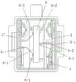
FIG. 1 is an exploded perspective view of example 1 of the present invention;
FIG. 2 is a schematic top view of a base according to embodiment 1 of the present invention;
FIG. 3 is a schematic top view of the embodiment 1 of the present invention with the cover plate removed;
fig. 4 is a schematic perspective view of a cover plate according to embodiment 1 of the present invention;
fig. 5 is a schematic perspective view of a first pin according to embodiment 1 of the present invention;
fig. 6 is a schematic perspective view of a first elastic member according to embodiment 1 of the present invention;
FIG. 7 is a schematic perspective view of an elastic member according to embodiment 1 of the present invention;
fig. 8 is a schematic perspective view of a second pin according to embodiment 1 of the present invention;
FIG. 9 is a schematic view showing a connection structure of a thermistor and respective contact terminals in embodiment 1 of the present invention;
FIG. 10 is a schematic view showing a thermistor in an exploded state according to example 1 of the present invention;
FIG. 11 is a diagram showing a state in which a thermistor of example 1 of the present invention bursts smaller granular fragments;
FIG. 12 is a schematic structural view of example 2 of the present invention;
fig. 13 is a perspective view of a second elastic member according to embodiment 2 of the present invention;
FIG. 14 is a schematic view showing a thermistor in an exploded state according to example 2 of the present invention;
FIG. 15 is a schematic structural view of example 3 of the present invention;
fig. 16 is a schematic diagram of a thermistor burst state according to embodiment 3 of the present invention.
Detailed Description
The present invention will be described in further detail below by way of examples with reference to the accompanying drawings, which are illustrative of the present invention and are not to be construed as limiting the present invention.
Example 1:
referring to fig. 1 to 11, the present embodiment includes a case, a first pin 2, a first elastic member 3, an elastic member 4, a second pin 5, and a thermistor 6. Both the first elastic member 3 and the elastic member 4 employ a spring.
The housing comprises a base 1 and a cover 7. The left side and the right side of the base 1 are respectively provided with a left clamping groove 1-7a and a right clamping groove 1-7b, the left side and the right side of the cover plate 7 are respectively provided with a left clamping jaw 7-3a and a right clamping jaw 7-3b, the left clamping jaw 7-3a is fixedly clamped with the left clamping groove 1-7a, the right clamping jaw 7-3b is fixedly clamped with the right clamping groove 1-7b, and thus the cover plate 7 and the base 1 are fixedly connected.
A thermistor installation cavity 1-1, a first pin installation cavity 1-2, a first elastic piece installation cavity 1-3, an elastic element installation cavity 1-4 and a second pin installation cavity 1-5 are arranged in the base 1. The thermistor 6 is disposed in the thermistor installation cavity 1-1, the first pin 2 is disposed in the first pin installation cavity 1-2, the first elastic member 3 is disposed in the first elastic member installation cavity 1-3, the elastic member 4 is disposed in the elastic member installation cavity 1-4, and the second pin 5 is disposed in the second pin installation cavity 1-5, so that the first pin 2, the first elastic member 3, the elastic member 4, the second pin 5, and the thermistor 6 are disposed on the base 1.
The first pin 2 is provided with a first terminal 2-1, the end of the first terminal 2-1 is provided with a first terminal contact part 2-2, and the first pin 2 and the first terminal 2-1 can be connected integrally or in other connection modes. The first pin 2 is in electrical contact with a first electrode 6-1 of the thermistor 6 through a first terminal contact portion 2-2 provided on the first terminal 2-1.
The first elastic member 3 is provided with a first elastic member contact portion 3-1, and the first elastic member 3 is elastically deformed and then brought into contact with the first electrode 6-1 of the thermistor 6 through the first elastic member contact portion 3-1, which is not in electrical contact. In the normal mounting state of the PTC starter, the elastic force of the first elastic member 3 acting on the thermistor 6 is always larger than the elastic force of the elastic arm 4-3.
The first terminal contact part 2-2 and the first elastic member contact part 3-1 are distributed on both sides of the center line of the elastic member contact part one 4-1 and are distributed opposite to the elastic member contact part one 4-1. The first terminal contact portion 2-2 and the first elastic member contact portion 3-1 are in electrical contact with the edge portion of the thermistor first electrode 6-1.
The second pin 5 is provided with a second pin contact part 5-1.
The elastic element 4 is provided with a fixing sheet 4-4, an elastic arm 4-3 and a connecting sheet 4-5; the fixing piece 4-4 is arranged in the elastic element mounting cavity 1-4; the connecting sheet 4-5 is elastically arranged on the fixing sheet 4-4 through an elastic arm 4-3. Two ends of the connecting sheet 4-5 are provided with a first elastic element contact part 4-1 and a second elastic element contact part 4-2. The spring arm 4-3 is of a resilient construction having a spring force that causes the second spring element contact 4-2 to disengage the second pin contact 5-1 when or after the force applied to the spring element 4 by the thermistor is removed.
The second pin 5 is electrically connected with and disconnected from the second electrode 6-2 of the thermistor 6 through the connecting sheet 4-5; in the normal state of the thermistor 6, the elastic element 4 is in an elastic deformation state, the first elastic element contact part 4-1 is in electrical contact with the middle part of the second electrode 6-2 of the thermistor 6, the second elastic element contact part 4-2 is in electrical contact with the second pin contact part 5-1 to form an electrical loop, the force balance of the thermistor 6 can be kept under the three-point clamping of the first terminal contact part 2-2, the first elastic element contact part 3-1 and the first elastic element contact part 4-1, and the thermistor 6 is fixedly arranged in the thermistor installation cavity 1-1 and is kept in a static state; when the PTC starter is in a failure state, after the thermistor 6 is broken, the force balance state applied to the thermistor 6 by the first terminal contact part 2-2, the first elastic member contact part 3-1 and the elastic element contact part one 4-1 is not existed, the elastic element 4 is elastically reset, at the moment, the connecting piece 4-5 is moved under the elastic reset action of the elastic element elastic arm 4-3, namely, the connecting piece 4-5 is moved under the elastic reset action of the elastic element 4 to push open the broken chip of the thermistor 6, meanwhile, the elastic element contact part two 4-2 is separated from the second pin contact part 5-1, at the moment, the separation distance between the elastic element contact part two 4-2 and the second pin contact part 5-1 is enough to cut off the electric connection between the second pin 5 and the second electrode 6-2 of the thermistor 6, so as to achieve the purpose of cutting off the power-on loop.
An isolation structure for preventing fragments of the thermistor in the thermistor installation cavity 1-1 from splashing into the elastic element installation cavity 1-4 is arranged between the thermistor installation cavity 1-1 and the elastic element installation cavity 1-4, and the isolation structure is fixed in the shell and isolates the thermistor installation cavity 1-1 from the elastic element installation cavity 1-4. The isolation structure can be a partition wall, in the embodiment, the isolation structure comprises a base isolation wall 1-6 and a cover isolation wall 7-2, the base isolation wall 1-6 is fixedly arranged on the base 1, the cover isolation wall 7-2 is fixedly arranged on the cover 7, and after the base isolation wall 1-6 and the cover isolation wall 7-2 are combined, the thermistor installation cavity 1-1 and the elastic element installation cavity 1-4 are isolated.
Referring to fig. 11, when the thermistor 6 is broken and the pieces are in a small particle shape in the PTC starter in a failure state, the elastic member contact portion 4-1 pushes open the broken pieces of the thermistor 6 by the elastic force of the elastic member elastic arm 4-3, and the elastic member contact portion two 4-2 is disengaged from the second pin contact portion 5-1; meanwhile, through the protection effect of the isolation structure, the hidden trouble that small granular fragments in the thermistor installation cavity 1-1 are splashed into the elastic element installation cavity 1-4 to cause the secondary short circuit between the elastic element contact part two 4-2 and the second pin contact part 5-1 is prevented, so that the purpose of improving the reliability of cutting off the electrified loop is achieved.
Example 2:
referring to fig. 12 to 14, which are schematic views of a second embodiment of the present invention, other structures are the same as or similar to those of the first embodiment except for the following differences.
The first pin 2' in the present embodiment removes the first terminal 2-1 and the first terminal contact portion 2-2 in the first embodiment, and the present embodiment removes the first elastic member 3 in the first embodiment and adds the second elastic member 8. The second elastic member 8 is a spring.
The second elastic member 8 is electrically connected with the first pin 2 ', and the second elastic member 8 is elastically provided with a second elastic member contact portion-1 and a second elastic member contact portion-2, wherein under the elastic deformation state of the second elastic member 8, the second elastic member contact portion-8-1 and the second elastic member contact portion-8-2 are both electrically contacted with the first electrode 6-1 of the thermistor 6, so that the first pin 2' is electrically connected with the first electrode 6-1 of the thermistor 6 through the second elastic member 8. The first elastic member contact portion 8-1 and the second elastic member contact portion 8-2 are distributed on both sides of the center line of the first elastic member contact portion 4-1 and are distributed opposite to the first elastic member contact portion 4-1. The first elastic member contact portion 8-1 and the second elastic member contact portion 8-2 are in electrical contact with the edge portion of the thermistor first electrode 6-1. Thus, instead of realizing the functions of the first elastic member contact portion 3-1 and the first terminal contact portion 2-2 in the first embodiment, the thermistor 6 can be held in force balance under three-point clamping of the second elastic member contact portion one 8-1, the second elastic member contact portion two 8-2, and the elastic member contact portion one 4-1 in the normal state of the thermistor 6, and the thermistor 6 is fixedly disposed in the thermistor installation cavity 1-1 and is held in a stationary state.
In this embodiment, the first pin 2' and the second elastic member 8 may be integrally connected, or may be connected in other manners.
Referring to fig. 14, when the thermistor 6 is broken and the fragments are large in a fault state of the PTC starter according to the present invention, the elastic element contact portion 4-1 pushes the broken thermistor 6 fragments away by the elastic force of the elastic element elastic arm 4-3, and the elastic element contact portion two 4-2 is separated from the second pin contact portion 5-1, at which time the distance between the elastic element contact portion two 4-2 and the second pin contact portion 5-1 is enough to cut off the electrical connection between the second pin 5 and the second electrode 6-2 of the thermistor 6, so as to cut off the current-carrying loop; meanwhile, through the protection effect of the isolation structure, the hidden trouble that small granular fragments in the thermistor installation cavity 1-1 are splashed into the elastic element installation cavity 1-4 to cause the secondary short circuit between the elastic element contact part two 4-2 and the second pin contact part 5-1 is prevented, so that the purpose of improving the reliability of cutting off the electrified loop is achieved.
Example 3:
referring to fig. 15, which is a schematic view of a third embodiment of the present invention, the structure is the same as or similar to that of the first embodiment except for the differences described below.
The first pin 2 "in this embodiment is elastically provided with a first terminal 2-1", and the end of the first terminal 2-1 "is provided with a first terminal contact part 2-2".
In this embodiment, the first elastic member 3 in the first embodiment is removed, the supporting member 9 is added, the supporting member 9 is fixedly installed in the base 1, and the supporting member 9 is provided with the supporting member contact portion 9-1.
In the present embodiment, in the elastically deformed state of the first terminal 2-1 ", the first terminal contact portion 2-2" is in electrical contact with the first electrode 6-1 of the thermistor 6, and provides a clamping force; the support piece contact part 9-1 is contacted with the first electrode 6-1 of the thermistor 6 to play a role of support; the first terminal contact portion 2-2 "and the support member contact portion 9-1 are distributed on both sides of the center line of the elastic member contact portion one 4-1 and are distributed opposite to the elastic member contact portion one 4-1; the first terminal contact 2-2 "and the support contact 9-1 are in electrical contact with the edge of the thermistor first electrode 6-1. In the normal state of the thermistor 6, the force balance of the thermistor 6 can be maintained under three-point clamping of the first terminal contact portion 2-2 ", the support member contact portion 9-1, and the elastic member contact portion-4-1, and the thermistor 6 is fixedly disposed in the thermistor installation cavity 1-1 and is maintained in a stationary state.
In this embodiment, the circuit is the same as that in the first embodiment.
Referring to fig. 16, when the PTC starter according to the present invention breaks the thermistor 6 in a failure state, the elastic element contact portion 4-1 pushes away the broken thermistor 6 fragments under the elastic force of the elastic arm 4-3 of the elastic element, and the elastic element contact portion two 4-2 is separated from the second pin contact portion 5-1, at which time the distance between the elastic element contact portion two 4-2 and the second pin contact portion 5-1 is enough to cut off the electrical connection between the second pin 5 and the second electrode 6-2 of the thermistor 6, so as to cut off the current-carrying loop. Meanwhile, through the protection effect of the isolation structure, the hidden trouble that small granular fragments in the thermistor installation cavity 1-1 are splashed into the elastic element installation cavity 1-4 to cause the secondary short circuit between the elastic element contact part two 4-2 and the second pin contact part 5-1 is prevented, so that the purpose of improving the reliability of cutting off the electrified loop is achieved.
The above description is only illustrative of the structure of the present application; moreover, the names of the components of the present application may be different, and all equivalent or simple changes made according to the structure, characteristics and principles described in the present application are included in the protection scope of the present application.
Claims (15)
1. A PTC starter includes a housing, a first pin, a second pin, and a thermistor; the first pin, the second pin and the thermistor are all arranged on the shell; the first pin is electrically connected with a first electrode of the thermistor; a thermistor installation cavity is formed in the shell, and the thermistor is arranged in the thermistor installation cavity; the method is characterized in that: the shell is provided with an elastic element mounting cavity, and the elastic element is mounted in the elastic element mounting cavity; the elastic element is provided with a connecting sheet, and two ends of the connecting sheet are provided with an elastic element contact part I and an elastic element contact part II; the second pin is electrically connected with and disconnected from the second electrode of the thermistor through the connecting sheet; under the normal state of the thermistor, the elastic element is in an elastic deformation state, the first elastic element contact part is electrically contacted with the second electrode of the thermistor, the second elastic element contact part is electrically contacted with the second pin, and the second pin is electrically connected with the second electrode of the thermistor; when the thermistor is broken, the elastic element resets, the connecting piece moves under the action of resetting to jack the broken thermistor, so that the second contact part of the elastic element is separated from the second pin, and the electrical connection between the second pin and the second electrode of the thermistor is cut off; an isolation structure for preventing fragments of the thermistor in the thermistor installation cavity from splashing into the elastic element installation cavity is arranged between the thermistor installation cavity and the elastic element installation cavity.
2. The PTC starter according to claim 1, wherein: the elastic element is also provided with a fixed plate and an elastic arm; the fixing piece is arranged in the elastic element mounting cavity; the connecting piece is elastically arranged on the fixing piece through an elastic arm.
3. The PTC starter according to claim 1, wherein: the isolation structure is an isolation wall which is fixed in the shell and isolates the thermistor installation cavity from the elastic element installation cavity.
4. A PTC starter according to claim 3, wherein: the isolation structure comprises a base isolation wall and a cover plate isolation wall, and after the base isolation wall and the cover plate isolation wall are combined, the thermistor installation cavity and the elastic element installation cavity are isolated.
5. The PTC starter according to claim 1, wherein: the first elastic piece is arranged on the shell; the first elastic piece is provided with a first elastic piece contact part which is contacted with a first electrode of the thermistor; the first pin is provided with a first terminal contact part, and the first pin is electrically contacted with a first electrode of the thermistor through the first terminal contact part to realize the electric connection between the first pin and the first electrode of the thermistor; the thermistor is fixedly arranged in the thermistor installation cavity under three-point clamping of the first terminal contact part, the first elastic piece contact part and the elastic element contact part.
6. The PTC starter according to claim 5, wherein: the first pin is provided with a first terminal, and the first terminal contact part is arranged at the end part of the first terminal.
7. The PTC starter according to claim 1, wherein: the first elastic piece is electrically connected with the first pin, and a first elastic piece contact part and a second elastic piece contact part are arranged on the second elastic piece; and under the three-point clamping of the first second elastic piece contact part, the second elastic piece contact part and the first elastic element contact part, the thermistor is fixedly arranged in the thermistor installation cavity.
8. The PTC starter according to claim 1, wherein: the support is fixedly arranged in the shell, and a support contact part is arranged on the support and is in contact with the first electrode of the thermistor; the first pin is elastically provided with a first terminal, the end part of the first terminal is provided with a first terminal contact part, and the first terminal contact part is electrically contacted with the first electrode of the thermistor to realize the electric connection of the first pin and the first electrode of the thermistor; the thermistor is fixedly arranged in the thermistor installation cavity under three-point clamping of the first terminal contact part, the support piece contact part and the elastic element contact part.
9. The PTC starter according to claim 1, wherein: the second pin is provided with a second pin contact part, and the elastic element contact part passes through the second pin contact part to realize the electric contact and the separation with the second pin.
10. The PTC starter according to claim 7, wherein: and under the condition that the second elastic piece is in an elastic deformation state, the first elastic piece contact part and the second elastic piece contact part are in electric contact with the first electrode of the thermistor.
11. The PTC starter according to claim 8, wherein: the first terminal contact portion is in electrical contact with the thermistor first electrode in the state where the first terminal is elastically deformed.
12. The PTC starter according to claim 5, wherein: the first elastic member contact portion is in contact with the first electrode of the thermistor in a state where the first elastic member is elastically deformed.
13. The PTC starter according to claim 5, wherein: the first elastic element contact part is electrically contacted with the middle part of the second electrode of the thermistor; the first terminal contact part and the first elastic piece contact part are distributed on two sides of a central line of the elastic element contact part and are in electric contact with the edge part of the first electrode of the thermistor.
14. The PTC starter according to claim 7, wherein: the first elastic element contact part is electrically contacted with the middle part of the second electrode of the thermistor; the first elastic piece contact part and the second elastic piece contact part are distributed on two sides of a central line of the first elastic piece contact part and are in electric contact with the edge part of the first electrode of the thermistor.
15. The PTC starter according to claim 8, wherein: the first elastic element contact part is electrically contacted with the middle part of the second electrode of the thermistor; the first terminal contact part and the support part contact part are distributed on two sides of a central line of the elastic element contact part and are in electric contact with the edge part of the first electrode of the thermistor.
Priority Applications (3)
| Application Number | Priority Date | Filing Date | Title |
|---|---|---|---|
| CN202110901499.3A CN113691166B (en) | 2021-08-06 | 2021-08-06 | PTC starter |
| JP2022099307A JP7312496B2 (en) | 2021-08-06 | 2022-06-21 | PTC starter |
| US17/861,275 US11823820B2 (en) | 2021-08-06 | 2022-07-11 | PTC starter |
Applications Claiming Priority (1)
| Application Number | Priority Date | Filing Date | Title |
|---|---|---|---|
| CN202110901499.3A CN113691166B (en) | 2021-08-06 | 2021-08-06 | PTC starter |
Publications (2)
| Publication Number | Publication Date |
|---|---|
| CN113691166A true CN113691166A (en) | 2021-11-23 |
| CN113691166B CN113691166B (en) | 2023-06-13 |
Family
ID=78579062
Family Applications (1)
| Application Number | Title | Priority Date | Filing Date |
|---|---|---|---|
| CN202110901499.3A Active CN113691166B (en) | 2021-08-06 | 2021-08-06 | PTC starter |
Country Status (3)
| Country | Link |
|---|---|
| US (1) | US11823820B2 (en) |
| JP (1) | JP7312496B2 (en) |
| CN (1) | CN113691166B (en) |
Families Citing this family (1)
| Publication number | Priority date | Publication date | Assignee | Title |
|---|---|---|---|---|
| CN116683414A (en) * | 2023-07-17 | 2023-09-01 | 兰溪市越强电器有限公司 | A safety starter |
Citations (8)
| Publication number | Priority date | Publication date | Assignee | Title |
|---|---|---|---|---|
| JP2004274896A (en) * | 2003-03-10 | 2004-09-30 | Texas Instr Japan Ltd | Motor starter |
| CN101826825A (en) * | 2009-09-07 | 2010-09-08 | 张家港华捷电子有限公司 | Compressor motor starter |
| CN202019325U (en) * | 2011-04-01 | 2011-10-26 | 艾新(苏州)电子控制器件有限公司 | Starter for failure safety motor |
| CN102497137A (en) * | 2011-12-05 | 2012-06-13 | 杭州星帅尔电器股份有限公司 | Three-point contact type starter |
| JP2013038954A (en) * | 2011-08-09 | 2013-02-21 | Murata Mfg Co Ltd | Motor starting circuit |
| CN202957779U (en) * | 2012-11-07 | 2013-05-29 | 杭州星帅尔电器股份有限公司 | Structure-improved electronic starter |
| CN104362906A (en) * | 2014-07-15 | 2015-02-18 | 杭州星帅尔电器股份有限公司 | Starter with temperature fuse |
| CN208623492U (en) * | 2018-08-24 | 2019-03-19 | 广州森宝电器股份有限公司 | A kind of compressor PTC starter |
Family Cites Families (10)
| Publication number | Priority date | Publication date | Assignee | Title |
|---|---|---|---|---|
| JPH0582303A (en) * | 1991-09-19 | 1993-04-02 | Zexel Corp | PTC thermistor |
| KR100231796B1 (en) * | 1995-11-07 | 1999-12-01 | 무라타 야스타카 | Electronic devices reduced destruction of internl elements upon malfunction |
| JP2891179B2 (en) * | 1996-05-10 | 1999-05-17 | 株式会社村田製作所 | Electronic components |
| JPH10149906A (en) * | 1996-09-20 | 1998-06-02 | Tdk Corp | PTC element holding structure |
| US20080315983A1 (en) * | 2005-07-11 | 2008-12-25 | Byoung-Koo Oh | Safety Device For Preventing Propagation in Fracture of Ceramic Element |
| US8174354B2 (en) * | 2010-07-23 | 2012-05-08 | Sensata Technologies Massachusetts, Inc. | Method and apparatus for control of failed thermistor devices |
| CN103489551B (en) | 2012-06-14 | 2018-06-12 | 森萨塔科技(常州)有限公司 | Electronic device |
| EP2674949B1 (en) * | 2012-06-14 | 2018-08-29 | Sensata Technologies, Inc. | PTC device with casing and means for breaking contact in case of failure |
| CN202615954U (en) * | 2012-06-14 | 2012-12-19 | 森萨塔科技麻省公司 | Electronic device |
| US10984927B2 (en) * | 2019-05-03 | 2021-04-20 | Electrica S.R.L. | PTC thermistor switch for electric motors |
-
2021
- 2021-08-06 CN CN202110901499.3A patent/CN113691166B/en active Active
-
2022
- 2022-06-21 JP JP2022099307A patent/JP7312496B2/en active Active
- 2022-07-11 US US17/861,275 patent/US11823820B2/en active Active
Patent Citations (8)
| Publication number | Priority date | Publication date | Assignee | Title |
|---|---|---|---|---|
| JP2004274896A (en) * | 2003-03-10 | 2004-09-30 | Texas Instr Japan Ltd | Motor starter |
| CN101826825A (en) * | 2009-09-07 | 2010-09-08 | 张家港华捷电子有限公司 | Compressor motor starter |
| CN202019325U (en) * | 2011-04-01 | 2011-10-26 | 艾新(苏州)电子控制器件有限公司 | Starter for failure safety motor |
| JP2013038954A (en) * | 2011-08-09 | 2013-02-21 | Murata Mfg Co Ltd | Motor starting circuit |
| CN102497137A (en) * | 2011-12-05 | 2012-06-13 | 杭州星帅尔电器股份有限公司 | Three-point contact type starter |
| CN202957779U (en) * | 2012-11-07 | 2013-05-29 | 杭州星帅尔电器股份有限公司 | Structure-improved electronic starter |
| CN104362906A (en) * | 2014-07-15 | 2015-02-18 | 杭州星帅尔电器股份有限公司 | Starter with temperature fuse |
| CN208623492U (en) * | 2018-08-24 | 2019-03-19 | 广州森宝电器股份有限公司 | A kind of compressor PTC starter |
Also Published As
| Publication number | Publication date |
|---|---|
| US20230039950A1 (en) | 2023-02-09 |
| JP7312496B2 (en) | 2023-07-21 |
| US11823820B2 (en) | 2023-11-21 |
| CN113691166B (en) | 2023-06-13 |
| JP2023024284A (en) | 2023-02-16 |
Similar Documents
| Publication | Publication Date | Title |
|---|---|---|
| US5729416A (en) | Motor starter and protector module | |
| CA1131300A (en) | Combination starter-protector device | |
| CN110739194A (en) | Circuit breaker test device and circuit breaker with the same | |
| CN113691166B (en) | PTC starter | |
| CN215897616U (en) | PTC starter with connection and disconnection structure | |
| CN215897617U (en) | PTC starter with isolation structure | |
| CN219811439U (en) | Combined starting thermal protector | |
| CN210778468U (en) | Circuit breaker testing device and circuit breaker with same | |
| CN220106413U (en) | Contact structure | |
| CN216056837U (en) | Three-point contact PTC starter | |
| CN214707572U (en) | Short-circuit-proof PTC starter | |
| CN221446898U (en) | Thermistor starter | |
| CN202406072U (en) | Three-point-contact type starter | |
| US3694717A (en) | Starting and overload control device for electric motors | |
| CN216122255U (en) | Starter | |
| CN218449902U (en) | Small PTC starter and starting thermal protector | |
| CN223141511U (en) | Improved integrated starter protector structure | |
| CN218730767U (en) | Static contact for molded case circuit breaker | |
| CN223140689U (en) | A leakage circuit breaker and electrical system | |
| CN202285383U (en) | Electronic starter | |
| CN220895440U (en) | Contact structure and circuit breaker | |
| CN223501786U (en) | An environmentally friendly cabinet circuit breaker | |
| CN215268102U (en) | Safety starter | |
| CN219124118U (en) | Multi-terminal heavy hammer starter | |
| CN217933675U (en) | Tripping device for control and protection switch |
Legal Events
| Date | Code | Title | Description |
|---|---|---|---|
| PB01 | Publication | ||
| PB01 | Publication | ||
| SE01 | Entry into force of request for substantive examination | ||
| SE01 | Entry into force of request for substantive examination | ||
| GR01 | Patent grant | ||
| GR01 | Patent grant |