CN113623498A - Portable device support device and wireless charger - Google Patents

Portable device support device and wireless charger Download PDF

Info

Publication number
CN113623498A
CN113623498A CN202111079283.XA CN202111079283A CN113623498A CN 113623498 A CN113623498 A CN 113623498A CN 202111079283 A CN202111079283 A CN 202111079283A CN 113623498 A CN113623498 A CN 113623498A
Authority
CN
China
Prior art keywords
support
main body
portable device
pin
supporting
Prior art date
Legal status (The legal status is an assumption and is not a legal conclusion. Google has not performed a legal analysis and makes no representation as to the accuracy of the status listed.)
Granted
Application number
CN202111079283.XA
Other languages
Chinese (zh)
Other versions
CN113623498B (en
Inventor
任黎明
Current Assignee (The listed assignees may be inaccurate. Google has not performed a legal analysis and makes no representation or warranty as to the accuracy of the list.)
E&c Smart Link Technology Co ltd
Original Assignee
E&c Smart Link Technology Co ltd
Priority date (The priority date is an assumption and is not a legal conclusion. Google has not performed a legal analysis and makes no representation as to the accuracy of the date listed.)
Filing date
Publication date
Application filed by E&c Smart Link Technology Co ltd filed Critical E&c Smart Link Technology Co ltd
Priority to CN202111079283.XA priority Critical patent/CN113623498B/en
Publication of CN113623498A publication Critical patent/CN113623498A/en
Application granted granted Critical
Publication of CN113623498B publication Critical patent/CN113623498B/en
Active legal-status Critical Current
Anticipated expiration legal-status Critical

Links

Images

Classifications

    • F—MECHANICAL ENGINEERING; LIGHTING; HEATING; WEAPONS; BLASTING
    • F16—ENGINEERING ELEMENTS AND UNITS; GENERAL MEASURES FOR PRODUCING AND MAINTAINING EFFECTIVE FUNCTIONING OF MACHINES OR INSTALLATIONS; THERMAL INSULATION IN GENERAL
    • F16M—FRAMES, CASINGS OR BEDS OF ENGINES, MACHINES OR APPARATUS, NOT SPECIFIC TO ENGINES, MACHINES OR APPARATUS PROVIDED FOR ELSEWHERE; STANDS; SUPPORTS
    • F16M11/00—Stands or trestles as supports for apparatus or articles placed thereon ; Stands for scientific apparatus such as gravitational force meters
    • F16M11/02—Heads
    • F16M11/04—Means for attachment of apparatus; Means allowing adjustment of the apparatus relatively to the stand
    • F16M11/043—Allowing translations
    • F—MECHANICAL ENGINEERING; LIGHTING; HEATING; WEAPONS; BLASTING
    • F16—ENGINEERING ELEMENTS AND UNITS; GENERAL MEASURES FOR PRODUCING AND MAINTAINING EFFECTIVE FUNCTIONING OF MACHINES OR INSTALLATIONS; THERMAL INSULATION IN GENERAL
    • F16M—FRAMES, CASINGS OR BEDS OF ENGINES, MACHINES OR APPARATUS, NOT SPECIFIC TO ENGINES, MACHINES OR APPARATUS PROVIDED FOR ELSEWHERE; STANDS; SUPPORTS
    • F16M11/00—Stands or trestles as supports for apparatus or articles placed thereon ; Stands for scientific apparatus such as gravitational force meters
    • F16M11/02—Heads
    • F16M11/04—Means for attachment of apparatus; Means allowing adjustment of the apparatus relatively to the stand
    • F16M11/06—Means for attachment of apparatus; Means allowing adjustment of the apparatus relatively to the stand allowing pivoting
    • F16M11/10—Means for attachment of apparatus; Means allowing adjustment of the apparatus relatively to the stand allowing pivoting around a horizontal axis
    • H—ELECTRICITY
    • H02—GENERATION; CONVERSION OR DISTRIBUTION OF ELECTRIC POWER
    • H02J—ELECTRIC POWER NETWORKS; CIRCUIT ARRANGEMENTS OR SYSTEMS FOR SUPPLYING OR DISTRIBUTING ELECTRIC POWER; SYSTEMS FOR STORING ELECTRIC ENERGY
    • H02J50/00—Circuit arrangements or systems for wireless supply or distribution of electric power
    • H02J50/005—Mechanical details of housing or structure aiming to accommodate the power transfer means, e.g. mechanical integration of coils, antennas or transducers into emitting or receiving devices
    • H—ELECTRICITY
    • H02—GENERATION; CONVERSION OR DISTRIBUTION OF ELECTRIC POWER
    • H02J—ELECTRIC POWER NETWORKS; CIRCUIT ARRANGEMENTS OR SYSTEMS FOR SUPPLYING OR DISTRIBUTING ELECTRIC POWER; SYSTEMS FOR STORING ELECTRIC ENERGY
    • H02J7/00—Circuit arrangements for charging or discharging batteries or for supplying loads from batteries
    • H02J7/70—Circuit arrangements for charging or discharging batteries or for supplying loads from batteries characterised by the mechanical construction
    • H02J7/731—Circuit arrangements for charging or discharging batteries or for supplying loads from batteries characterised by the mechanical construction specially adapted for holding portable devices containing batteries

Landscapes

  • Engineering & Computer Science (AREA)
  • General Engineering & Computer Science (AREA)
  • Power Engineering (AREA)
  • Mechanical Engineering (AREA)
  • Computer Networks & Wireless Communication (AREA)
  • Telephone Set Structure (AREA)

Abstract

本发明涉及便携设备支撑装置及无线充电器。该便携设备支撑装置包括主体(10)和支架(30),所述支架(30)包括第一支撑件(40)和第二支撑件(50);所述第一支撑件(40)可转动地连接到所述主体(10)且可相对于所述主体(10)从第一位置转动到第二位置,在所述第一位置时贴靠所述主体(10);所述第二支撑件(50)可转动地连接到所述第一支撑件(40)且可相对于所述第一支撑件(40)从第三位置转动到第四位置,在所述第三位置时贴靠所述第一支撑件(40);所述第一支撑件(40)稳定在所述第二位置时,所述便携设备支撑装置可通过所述支架(30)与所述主体(10)稳定放置便携设备。该便携设备支撑装置的支架可折叠到主体,结构紧凑,携带方便。

Figure 202111079283

The present invention relates to a portable device supporting device and a wireless charger. The portable device supporting device includes a main body (10) and a bracket (30), the bracket (30) includes a first support (40) and a second support (50); the first support (40) is rotatable groundly connected to the body (10) and rotatable relative to the body (10) from a first position to a second position in which it abuts the body (10); the second support A member (50) is rotatably connected to the first support (40) and is rotatable relative to the first support (40) from a third position to a fourth position in which it abuts The first supporting member (40); when the first supporting member (40) is stabilized in the second position, the portable device supporting device can be stabilized with the main body (10) through the bracket (30) Place portable devices. The bracket of the portable device supporting device can be folded to the main body, has a compact structure and is convenient to carry.

Figure 202111079283

Description

Portable device supporting device and wireless charger
[ technical field ] A method for producing a semiconductor device
The invention relates to the field of peripheral accessories of digital products, in particular to a portable equipment supporting device and a wireless charger.
[ background of the invention ]
Portable devices such as mobile phones, tablet computers, smart wristwatches, and the like are becoming more and more popular. Users often need a support stand to facilitate use of the device on a table. The existing support bracket has large volume and is inconvenient to carry and use. Therefore, a need exists for an improved solution.
[ summary of the invention ]
An object of the present invention is to reduce the volume of a portable device supporting apparatus.
To this end, in a first aspect of the present invention, there is provided a portable device supporting apparatus including a main body for connecting a portable device and a stand connected to the main body, wherein: the bracket comprises a first support and a second support; the first support is rotatably connected to the main body, the first support can rotate relative to the main body from a first position to a second position, the first support is abutted against the main body when in the first position, and forms a first included angle with the main body when in the second position; the second support member is rotatably connected to the first support member, the second support member is rotatable relative to the first support member from a third position, in which the second support member abuts the first support member, to a fourth position, in which the second support member forms a second included angle with the first support member; the portable device support apparatus further has a first positioning structure for stabilizing the first support member in the second position and a second positioning structure for stabilizing the second support member in the fourth position; when the first supporting piece is stabilized at the second position, the portable equipment supporting device can stably place portable equipment through the bracket and the main body.
In one embodiment, the first support rotates relative to the body about a first axis; the second support rotates relative to the first support about a second axis that is offset from the first axis; when the first support is stable at the second position and the second support is stable at the fourth position, the portable equipment supporting device can be stably placed with the main body through the second support.
In one embodiment, the first supporting piece is arc-shaped, the main body is provided with a concave arc-shaped first accommodating position, and the first supporting piece is accommodated in the first accommodating position when in the first position; the second support piece is arc-shaped, one side of the first support piece is provided with a concave arc-shaped second accommodating position, and the second support piece is accommodated in the second accommodating position when in the third position.
In one embodiment, the first support of the portable device is connected to the main body through a first pin, and the first pin is slightly matched to form the first positioning structure.
In one embodiment, the first supporting member is connected to the main body through a first pin, a plurality of discrete first positioning protrusions are arranged on the surface of the first pin, a plurality of corresponding discrete first concave positions are arranged at the position for accommodating the first pin, and the first concave positions and the first protrusions are matched to form the first positioning structure.
In one embodiment, the second support is connected to the first support by a second pin, and the second pin is a slight fit to form the second positioning structure.
In one embodiment, the second supporting member is connected to the first supporting member by a second pin, the surface of the second pin is provided with a plurality of discrete second positioning protrusions, a portion for accommodating the second pin is provided with a plurality of corresponding discrete second concave portions, and the second concave portions and the second protrusions are matched to form the second positioning structure.
In one embodiment, a magnetic attraction structure is arranged inside the main body and used for attracting the surface of the portable device.
In one embodiment, the main body is an oblate body, and the bracket is positioned on the back surface of the main body; when the first supporting piece is located at the first position and the second supporting piece is located at the third position, the bracket is attached to the main body and is flush with the back surface of the main body.
The second aspect of the present invention provides a wireless charging device, comprising a wireless charging module and the portable device supporting apparatus provided in the first aspect of the present invention, wherein the wireless charging module is installed in the main body, and a power input port of the wireless charging module is disposed in the main body.
By implementing the invention, the bracket of the portable equipment supporting device can be folded to the surface of the main body, thereby having a compact structure and being convenient to carry and use.
[ description of the drawings ]
Fig. 1 is a perspective view of a wireless charger according to a first embodiment of the present invention;
fig. 2 is a perspective view of another perspective of the wireless charger of fig. 1;
FIG. 3 is an exploded view of the wireless charger of FIG. 2;
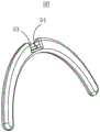
fig. 4 is a partial schematic view of a first support of a wireless charger according to a second embodiment of the invention;
fig. 5 is a schematic view of a second supporting member of the wireless charger according to the second embodiment of the present invention.
[ detailed description ] embodiments
The invention is further described below with reference to the figures and examples.
As shown in fig. 1 and 2, a wireless charger 100 according to a first embodiment of the present invention includes a wireless charging module and a portable device supporting apparatus including a main body 10 for connecting a portable device and a cradle 30 connected to the main body 10, the wireless charging module being mounted in the main body 10, and a power input port 15 of the wireless charging module being provided in the main body 10. The wireless charging module used in the invention is the prior art, and therefore, the specific structure of the wireless charging module is not described again.
The body 10 is oblate and has a front face 11 and a back face 13 which are relatively flat. The main body 10 is provided with a magnetic structure inside, so that the front surface 1 can be attached to the surface of the portable device, thereby being stably connected with the portable device. In this embodiment, the magnetic attraction structure is a plurality of arc magnets, and the arc magnets surround a ring and surround the wireless charging module.
The bracket 30 includes a first support 40 and a second support 50. The first support 40 is rotatably connected to the back 13 of the main body 10, the first support 40 can rotate relative to the main body 10 from a first position to a second position, the first support 40 abuts against the back 13 of the main body 10 in the first position, and forms a first included angle with the main body 10 in the second position; the second support member 50 is rotatably connected to the first support member 40, and the second support member 50 is rotatable relative to the first support member 40 from a third position, in which the second support member 50 abuts the first support member 40, to a fourth position, in which the second support member 50 forms a second angle with the first support member 40.
The portable device support apparatus also has a first locating feature for stabilizing the first support member 40 in the second position and a second locating feature for stabilizing the second support member 50 in the fourth position.
When the first support 40 is stabilized at the second position, the stand 30 and the main body 10 can be stably placed on the bearing surface to support the portable device through the main body 10. More specifically, when the first supporting member 40 is stabilized at the second position and the second supporting member 50 is stabilized at the fourth position, the second supporting member 50 and the main body 10 can be stably placed on the carrying surface.
Referring to fig. 1 to 3, the first supporting member 40 rotates around a first axis relative to the main body 10; the second support 50 rotates relative to the first support 40 about a second axis that is offset from the first axis. In the present embodiment, the first supporting member 40 has an arc shape. Both ends of the first supporter 40 are provided with first pins 43 protruding inward, and are rotatably connected to both sides of the main body 10 by the first pins 43. The main body 10 is provided with a concave arc-shaped first receiving position 17, and the first supporting member 40 is received in the first receiving position 17 when in the first position. The second supporting member 50 has an arc shape, and a middle portion of the second supporting member 50 is rotatably connected to a middle portion of the first supporting member 40, and both ends of the second supporting member 50 serve as supporting legs. One side of the first supporting member 40 is provided with a concave arc-shaped second receiving position 47, and the second supporting member 50 is received in the second receiving position at the third position. Understandably, when the first supporting member 40 is located at the first position and the second supporting member 50 is located at the third position, the bracket 30 is abutted against the main body 10 and is flush with the back surface 13 of the main body 10.
In this embodiment, a shaft hole 16 is provided in a side surface of the oblate body 10. The first supporting member 40 is connected to the first shaft hole 16 of the main body 10 by a first pin 43, and the first pin 43 is slightly fitted with the first shaft hole 16 to form a first positioning structure. The middle of the first supporting member 40 is provided with a second shaft hole 46, the second supporting member 50 is connected to the second shaft hole 46 of the first supporting member 40 through a second pin 53, and the second pin 53 and the second shaft hole 46 are in a slightly tight fit to form a second positioning structure. The stand 30 is stabilized in a position desired by a user by the first and second positioning structures, thereby forming a stable structure with the main body 10 for supporting the portable device thereon.
As shown in fig. 4 and 5, in the second embodiment, the first support 40 is connected to the main body 10 by a first pin 43, and the first pin 43 is provided at a surface thereof with a plurality of discrete first positioning protrusions 44, and the plurality of first positioning protrusions 44 are arranged along a circumferential direction of the first pin 43. Correspondingly, the portion of the main body 10 that accommodates the first pin 43, for example, the inner wall of the first shaft hole 16, is provided with a plurality of discrete first concave portions, and the first concave portions cooperate with the first protrusions 44 to form the first positioning structure. As such, the first support 40 may be stabilized in several positions with respect to the main body 10, thereby enabling control of the degree of inclination of the main body 10.
Similarly, the second support 50 is connected to the first support 40 by a second pin 53, and the second pin 53 is provided with a plurality of discrete second positioning protrusions 54 on the surface thereof, and the plurality of second positioning protrusions 54 are arranged along the circumferential direction of the second pin 53. Correspondingly, the portion for receiving the second pin 53, for example, the inner wall of the second shaft hole 46, is provided with a plurality of discrete second concave locations, and the second concave locations and the second convex blocks 54 cooperate to form a second positioning structure. As such, the second support 50 may be stabilized in several positions with respect to the first support 40, thereby cooperating with the first support 40 to control the degree of inclination of the body 10.
The above examples merely represent preferred embodiments of the present invention, which are described in more detail and detail, but are not to be construed as limiting the scope of the present invention. It should be noted that, for a person skilled in the art, several variations and modifications, such as combinations of different features in various embodiments, may be made without departing from the spirit of the invention, and these are within the scope of the invention.

Claims (10)

1.一种便携设备支撑装置,其特征在于,包括用于连接便携设备的主体(10)和连接所述主体(10)的支架(30),其中:1. A portable device support device, characterized in that it comprises a main body (10) for connecting a portable device and a bracket (30) for connecting the main body (10), wherein: 所述支架(30)包括第一支撑件(40)和第二支撑件(50);所述第一支撑件(40)可转动地连接到所述主体(10),所述第一支撑件(40)可相对于所述主体(10)从第一位置转动到第二位置,所述第一支撑件(40)在所述第一位置时贴靠所述主体(10),在所述第二位置时与所述主体(10)形成第一夹角;所述第二支撑件(50)可转动地连接到所述第一支撑件(40),所述第二支撑件(50)可相对于所述第一支撑件(40)从第三位置转动到第四位置,所述第二支撑件(50)在所述第三位置时贴靠所述第一支撑件(40),在所述第四位置时与所述第一支撑件(40)形成第二夹角;The bracket (30) includes a first support (40) and a second support (50); the first support (40) is rotatably connected to the main body (10), the first support (40) is rotatable relative to the main body (10) from a first position to a second position, in which the first support (40) abuts the main body (10), in the first position In the second position, a first angle is formed with the main body (10); the second support (50) is rotatably connected to the first support (40), and the second support (50) can be rotated relative to the first support (40) from a third position to a fourth position, and the second support (50) abuts against the first support (40) in the third position, In the fourth position, a second angle is formed with the first support (40); 所述便携设备支撑装置还具有第一定位结构和第二定位结构,所述第一限位结构用于将所述第一支撑件(40)稳定在所述第二位置,所述第二限位结构用于将所述第二支撑件(50)稳定在所述第四位置;The portable device supporting device further has a first positioning structure and a second positioning structure, the first limiting structure is used for stabilizing the first support member (40) at the second position, and the second limiting structure is a position structure for stabilizing the second support (50) in the fourth position; 所述第一支撑件(40)稳定在所述第二位置时,所述便携设备支撑装置可通过所述支架(30)与所述主体(10)稳定放置便携设备。When the first support member (40) is stabilized at the second position, the portable device support device can stably place the portable device through the bracket (30) and the main body (10). 2.如权利要求1所述的便携设备支撑装置,其特征在于,所述第一支撑件(40)绕着第一轴线相对于所述主体(10)转动;所述第二支撑件(50)绕着第二轴线相对于所述第一支撑件(40)转动,所述第二轴线偏离所述第一轴线;所述第一支撑件(40)稳定在所述第二位置且所述第二支撑件(50)稳定在所述第四位置时,所述便携设备支撑装置可通过所述第二支撑件(50)与所述主体(10)稳定放置。2. The portable device supporting device according to claim 1, wherein the first support member (40) rotates relative to the main body (10) around a first axis; the second support member (50) ) rotates relative to said first support (40) about a second axis, said second axis being offset from said first axis; said first support (40) is stabilized in said second position and said When the second support (50) is stabilized in the fourth position, the portable device support device can be stably placed with the main body (10) through the second support (50). 3.如权利要求2所述的便携设备支撑装置,其特征在于,所述第一支撑件(40)为弧形,所述第一支撑件(40)的两端连接到所述主体(10),所述主体(10)设有凹陷的弧形的第一收容位,所述第一支撑件(40)在所述第一位置时收容在所述第一收容位;所述第二支撑件(50)为弧形,所述第二支撑件(40)的中部连接到所述第一支撑件(40)的中部,所述第一支撑件(40)的一侧设有凹陷的弧形的第二收容位,所述第二支撑件(50)在所述第三位置时收容在所述第二收容位。3. The portable device support device according to claim 2, wherein the first support member (40) is arc-shaped, and both ends of the first support member (40) are connected to the main body (10). ), the main body (10) is provided with a concave arc-shaped first receiving position, and the first support member (40) is housed in the first receiving position when the first position is located; the second support The member (50) is arc-shaped, the middle portion of the second support member (40) is connected to the middle portion of the first support member (40), and a side of the first support member (40) is provided with a concave arc The second accommodating position is in the shape of the second accommodating position, and the second supporting member (50) is accommodated in the second accommodating position when the second supporting member (50) is in the third position. 4.如权利要求1所述的便携设备支撑装置,其特征在于,所述第一支撑件(40)通过第一销轴(43)连接到所述主体(10),所述第一销轴(43)为微紧配从而形成所述第一定位结构。4. The portable device support device according to claim 1, wherein the first support member (40) is connected to the main body (10) through a first pin (43), the first pin (43) is a micro-tight fit to form the first positioning structure. 5.如权利要求1所述的便携设备支撑装置,其特征在于,所述第一支撑件(40)通过第一销轴(43)连接到所述主体(10),所述第一销轴(43)表面设置有若干离散的第一定位凸块(44),收容所述第一销轴(43)的部位设有对应的若干离散的第一凹位,所述第一凹位与所述第一凸块(44)配合形成所述第一定位结构。5. The portable device support device according to claim 1, wherein the first support member (40) is connected to the main body (10) through a first pin (43), the first pin (43) A number of discrete first positioning bumps (44) are provided on the surface, and a number of discrete first concave positions corresponding to the part containing the first pin shaft (43) are provided, and the first concave positions are connected to the The first bumps (44) cooperate to form the first positioning structure. 6.如权利要求1所述的便携设备支撑装置,其特征在于,所述第二支撑件(50)通过第二销轴(53)连接到所述第一支撑件(40),所述第二销轴(53)为微紧配从而形成所述第二定位结构。6. The portable device supporting device according to claim 1, wherein the second supporting member (50) is connected to the first supporting member (40) through a second pin (53), and the first supporting member (50) is The two pin shafts (53) are tightly fitted to form the second positioning structure. 7.如权利要求1所述的便携设备支撑装置,其特征在于,所述第二支撑件(50)通过第二销轴(53)连接到所述第一支撑件(40),所述第二销轴(53)表面设置有若干离散的第二定位凸块(54),收容所述第二销轴(53)的部位设有对应的若干离散的第二凹位,所述第二凹位与所述第二凸块(54)配合形成所述第二定位结构。7. The portable device supporting device according to claim 1, wherein the second supporting member (50) is connected to the first supporting member (40) through a second pin (53), and the first supporting member (50) is The surfaces of the two pin shafts (53) are provided with a number of discrete second positioning bumps (54), and the part that accommodates the second pin shaft (53) is provided with a corresponding number of discrete second recesses, the second recesses The second positioning structure is formed by cooperating with the second bump (54). 8.如权利要求1所述的便携设备支撑装置,其特征在于,所述主体(10)内部设有磁吸结构用于吸附到所述便携设备的表面。8. The portable device support device according to claim 1, characterized in that, a magnetic attraction structure is provided inside the main body (10) for being adsorbed to the surface of the portable device. 9.如权利要求1所述的便携设备支撑装置,其特征在于,所述主体(10)为扁圆体,所述支架(30)位于所述主体(10)的背面;所述第一支撑件(40)位于所述第一位置且所述第二支撑件(50)位于所述第三位置时,所述支架(30)贴靠所述主体(10)并与所述主体(10)的背面平齐。9. The portable device support device according to claim 1, characterized in that, the main body (10) is an oblate, the bracket (30) is located on the back of the main body (10); the first support When the member (40) is in the first position and the second support member (50) is in the third position, the bracket (30) is abutted against the main body (10) and is in contact with the main body (10) the back is flush. 10.一种无线充电装置,包括无线充电模块,其特征在于,还包括如权利要求1至9中任意一项所述的便携设备支撑装置,所述无线充电模块安装到所述主体(10)内,所述无线充电模块的电源输入口(15)设置在所述主体(10)。10. A wireless charging device, comprising a wireless charging module, characterized by further comprising the portable device supporting device according to any one of claims 1 to 9, wherein the wireless charging module is mounted to the main body (10) Inside, the power input port (15) of the wireless charging module is arranged on the main body (10).
CN202111079283.XA 2021-09-15 2021-09-15 Portable device support device and wireless charger Active CN113623498B (en)

Priority Applications (1)

Application Number Priority Date Filing Date Title
CN202111079283.XA CN113623498B (en) 2021-09-15 2021-09-15 Portable device support device and wireless charger

Applications Claiming Priority (1)

Application Number Priority Date Filing Date Title
CN202111079283.XA CN113623498B (en) 2021-09-15 2021-09-15 Portable device support device and wireless charger

Publications (2)

Publication Number Publication Date
CN113623498A true CN113623498A (en) 2021-11-09
CN113623498B CN113623498B (en) 2024-07-12

Family

ID=78390065

Family Applications (1)

Application Number Title Priority Date Filing Date
CN202111079283.XA Active CN113623498B (en) 2021-09-15 2021-09-15 Portable device support device and wireless charger

Country Status (1)

Country Link
CN (1) CN113623498B (en)

Cited By (1)

* Cited by examiner, † Cited by third party
Publication number Priority date Publication date Assignee Title
US20220407353A1 (en) * 2021-06-21 2022-12-22 Cheng Uei Precision Industry Co., Ltd. Wireless charger

Citations (6)

* Cited by examiner, † Cited by third party
Publication number Priority date Publication date Assignee Title
US20150034781A1 (en) * 2013-07-31 2015-02-05 Samsung Electronics Co., Ltd. Portable foldable cradle
CN104565696A (en) * 2013-10-28 2015-04-29 富泰华工业(深圳)有限公司 Portable bracket
DE202015106250U1 (en) * 2015-08-07 2016-01-18 Coremate Technical Co., Ltd. A portable multi-purpose charger suitable for wireless charging of electronic devices
DE202018002286U1 (en) * 2018-05-08 2018-06-01 Eagle Fan Adjustable wireless charging device
CN209375195U (en) * 2019-02-26 2019-09-10 深圳市沃客非凡科技有限公司 Charging panel can stand portable mobile wireless cradle
CN216479711U (en) * 2021-09-15 2022-05-10 深圳市和鑫晟智连科技有限公司 Portable device supporting device and wireless charger

Patent Citations (6)

* Cited by examiner, † Cited by third party
Publication number Priority date Publication date Assignee Title
US20150034781A1 (en) * 2013-07-31 2015-02-05 Samsung Electronics Co., Ltd. Portable foldable cradle
CN104565696A (en) * 2013-10-28 2015-04-29 富泰华工业(深圳)有限公司 Portable bracket
DE202015106250U1 (en) * 2015-08-07 2016-01-18 Coremate Technical Co., Ltd. A portable multi-purpose charger suitable for wireless charging of electronic devices
DE202018002286U1 (en) * 2018-05-08 2018-06-01 Eagle Fan Adjustable wireless charging device
CN209375195U (en) * 2019-02-26 2019-09-10 深圳市沃客非凡科技有限公司 Charging panel can stand portable mobile wireless cradle
CN216479711U (en) * 2021-09-15 2022-05-10 深圳市和鑫晟智连科技有限公司 Portable device supporting device and wireless charger

Cited By (1)

* Cited by examiner, † Cited by third party
Publication number Priority date Publication date Assignee Title
US20220407353A1 (en) * 2021-06-21 2022-12-22 Cheng Uei Precision Industry Co., Ltd. Wireless charger

Also Published As

Publication number Publication date
CN113623498B (en) 2024-07-12

Similar Documents

Publication Publication Date Title
US20230291822A1 (en) Magnetic type mobile phone holder
JP5841456B2 (en) Cradle device
TWI512428B (en) Supporting device and electronic apparatus using the same
CN103162072B (en) Support device
TWI531887B (en) Dock station and electronic device assembly using the same
US9194536B2 (en) Portable foldable cradle
US20120168577A1 (en) Shell for electronic device
TWI550386B (en) Detachable display member with support member
CN103312846A (en) Universal dock for portable phone
TW201115306A (en) Positioning standing and electrical apparatus having the same
TWM488833U (en) Data device with USB connector
CN113623498B (en) Portable device support device and wireless charger
CN216479711U (en) Portable device supporting device and wireless charger
CN108258774A (en) Wireless charger with support structure
CN214900954U (en) Support, protective housing and electronic equipment
CN220340604U (en) Tablet personal computer protective sleeve capable of magnetically attracting mobile phone
CN211551068U (en) A folding support for intelligent terminal
KR101992297B1 (en) Charging Cable For Mobile Device
KR20120008365U (en) Supporting case for display device
CN117879111A (en) A wireless charging stand with good compatibility
KR200488289Y1 (en) Stand of portable terminal
CN103672318B (en) Support and there is the electronic installation of this support
CN221202609U (en) Electronic equipment support and accessory
CN220570001U (en) a socket
CN220858144U (en) High-applicability ring support and mobile phone shell thereof

Legal Events

Date Code Title Description
PB01 Publication
PB01 Publication
SE01 Entry into force of request for substantive examination
GR01 Patent grant
GR01 Patent grant