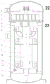
Scroll compressor
Technical Field
The invention relates to the technical field of scroll compressors, in particular to a scroll compressor.
Background
For a scroll compressor, a casing includes a shell, an upper cover, and a lower cover, and each of working components is installed in the casing. General motor stator is fixed in the shell through external fixed ring, the shell upper end sets up and contains the main bearing and is used for supporting the last support that moves the vortex, the lower extreme sets up the lower support that contains the auxiliary bearing, the drive moves the bent axle of vortex motion and passes main, the auxiliary bearing, the event is main, the axiality of auxiliary bearing has vital effect to the compressor operation, the axiality is poor, light then the compressor entry increases, the life-span descends, heavy then the unable operation of compressor leads to scrapping, traditional owner, auxiliary bearing support piece fixed mode is the welding, utilize professional equipment with its welding on the compressor housing.
The technical defects that the cost of the material of the external ring of the motor stator is high, the external ring and the motor are fixed in a welding mode, and the rejection rate is high during production; the upper and lower supporting adopts the welding mode to fix in the shell, and welding process can lead to the deformation of part, makes the axiality variation of main, auxiliary bearing to because welding process's unidirectionality, the defective products can't be reprocessed after the welding, can only scrap, increase manufacturing cost, and there is the technology clearance on vortex and the casing upper end is decided to current structure, when compressor high discharge pressure operation, the vortex that will decide is pushed down to upper cover exhaust chamber high pressure gas body, produces the displacement when serious, influences compressor reliability and safety in utilization.
It is therefore desirable to design a scroll compressor.
Disclosure of Invention
In view of the above-mentioned technical problems of the prior art, a scroll compressor is provided. The invention mainly utilizes the optimization of parts and process design, thereby playing the roles of reducing welding, reducing the use of assembly equipment, reducing leakage and improving production efficiency.
The technical means adopted by the invention are as follows:
a scroll compressor, comprising: the vortex module comprises a shell structure, a vortex module, a support module and a driving module, wherein the shell structure comprises an upper cover, an outer shell, an inner shell and a lower cover; the vortex module comprises a fixed vortex, a movable vortex and a cross ring; the support module comprises an upper support and a lower support; the driving module comprises a motor stator, a motor rotor and a crankshaft; decide the vortex setting and be in the upper cover, the upper cover sets up the upper end of shell body, it is in to move the vortex setting the lower extreme of deciding the vortex, decide the vortex with it forms at least a set of compression chamber to move between the vortex, it sets up to go up to support the below of moving the vortex, go up to support with decide to be equipped with between the vortex the cross ring, the lower extreme of going up the support is equipped with motor stator and motor rotor, motor rotor with move and pass through between the vortex the bent axle links to each other, motor stator's lower extreme is equipped with the under bracing, go up to support with pass through between the under bracing the interior casing links to each other, the lower cover sets up the lower extreme of shell body, the bent axle with be equipped with the base bearing between the upper bracing, the bent axle with be equipped with the auxiliary bearing between the under bracing.
Further, after the inner shell is matched with the motor stator, the end faces of the two ends of the inner shell are perpendicular to the axis of the inner diameter of the stator.
Furthermore, the upper support is parallel to the end face I in contact with the movable vortex, the fixed vortex is parallel to the end face II in contact with the upper support, and the upper support is parallel to the end face III in fit with the inner shell. The lower support is parallel to the end face IV matched with the crankshaft, the end face V matched with the inner shell body and the end face VI matched with the lower cover on three sides, the axis of the main bearing is perpendicular to the end face I, and the axis of the auxiliary bearing is perpendicular to the end face IV.
Further, for the interference fit between the fixed vortex and the upper cover and for preventing the axial displacement of the fixed vortex, the end face VII of the fixed vortex is lapped with the end face of the inner side processed by the upper cover, the end face VIII of the fixed vortex is lapped on the upper end face of the outer shell, and the bottom face of the fixed vortex is overlapped with the end face II and is fixed through a bolt.
Furthermore, the interference fit surface of the fixed vortex and the upper cover is a complete cylindrical surface, a guide inclined surface is connected below the cylindrical surface, and the position of the end surface VII and the interference surface of the fixed vortex can move up and down on the premise of meeting the design requirement.
Furthermore, the lower support and the outer shell are in interference fit, the interference fit surface of the lower support and the outer shell can be a cylindrical surface or an incomplete cylindrical surface, the lower end of the lower support is supported by the upper end surface of the lower cover to prevent the lower support from moving downwards axially, and the upper end of the lower support is limited by the inner shell to prevent the upper support from moving upwards axially.
Furthermore, the upper end face of the lower cover needs to be turned or processed in other modes, so that the upper end face of the lower cover can be coincided with the lower end face VI after assembly.
Furthermore, the fixing mode of the motor stator and the inner shell can be welding or interference fit, and if the fixing mode is interference fit, the matching surface can be a complete cylindrical surface or an incomplete cylindrical surface.
Further, for the fixation of the inner shell, in the axial direction, the upper end of the inner shell is overlapped with the upper support, and the lower end of the inner shell is overlapped with the lower support; and in the circumferential direction, the upper end and the lower end of the inner shell are matched and fixed with the upper support and the lower support through screws.
Further, the outer diameters of the upper support and the lower support and the inner shell are in interference fit with small interference magnitude or in transition fit; the outer diameters of the upper support and the lower support and the circumferential direction of the inner shell can be in rivet connection or screw connection.
Compared with the prior art, the invention has the following advantages:
the invention provides a scroll compressor which is compact in structure, optimizes the structure through parts and process design, limits the degree of freedom of each part through the mutual matching of parts, reduces welding, reduces the use of assembly equipment, reduces leakage and improves the production efficiency.
Based on the reason, the invention can be widely popularized in the fields of scroll compressor technology and the like.
Drawings
In order to more clearly illustrate the embodiments of the present invention or the technical solutions in the prior art, the drawings needed to be used in the description of the embodiments or the prior art will be briefly introduced below, and it is obvious that the drawings in the following description are some embodiments of the present invention, and for those skilled in the art, other drawings can be obtained according to these drawings without creative efforts.
FIG. 1 is a schematic view of a scroll compressor according to the present invention.
FIG. 2 is a schematic view of an inner housing and a motor stator of a scroll compressor according to the present invention.
FIG. 3 is a schematic view of a drive unit of a scroll compressor according to the present invention.
FIG. 4 is a schematic diagram of the fitting of the fixed scroll and the outer shell of the scroll compressor of the present invention.
FIG. 5 is a schematic diagram II of the fitting between the fixed scroll and the outer shell of the scroll compressor according to the present invention.
FIG. 6 is a schematic diagram III of the fitting between the fixed scroll and the outer shell of the scroll compressor according to the present invention.
In the figure: 1. an upper cover; 2. an outer housing; 3. fixing vortex; 4. carrying out movable vortex; 5. a cross-shaped ring; 6. an upper support; 7. an inner housing; 8. a motor stator; 9. a motor rotor; 10. a crankshaft; 11. a lower support; 12. a lower cover; 13. a main bearing; 14. a secondary bearing; 15. a screw; 16. an end face I; 17. an end face II; 18. an end face III; 19. an end face IV; 20. an end face V; 21. an end face VI; 22. an end face VII; 23. an end face VIII.
Detailed Description
It should be noted that the embodiments and features of the embodiments may be combined with each other without conflict. The present invention will be described in detail below with reference to the embodiments with reference to the attached drawings.
In order to make the objects, technical solutions and advantages of the embodiments of the present invention clearer, the technical solutions in the embodiments of the present invention will be clearly and completely described below with reference to the drawings in the embodiments of the present invention, and it is obvious that the described embodiments are only a part of the embodiments of the present invention, and not all of the embodiments. The following description of at least one exemplary embodiment is merely illustrative in nature and is in no way intended to limit the invention, its application, or uses. All other embodiments, which can be derived by a person skilled in the art from the embodiments given herein without making any creative effort, shall fall within the protection scope of the present invention.
It is noted that the terminology used herein is for the purpose of describing particular embodiments only and is not intended to be limiting of exemplary embodiments according to the invention. As used herein, the singular forms "a", "an" and "the" are intended to include the plural forms as well, and it should be understood that when the terms "comprises" and/or "comprising" are used in this specification, they specify the presence of stated features, steps, operations, devices, components, and/or combinations thereof, unless the context clearly indicates otherwise.
The relative arrangement of the components and steps, the numerical expressions and numerical values set forth in these embodiments do not limit the scope of the present invention unless specifically stated otherwise. Meanwhile, it should be understood that the sizes of the respective portions shown in the drawings are not drawn in an actual proportional relationship for the convenience of description. Techniques, methods, and apparatus known to those of ordinary skill in the relevant art may not be discussed in detail but are intended to be part of the specification where appropriate. Any specific values in all examples shown and discussed herein are to be construed as exemplary only and not as limiting. Thus, other examples of the exemplary embodiments may have different values. It should be noted that: like reference numbers and letters refer to like items in the following figures, and thus, once an item is defined in one figure, further discussion thereof is not required in subsequent figures.
In the description of the present invention, it is to be understood that the orientation or positional relationship indicated by the directional terms such as "front, rear, upper, lower, left, right", "lateral, vertical, horizontal" and "top, bottom", etc., are generally based on the orientation or positional relationship shown in the drawings, and are used for convenience of description and simplicity of description only, and in the absence of any contrary indication, these directional terms are not intended to indicate and imply that the device or element so referred to must have a particular orientation or be constructed and operated in a particular orientation, and therefore should not be considered as limiting the scope of the present invention: the terms "inner and outer" refer to the inner and outer relative to the profile of the respective component itself.
Spatially relative terms, such as "above … …," "above … …," "above … …," "above," and the like, may be used herein for ease of description to describe one device or feature's spatial relationship to another device or feature as illustrated in the figures. It will be understood that the spatially relative terms are intended to encompass different orientations of the device in use or operation in addition to the orientation depicted in the figures. For example, if a device in the figures is turned over, devices described as "above" or "on" other devices or configurations would then be oriented "below" or "under" the other devices or configurations. Thus, the exemplary term "above … …" can include both an orientation of "above … …" and "below … …". The device may be otherwise variously oriented (rotated 90 degrees or at other orientations) and the spatially relative descriptors used herein interpreted accordingly.
It should be noted that the terms "first", "second", and the like are used to define the components, and are only used for convenience of distinguishing the corresponding components, and the terms have no special meanings unless otherwise stated, and therefore, the scope of the present invention should not be construed as being limited.
As shown in fig. 1-6, the present invention provides a scroll compressor comprising: the vortex module comprises a shell structure, a vortex module, a support module and a driving module, wherein the shell structure comprises an upper cover 1, an outer shell 2, an inner shell 7 and a lower cover 12; the vortex module comprises a fixed vortex 3, a movable vortex 4 and a cross ring 5; the support module comprises an upper support 6 and a lower support 11; the driving module comprises a motor stator 8, a motor rotor 9 and a crankshaft 10; the fixed scroll 3 is arranged in the upper cover 1, the upper cover 1 is arranged at the upper end of the outer shell 2, the movable scroll 4 is arranged at the lower end of the fixed scroll 3, at least one group of compression cavities is formed between the fixed scroll 3 and the movable scroll 4, the upper support 6 is arranged below the movable scroll 4, the cross-shaped ring 5 is arranged between the upper support 6 and the fixed scroll 3, the lower end of the upper support 6 is provided with a motor stator 8 and a motor rotor 9, the motor rotor 9 is connected with the movable vortex 4 through the crankshaft 10, the lower end of the motor stator 8 is provided with the lower support 11, the upper support 6 is connected with the lower support 11 through the inner shell 7, the lower cover 12 is arranged at the lower end of the outer shell 2, a main bearing 13 is arranged between the crankshaft 10 and the upper support 6, and an auxiliary bearing 14 is arranged between the crankshaft 10 and the lower support 11; after the inner shell 7 is matched with the motor stator 8, the end faces of two ends of the inner shell 7 are vertical to the axis of the inner diameter of the stator; the three surfaces of the upper support 6, the end surface I16 contacted with the movable vortex 4, the end surface II 17 contacted with the upper support 6 and the end surface III 18 matched with the inner shell 7 of the upper support 6 are parallel. An end face IV 19 of the lower support 11 matched with the crankshaft 10, an end face V20 of the lower support 11 matched with the inner shell 7 and an end face VI 21 of the lower support 11 matched with the lower cover 12 are parallel to three surfaces, the axis of the main bearing 13 is perpendicular to the end face I16, and the axis of the auxiliary bearing 14 is perpendicular to the end face IV 19; for the interference fit between the fixed scroll 3 and the upper cover 1, in order to prevent the axial displacement, an end face VII 22 of the fixed scroll 3 is lapped with the end face of the inner side processed by the upper cover 1, an end face VIII 23 of the fixed scroll 3 is lapped on the upper end face of the outer shell 2, and the bottom face of the end face VIII is overlapped with the end face II 17 and is fixed through a bolt; the interference fit surface of the fixed vortex 3 and the upper cover 1 is a complete cylindrical surface, a guide inclined plane is connected below the cylindrical surface, and the positions of the end surface VII 22 and the interference surface of the fixed vortex 3 can move up and down on the premise of meeting the design requirement; the lower support 11 and the outer shell 2 are in interference fit, the interference fit surface of the lower support and the outer shell can be a cylindrical surface or an incomplete cylindrical surface, the lower end of the lower support is supported by the upper end surface of the lower cover 12 to prevent the lower support from moving downwards axially, and the upper end of the lower support is limited by the inner shell 7 to prevent the upper support from moving upwards axially; the upper end face of the lower cover 12 needs turning or other processing modes to ensure that the upper end face of the lower cover 12 can be coincided with the lower end face VI 21 after assembly; the fixing mode of the motor stator 8 and the inner shell 7 can be welding or interference fit, and if the fixing mode is the interference fit, the matching surface can be a complete cylindrical surface or an incomplete cylindrical surface; for the fixation of the inner shell 7, the upper end of the inner shell 7 is overlapped with the upper support 6 and the lower end is overlapped with the lower support 11 in the axial direction; in the circumferential direction, the upper end and the lower end of the inner shell 7 are matched and fixed with the upper support 6 and the lower support 11 through screws 15; the outer diameters of the upper support 6 and the lower support 11 are in interference fit with the inner shell 7 with smaller interference magnitude or in transition fit; the outer diameters of the upper support 6 and the lower support 11 and the circumferential direction of the inner shell 7 can be rivet connection or screw connection 15.
Example 1
As can be seen from fig. 1, 2 and 3, after the inner housing 7 is matched with the motor stator 8, the end faces of the two ends of the inner housing 7 are perpendicular to the inner diameter axis. The realization process comprises the following steps: after the inner shell 7 and the motor stator 8 are installed, the inner diameter of the motor stator 8 is expanded on equipment, and two end faces of the inner shell 7 and the inner diameters of the upper end and the lower end of the inner shell, which are matched with the upper support 6 and the lower support 11, are processed. The fixing mode of the motor stator 8 and the inner shell 7 can be welding or interference fit, and if the fixing mode is interference fit, the matching surface can be a complete cylindrical surface or an incomplete cylindrical surface.
As can be seen from fig. 1 and 3, the end face i 16 of the upper support 6 contacting the movable scroll 4, the end face ii 17 of the fixed scroll 3 contacting the upper support 6, and the lower end face iii 18 of the upper support 6 engaging the inner shell 7 are three-sided parallel. An end face IV 19 of the lower support 11 matched with the crankshaft 10, an end face V20 of the lower support 11 matched with the inner shell 7 and an end face VI 21 of the lower support 11 matched with the lower cover 12 are parallel to three faces, the axis of the main bearing 13 is perpendicular to the upper end face I16 of the upper support 6, and the axis of the auxiliary bearing 14 is perpendicular to the end face IV 19 of the lower support 11.
As can be seen from fig. 1, 4, 5 and 6, the fixed scroll 3 is in interference fit with the upper cover 1, and in order to prevent the axial displacement, an end face vii 22 of the fixed scroll coincides with a machined inner side end face of the upper cover 1, a bottom face of the fixed scroll coincides with an end face ii 17 of the upper support 6, a lower end face viii 23 of the fixed scroll coincides with an upper end face of the outer shell 2 and is fixed by screws, and the upper end face of the outer shell 2 is perpendicular to an inner diameter axis of the outer shell. In order to separate the high-pressure cavity from the low-pressure cavity, the interference fit surface of the fixed scroll 3 and the upper cover 1 is a complete cylindrical surface, and a guide inclined surface is connected below the cylindrical surface. On the premise of meeting design requirements, the end face VII 22 and the fixed scroll interference surface can move up and down, and only three of the end face VII and the fixed scroll interference surface are listed in the embodiment and are shown in figures 4, 5 and 6.
As can be seen from fig. 1 and 3, the upper end of the inner housing 7 is overlapped with the upper support 6 and the lower end is overlapped with the lower support 11 in the axial direction; the upper end and the lower end of the inner shell 7 in the circumferential direction are matched and fixed with the upper support 6 and the lower support 11 through screws 15. The outer diameters of the upper support 6 and the lower support 11 and the inner shell 7 are in interference fit or transition fit with a small interference magnitude, the outer diameters of the upper support 6 and the lower support 11 and the inner shell 7 can be in rivet connection or screw connection in the circumferential direction, and the embodiment only exemplifies the case that the outer diameters are in screw connection.
As can be seen from fig. 1 and 3, the upper support 6 is in clearance fit with the outer casing 2, the lower support 11 is in interference fit with the outer casing 2, the interference fit surfaces of the upper support 6 and the lower support can be cylindrical surfaces or incomplete cylindrical surfaces, the lower end of the interference fit surface is supported by the upper end surface of the lower cover 12 to prevent the lower end from moving axially downwards, and the upper end of the interference fit surface is limited by the inner casing 7 to prevent the upper end from moving axially upwards. The upper end surface of the lower cover 12 needs to be turned or processed in other ways, so that the upper end surface of the lower cover 12 can be coincided with the end surface VI 21 of the lower support 11 after assembly.
As can be seen from fig. 1, after assembly, all components from the fixed scroll 3 to the lower supporter 11 in the compressor casing composed of the upper cover 1, the outer casing 2 and the lower cover 12 can be well fixed, thereby achieving good operation of the compressor.
Finally, it should be noted that: the above embodiments are only used to illustrate the technical solution of the present invention, and not to limit the same; while the invention has been described in detail and with reference to the foregoing embodiments, it will be understood by those skilled in the art that: the technical solutions described in the foregoing embodiments may still be modified, or some or all of the technical features may be equivalently replaced; and the modifications or the substitutions do not make the essence of the corresponding technical solutions depart from the scope of the technical solutions of the embodiments of the present invention.