Large-temperature-rise two-stage type second-class lithium bromide absorption heat pump steam unit
Technical Field
The invention relates to the technical field, in particular to a large temperature rise two-stage type second-class lithium bromide absorption heat pump steam unit.
Background
In some production processes or lives, medium-pressure steam is needed, and the medium-pressure steam can be obtained only by consuming certain energy. Meanwhile, a large amount of intermediate (low) temperature waste heat exists in the production process, and some waste heat is discharged due to unavailable utilization, so that waste is caused. In such a situation, in order to save energy and reduce emission, the second type of lithium bromide absorption heat pump technology is often utilized to recycle the part of waste heat and prepare a corresponding high-temperature heat source under the condition of providing cooling water (the inlet and outlet temperature of the conventional cooling water is 32 ℃/38 ℃). Example 1: when the temperature of the inlet and outlet of the waste heat source is 95 ℃/78 ℃, the common type II heat pump (the flow chart is shown in figure 1) can only produce hot water with the inlet and outlet at 120 ℃/125 ℃; example 2: when the temperature of the inlet and outlet of the waste heat source is 120 ℃/90 ℃, the common second-class heat pump can only produce high-temperature hot water with the inlet and outlet being 151 ℃/156 ℃. The performance coefficient of the common type II heat pump is about 0.47-0.48, and the temperature rise range is 40-60 ℃. When a user needs to use steam, a flash evaporation system needs to be arranged outside the common type II heat pump to indirectly obtain the steam, and the flash evaporation system occupies a large area and is high in cost. Because the common type II heat pump does not need to consume high-grade energy, the comprehensive utilization of the energy can be realized, a large amount of application is obtained in recent years, and better economic and social benefits are obtained.
However, in practical applications, sometimes the external system provides poor parameter conditions, and requires a large cooling range of the waste heat source, or the waste heat source has a low grade, and the required heat source has a high grade, for example, in example 1, the inlet and outlet temperature of the waste heat source is 95 ℃/75 ℃, the grade is low, but 0.4mpa.g saturated steam needs to be prepared; as in example 2, the inlet and outlet temperature of the waste heat source needs to be reduced from 120 ℃ to 65 ℃, the outlet temperature of the waste heat source is low, and 0.5mpa.g saturated steam needs to be prepared; aiming at the problems of poor parameter conditions, large residual heat cooling amplitude or low residual heat source grade temperature, and high required heat source grade, the requirements of large heat source temperature rise and direct steam production cannot be realized by adopting the common second type lithium bromide absorption heat pump unit. How to overcome the poor external parameter condition, under the conditions of large cooling range of the waste heat source and low grade of the waste heat source, the integrated heat pump which can directly produce steam with large temperature and high grade and has small floor area becomes one of the important subjects of the current research.
Disclosure of Invention
The invention aims to solve the problems in the background problem and provides a large temperature rise two-stage type second lithium bromide absorption heat pump steam unit which can directly prepare and take out large temperature rise steam under the conditions of poor external parameter conditions, large temperature reduction amplitude of a waste heat source and low grade of the waste heat source, has an integrated structure and is simple to operate.
The purpose of the invention is realized as follows:
a large-temperature-rise two-stage type second-class lithium bromide absorption heat pump steam unit comprises a high-temperature evaporator, a high-temperature absorber, a high-temperature generator, a high-temperature condenser, a high-temperature solution heat exchanger, a vapor-liquid separator, a low-temperature evaporator, a low-temperature absorber, a low-temperature generator, a low-temperature condenser, a low-temperature solution heat exchanger, a high-temperature solution pump, a high-temperature refrigerant circulating pump, a low-temperature solution pump, a low-temperature refrigerant circulating pump, a condenser refrigerant pump, a refrigerant lifting pump, an internal circulation hot water pump, a high-temperature hot water pump, pipelines, valves and a control system which are connected among the components, wherein a single-effect second-class heat pump high-temperature side solution circulation flow path is formed by the high-temperature evaporator, the high-temperature absorber, the high-temperature generator, the high-temperature condenser, the high-temperature solution heat exchanger, the high-temperature solution pump, the high-temperature refrigerant circulating pump and the like; the low-temperature side solution circulation process of the single-effect second-class heat pump is formed by a low-temperature evaporator, a low-temperature absorber, a low-temperature generator, a low-temperature condenser, a low-temperature solution heat exchanger, a low-temperature solution pump, a low-temperature refrigerant circulating pump and the like; the refrigerant water condensed by the high-temperature condenser and the low-temperature condenser are converged together through a refrigerant water communication pipeline of the high-temperature condenser and the low-temperature condenser, the condenser refrigerant pump pumps all the refrigerant water into the liquid bag of the low-temperature evaporator, wherein one part of the refrigerant water is evaporated by the low-temperature evaporator, and the other part of the refrigerant water is pumped into the liquid bag of the high-temperature evaporator by the refrigerant lifting pump and is evaporated by the high-temperature evaporator; the high-temperature side solution circulation flow and the low-temperature side solution circulation flow are relatively independent and are mutually related.
Waste heat water of an external system is connected in series, enters a low-temperature evaporator to be cooled, then enters a high-temperature generator to be cooled, and finally enters a low-temperature generator to be cooled; cooling water enters a high-temperature condenser and then enters a low-temperature condenser in series to take away heat; the internal circulation hot water is pressurized by an internal circulation hot water pump, enters a low-temperature absorber to be heated, and then enters a high-temperature evaporator to be cooled to form an internal circulation hot water system; the water replenishing system continuously replenishes water into the vapor-liquid separator or the tube pass of the high-temperature absorber, high-temperature hot water discharged from the bottom of the vapor-liquid separator is pumped into the high-temperature absorber by a high-temperature hot water pump, a heated vapor-liquid two-phase mixture enters the vapor-liquid separator, and high-grade steam is separated out and is used by a user.
The high-temperature evaporator and the high-temperature absorber are arranged in a first cylinder with the highest pressure, the low-temperature evaporator and the low-temperature absorber are arranged in a second cylinder with the higher pressure, the high-temperature generator, the high-temperature condenser, the low-temperature generator and the low-temperature condenser are arranged in a third cylinder, the third cylinder is provided with two cavities, the high-temperature generator and the high-temperature condenser are arranged in the same cavity with the lowest pressure, the low-temperature generator and the low-temperature condenser are arranged in the other cavity with the lower pressure, the first cylinder and the second cylinder are arranged at the upper part in parallel, and the third cylinder is arranged at the lower part; the vapor-liquid separator is placed at the upper part of the outer side of the high-temperature absorber or at the topmost part of the unit.
Preferably, a vapor-liquid separation uniform distribution pipe is arranged in the middle vapor phase region in the barrel body of the vapor-liquid separator, and a baffle plate is arranged below the uniform distribution pipe; the upper part of the cylinder body is provided with a steam pocket, and a horizontally-placed three-folding herringbone liquid-blocking plate group which only can allow steam to pass through is arranged in the steam pocket, so that high-quality saturated steam is output.
Preferably, a certain vapor-liquid separation space is arranged at the upper part of the high-temperature absorber vapor-liquid outlet pipe box, which is higher than the pipe distribution area, so that the inlet of the heat transfer pipe at one end of the high-temperature absorber water inlet pipe box can be completely filled with liquid, the heat transfer area of the high-temperature absorber is fully utilized, and the heat exchange performance of two-phase flow in the heat transfer pipe is improved.
Compared with the prior art, the invention has the following advantages:
according to the large temperature rise two-stage type second lithium bromide absorption heat pump steam unit, through the brand new process and structure, the waste heat water cooling gradient is reasonably utilized, the waste heat water cooling amplitude is increased, the low-temperature side evaporation temperature is ensured, the low-temperature absorber produces high-temperature internal circulation hot water for the high-temperature evaporator to use, the high-temperature side evaporation temperature is effectively increased, the high-temperature absorber produces high-grade steam-liquid mixture, and high-grade steam is produced through the steam-liquid separator; simultaneously, the concentration difference of the circulating solutions at the low temperature side and the high temperature side is respectively increased, the heat exchange temperature difference is improved, the heat exchange area is reduced, and the unit performance coefficient is improved; the low-temperature refrigerant water of the condenser completely enters the low-temperature evaporator liquid bag, and part of the low-temperature refrigerant water enters the high-temperature evaporator liquid bag after the temperature of the refrigerant water is improved, so that the heat load of the high-temperature evaporator is reduced, and the conversion efficiency of the high-temperature side is improved; the unit performance coefficient can reach 0.3 and above, although lower than ordinary single-effect type, but its self does not consume the primary energy, what use is used for waste heat, 100% energy-conservation, the key is that can reduce waste residual heat source temperature to minimum, the unable low-grade useless heat source that utilizes also can make full use of, the grade of the steam of making promotes greatly, the cooling water yield that the waste heat source of significantly reducing simultaneously discharged and consumed reduces thermal pollution, protect ecological environment, and this heat pump is the integral type structure, area is little, easy operation, the outward appearance is novel compact, can directly make high-quality saturated steam and supply the user to use. As in the previous example 1, the new flow and structure of the heat pump can reduce the temperature of low-grade waste hot water from 95 ℃ to 75 ℃, and simultaneously produce 0.4MPA.G saturated steam for users to use, and the temperature rise amplitude of the unit reaches 76 ℃; as in the previous example 2, the new flow and structure of the heat pump can reduce the temperature of the waste heat water from 120 ℃ to 65 ℃, and simultaneously produce 0.5MPA.G saturated steam for users to use, and the temperature rise amplitude of the unit reaches 93 ℃. Therefore, the temperature rise amplitude of the heat pump is far beyond that of a common type II unit, and the requirements of users on high-grade and high-quality steam are met while large temperature rise is achieved.
Drawings
Fig. 1 is a flow chart showing the operation of a conventional second type lithium bromide absorption heat pump unit.
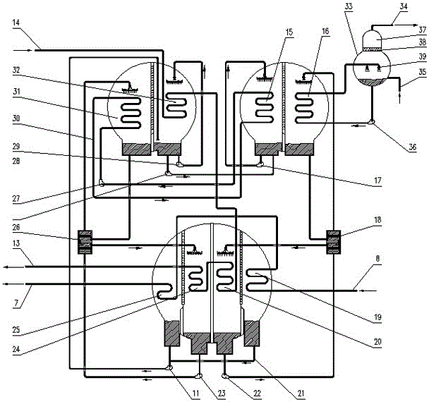
Fig. 2 is a flow chart of the operation of the large temperature rise two-stage type second-class lithium bromide absorption heat pump steam unit.
In the figure: an evaporator 1, an absorber 2, a hot water inlet 3, a hot water outlet 4, an evaporator refrigerant circulating pump 5, a solution heat exchanger 6, a cooling water outlet 7, a cooling water inlet 8, a condenser 9, a generator 10, a condenser refrigerant pump 11, a solution pump 12, a residual heat water outlet 13, a residual heat water inlet 14, a high-temperature evaporator 15, a high-temperature absorber 16, a high-temperature refrigerant circulating pump 17, a high-temperature solution heat exchanger 18, a high-temperature condenser 19, a high-temperature generator 20, a high-low temperature condenser water communicating pipeline 21, a high-temperature solution pump 22, a low-temperature solution pump 23, a low-temperature generator 24, a low-temperature condenser 25, a low-temperature solution heat exchanger 26, an internal circulation hot water pump 27, a refrigerant lift pump 28, a low-temperature refrigerant circulating pump 29, internal circulation hot water 30, a low-temperature absorber 31, a low-temperature evaporator 32, a vapor-liquid separator 33, a steam outlet 34, a make-up water inlet 35, a high-temperature hot water pump 36, a steam drum 37, A liquid baffle plate group 38 and a uniform distribution pipe 39.
Detailed Description
Referring to fig. 2, the invention relates to a large temperature rise two-stage type second lithium bromide absorption heat pump steam unit, which comprises a gas-liquid separator 33, a high-temperature hot water pump 36, a high-temperature evaporator 15, a high-temperature absorber 16, a high-temperature generator 20, a high-temperature condenser 19, a high-temperature solution heat exchanger 18, a low-temperature evaporator 32, a low-temperature absorber 31, a low-temperature generator 24, a low-temperature condenser 25, a low-temperature solution heat exchanger 26, a high-temperature solution pump 22, a high-temperature refrigerant circulating pump 17, a low-temperature solution pump 23, a low-temperature refrigerant circulating pump 29, a condenser refrigerant pump 11, a refrigerant lift pump 28, an internal circulation hot water pump 27, and pipelines, valves and a control system for connecting all the components. The method is characterized in that: a single-effect second-class heat pump high-temperature side solution circulation flow path is formed by a high-temperature evaporator 15, a high-temperature absorber 16, a high-temperature generator 20, a high-temperature condenser 19, a high-temperature solution heat exchanger 18, a high-temperature solution pump 22, a high-temperature refrigerant circulating pump 17 and the like; a low-temperature evaporator 32, a low-temperature absorber 31, a low-temperature generator 24, a low-temperature condenser 25, a low-temperature solution heat exchanger 26, a low-temperature solution pump 23, a low-temperature refrigerant circulating pump 29 and the like form a single-effect two-type heat pump low-temperature side solution circulating flow; the refrigerant water condensed by the high-temperature condenser 19 and the low-temperature condenser 25 is converged together through a refrigerant water communication pipeline 21 of the high-temperature condenser and the low-temperature condenser, and the condenser refrigerant pump 11 pumps all the refrigerant water into a liquid bag of the low-temperature evaporator 32, wherein one part of the refrigerant water is evaporated by the low-temperature evaporator 32, and the other part of the refrigerant water is pumped into a liquid bag of the high-temperature evaporator 15 by the refrigerant lifting pump 28 and evaporated by the high-temperature evaporator 15; the high-temperature side solution circulation flow and the low-temperature side solution circulation flow are relatively independent and are mutually related.
The waste heat water of the external system is connected in series, firstly enters the low-temperature evaporator 32 for cooling, then enters the high-temperature generator 15 for cooling, and finally enters the low-temperature generator 24 for cooling; the cooling water enters the high-temperature condenser 19 and then enters the low-temperature condenser 25 in series to take away heat; the internal circulation hot water 30 is pressurized by the internal circulation hot water pump 27, enters the low-temperature absorber 31 to be heated, and then enters the high-temperature evaporator 15 to be cooled, so that an internal circulation hot water system is formed. The water charging system continuously charges water into the vapor-liquid separator 33 or the high-temperature absorber 16, high-temperature hot water from the vapor-liquid separator is pumped into the high-temperature absorber 16 by the high-temperature hot water pump 36, a heated vapor-liquid two-phase mixture enters the vapor-liquid separator 33, and high-grade steam 34 is separated for users to use.
The high-temperature evaporator (15) and the high-temperature absorber (16) are arranged in a first cylinder with the highest pressure, the low-temperature evaporator (32) and the low-temperature absorber (31) are arranged in a second cylinder with the higher pressure, the high-temperature generator (20), the high-temperature condenser (19), the low-temperature generator (24) and the low-temperature condenser (25) are arranged in a third cylinder, the third cylinder is provided with two cavities, the high-temperature generator (20) and the high-temperature condenser (19) are arranged in the same cavity with the lowest pressure, the low-temperature generator (24) and the low-temperature condenser (25) are arranged in the other cavity with the lower pressure, the first cylinder and the second cylinder are arranged in parallel at the upper part, and the third cylinder is arranged at the lower part; the gas-liquid separator (33) is placed at the upper part of the outer side of the high-temperature absorber (16) or at the top of the unit.
A vapor-liquid separation uniform distribution pipe 39 is arranged in the middle vapor phase region in the barrel body of the vapor-liquid separator 33, and a baffle plate is arranged below the uniform distribution pipe 39; the upper part of the cylinder body is provided with a steam pocket 37, the steam pocket 37 is internally provided with a horizontally-placed three-folding herringbone liquid baffle group 38 which only can pass steam, and the moisture content of the output saturated steam is ensured to be less than 3 percent.
The steam-liquid separating space is arranged on the upper part of the steam-liquid outlet pipe box of the high-temperature absorber 16, which is higher than the pipe distribution area, so that the inlet of the heat transfer pipe at one end of the water inlet pipe box of the high-temperature absorber 16 can be completely filled with liquid, the heat transfer area of the high-temperature absorber 16 is fully utilized, and the heat exchange performance of two-phase flow in the heat transfer pipe is improved.
The solution circulation process at the high temperature side of the single-effect second-class heat pump is as follows: the dilute solution at the bottom of the high-temperature absorber 16 is cooled by the power of pressure difference and potential difference in the upper and lower cylinders through the high-temperature solution heat exchanger 18 and automatically flows into the high-temperature generator 20 to be concentrated into a concentrated solution, the generated refrigerant steam is condensed into refrigerant water by the high-temperature condenser 19, the concentrated solution in the liquid bag of the high-temperature generator is lifted by the high-temperature solution pump 22, is heated by the high-temperature solution heat exchanger 18 and enters the high-temperature absorber 16 for spraying, and the high-temperature refrigerant steam evaporated from the high-temperature evaporator 15 is absorbed to be changed into the dilute solution; the high-temperature refrigerant circulating pump 17 pumps the refrigerant water in the liquid bag of the high-temperature evaporator 15 into the high-temperature evaporator spraying plate, the refrigerant water is uniformly sprayed to the surface of the heat transfer pipe of the high-temperature evaporator to absorb heat and is evaporated into high-temperature refrigerant steam, and the circulation is continuously carried out.
The low-temperature side solution circulation process of the single-effect second-class heat pump comprises the following steps: the dilute solution at the bottom of the low-temperature absorber 31 is cooled by the power of the pressure difference and the potential difference of the upper cylinder and the lower cylinder through the low-temperature solution heat exchanger 26 and automatically flows into the low-temperature generator 24 to be concentrated into a concentrated solution, the generated refrigerant steam is condensed into refrigerant water by the low-temperature condenser 25, the concentrated solution in the liquid bag of the low-temperature generator is lifted by the low-temperature solution pump 23, is heated by the low-temperature solution heat exchanger 26 and enters the low-temperature absorber 31 to be sprayed, and the high-temperature refrigerant steam evaporated from the low-temperature evaporator 32 is absorbed to be changed into the dilute solution; the low-temperature refrigerant circulating pump 29 pumps the refrigerant water in the liquid bag of the low-temperature evaporator 32 into the low-temperature evaporator shower plate, uniformly showers the refrigerant water to the surface of the heat transfer pipe of the low-temperature evaporator to absorb heat and evaporate the refrigerant water into high-temperature refrigerant steam, and the circulation is continued.
In addition to the above embodiments, the present invention also includes other embodiments, and any technical solutions formed by equivalent transformation or equivalent replacement should fall within the scope of the claims of the present invention.