CN113562880A - Garbage penetrating fluid wastewater treatment equipment and treatment process - Google Patents
Garbage penetrating fluid wastewater treatment equipment and treatment process Download PDFInfo
- Publication number
- CN113562880A CN113562880A CN202110938066.5A CN202110938066A CN113562880A CN 113562880 A CN113562880 A CN 113562880A CN 202110938066 A CN202110938066 A CN 202110938066A CN 113562880 A CN113562880 A CN 113562880A
- Authority
- CN
- China
- Prior art keywords
- wall
- treatment tank
- refuse
- pipe
- wastewater treatment
- Prior art date
- Legal status (The legal status is an assumption and is not a legal conclusion. Google has not performed a legal analysis and makes no representation as to the accuracy of the status listed.)
- Granted
Links
Images


Classifications
-
- C—CHEMISTRY; METALLURGY
- C02—TREATMENT OF WATER, WASTE WATER, SEWAGE, OR SLUDGE
- C02F—TREATMENT OF WATER, WASTE WATER, SEWAGE, OR SLUDGE
- C02F9/00—Multistage treatment of water, waste water or sewage
-
- A—HUMAN NECESSITIES
- A61—MEDICAL OR VETERINARY SCIENCE; HYGIENE
- A61L—METHODS OR APPARATUS FOR STERILISING MATERIALS OR OBJECTS IN GENERAL; DISINFECTION, STERILISATION OR DEODORISATION OF AIR; CHEMICAL ASPECTS OF BANDAGES, DRESSINGS, ABSORBENT PADS OR SURGICAL ARTICLES; MATERIALS FOR BANDAGES, DRESSINGS, ABSORBENT PADS OR SURGICAL ARTICLES
- A61L2/00—Methods or apparatus for disinfecting or sterilising materials or objects other than foodstuffs or contact lenses; Accessories therefor
- A61L2/16—Methods or apparatus for disinfecting or sterilising materials or objects other than foodstuffs or contact lenses; Accessories therefor using chemical substances
- A61L2/18—Liquid substances or solutions comprising solids or dissolved gases
-
- C—CHEMISTRY; METALLURGY
- C02—TREATMENT OF WATER, WASTE WATER, SEWAGE, OR SLUDGE
- C02F—TREATMENT OF WATER, WASTE WATER, SEWAGE, OR SLUDGE
- C02F1/00—Treatment of water, waste water, or sewage
- C02F1/001—Processes for the treatment of water whereby the filtration technique is of importance
-
- C—CHEMISTRY; METALLURGY
- C02—TREATMENT OF WATER, WASTE WATER, SEWAGE, OR SLUDGE
- C02F—TREATMENT OF WATER, WASTE WATER, SEWAGE, OR SLUDGE
- C02F1/00—Treatment of water, waste water, or sewage
- C02F1/50—Treatment of water, waste water, or sewage by addition or application of a germicide or by oligodynamic treatment
-
- C—CHEMISTRY; METALLURGY
- C02—TREATMENT OF WATER, WASTE WATER, SEWAGE, OR SLUDGE
- C02F—TREATMENT OF WATER, WASTE WATER, SEWAGE, OR SLUDGE
- C02F1/00—Treatment of water, waste water, or sewage
- C02F1/52—Treatment of water, waste water, or sewage by flocculation or precipitation of suspended impurities
- C02F1/54—Treatment of water, waste water, or sewage by flocculation or precipitation of suspended impurities using organic material
- C02F1/56—Macromolecular compounds
-
- C—CHEMISTRY; METALLURGY
- C02—TREATMENT OF WATER, WASTE WATER, SEWAGE, OR SLUDGE
- C02F—TREATMENT OF WATER, WASTE WATER, SEWAGE, OR SLUDGE
- C02F1/00—Treatment of water, waste water, or sewage
- C02F1/72—Treatment of water, waste water, or sewage by oxidation
- C02F1/722—Oxidation by peroxides
-
- C—CHEMISTRY; METALLURGY
- C02—TREATMENT OF WATER, WASTE WATER, SEWAGE, OR SLUDGE
- C02F—TREATMENT OF WATER, WASTE WATER, SEWAGE, OR SLUDGE
- C02F2103/00—Nature of the water, waste water, sewage or sludge to be treated
- C02F2103/06—Contaminated groundwater or leachate
-
- C—CHEMISTRY; METALLURGY
- C02—TREATMENT OF WATER, WASTE WATER, SEWAGE, OR SLUDGE
- C02F—TREATMENT OF WATER, WASTE WATER, SEWAGE, OR SLUDGE
- C02F2301/00—General aspects of water treatment
- C02F2301/08—Multistage treatments, e.g. repetition of the same process step under different conditions
-
- C—CHEMISTRY; METALLURGY
- C02—TREATMENT OF WATER, WASTE WATER, SEWAGE, OR SLUDGE
- C02F—TREATMENT OF WATER, WASTE WATER, SEWAGE, OR SLUDGE
- C02F2303/00—Specific treatment goals
- C02F2303/04—Disinfection
-
- C—CHEMISTRY; METALLURGY
- C02—TREATMENT OF WATER, WASTE WATER, SEWAGE, OR SLUDGE
- C02F—TREATMENT OF WATER, WASTE WATER, SEWAGE, OR SLUDGE
- C02F2303/00—Specific treatment goals
- C02F2303/14—Maintenance of water treatment installations
-
- Y—GENERAL TAGGING OF NEW TECHNOLOGICAL DEVELOPMENTS; GENERAL TAGGING OF CROSS-SECTIONAL TECHNOLOGIES SPANNING OVER SEVERAL SECTIONS OF THE IPC; TECHNICAL SUBJECTS COVERED BY FORMER USPC CROSS-REFERENCE ART COLLECTIONS [XRACs] AND DIGESTS
- Y02—TECHNOLOGIES OR APPLICATIONS FOR MITIGATION OR ADAPTATION AGAINST CLIMATE CHANGE
- Y02W—CLIMATE CHANGE MITIGATION TECHNOLOGIES RELATED TO WASTEWATER TREATMENT OR WASTE MANAGEMENT
- Y02W10/00—Technologies for wastewater treatment
- Y02W10/30—Wastewater or sewage treatment systems using renewable energies
- Y02W10/37—Wastewater or sewage treatment systems using renewable energies using solar energy
Abstract
The invention discloses garbage penetrating fluid wastewater treatment equipment and a treatment process, which comprise a treatment tank, a support plate and a second treatment tank, wherein the second treatment tank is arranged at the top of the support plate, an air purification pipe is arranged at the top of the second treatment tank, a first tank is arranged on the back surface of the treatment tank, a killing tank is arranged at the top of the treatment tank, a cleaning tank is arranged at the top of the support plate, the first treatment tank is arranged at the top of the support plate, and a trigger is arranged on the bottom wall of the interior of the second treatment tank. The air purification device can purify air by installing the air purification pipe, malodorous gas generated by percolate is discharged from the air purification pipe, the fan drives the air to flow, then the malodorous gas enters the interior of the fragrance tank through the pipeline, the heating wire heats the fragrance, so that the malodorous gas is mixed with the fragrance, the malodorous gas is diluted, and the air purification function is realized.
Description
Technical Field
The invention relates to the technical field of garbage treatment, in particular to garbage penetrating fluid wastewater treatment equipment and a garbage penetrating fluid wastewater treatment process.
Background
The landfill leachate is high-concentration organic wastewater which is formed by deducting saturated water holding capacity of garbage and a soil covering layer from water contained in the garbage in a garbage landfill, rain, snow water entering the landfill and other water, and passing through the garbage layer and the soil covering layer, the landfill leachate is extremely harmful, a large amount of leachate can be generated in the garbage landfill, heavy metals in the leachate seriously exceed the standard, and the surrounding soil can be seriously polluted.
The existing garbage penetrating fluid wastewater treatment equipment has the defects that:
1. the comparison document CN105621767A discloses a processing apparatus of rubbish penetrant reverse osmosis concentration, the right item of protection "includes material conveyor, material conveyor connects the pre-heater, washing liquid storage tank and degasser are connected to the pre-heater, the washing liquid storage tank is connected with the pre-heater through washing circulating pump and diverter valve one, the other end of pre-heater loops through diverter valve ten, drain pump one and condensate water jar one are connected catch water, catch water is connected with the degasser, the heater is connected with catch water, the heater is connected with steam compressor and ooff valve, steam compressor connects the separation chamber, and the separation chamber is connected with the heater, ooff valve connects the drying chamber, the drying chamber is connected with vacuum pump and condensate water jar two that parallelly connected through the condenser, condensate water jar two is connected with drain pump two. The invention has the beneficial effects that: the problems that an MVR evaporator is high in blocking frequency of treating garbage penetrating fluid, short in cleaning period and high in water content of concentrated solution are effectively solved, but a device of the MVR evaporator is short of a structure for purifying air, the surrounding environment is seriously affected by stink emitted by the penetrating fluid, and the air needs to be purified;
2. the reference CN111439828A discloses a kitchen waste penetrant sewage treatment system, and the protection right "solves the technical problem of poor effect of kitchen waste penetrant sewage treatment in the prior art. This system includes the reaction tank and is located biological rotating disk subassembly in the reaction tank, wherein, the reaction tank is closed structure, biological rotating disk subassembly includes a plurality of disk bodies and is located every the aeration pipe of disk body front and back side, wherein, a plurality of be equipped with the biomembrane of constituteing by anti-adversity fungus crowd on the disk body, the aeration pipe can be for anti-adversity fungus crowd on the biomembrane provides oxygen so that dissolved oxygen volume in the reaction tank reaches the required dissolved oxygen volume of anti-adversity fungus crowd on the biomembrane. The stress-resistant flora of the kitchen waste penetrant sewage keeps better activity all the time in the treatment process, and the removal rate of BOD, COD and T-N, T-P, SS reaches more than 90 percent, so that the treatment effect of the kitchen waste penetrant is improved, but the device is lack of cleaning equipment, and the added chemical reagents required by the treatment of the percolate each time are different in proportion and need to be added after being cleaned;
3. the reference document CN107720990A discloses a rubbish penetrant and municipal sewage treatment plant, and the right item of protection "includes disinfection and sterilization groove, heavy metal separating tank, secondary reaction tank and precipitation tank, all be equipped with the stirring rake in disinfection and sterilization groove, heavy metal separating tank and the secondary reaction tank, the stirring rake passes through the motor drive of top, disinfection and sterilization groove, heavy metal separating tank and secondary reaction tank outside are equipped with first stock solution bucket, second stock solution bucket and third stock solution bucket respectively, be equipped with the stirring rake in the second stock solution bucket, the top is equipped with agitator motor, the disinfection and sterilization groove front end blows off the tower through being connected with ammonia nitrogen, ammonia nitrogen blows off the tower top and is equipped with the water inlet, and the below is equipped with the delivery port, the delivery port passes through pipe connection to disinfection and sterilization groove. The filter and decomposition of organic matters, nitrogen, phosphorus and heavy metals can reach an efficient and stable treatment and reach the discharge standard, but the device is lack of a sterilization structure, the leachate contains a large amount of bacteria, workers are easily damaged by the bacteria, and the leachate needs to be sterilized;
4. the reference document CN202543003U discloses a refuse leachate treatment device, the right item of protection "relates to a treatment device of waste water, this treatment device is including the membrane biological reaction system and the dish tubular reverse osmosis system that connect gradually, the membrane biological reaction system includes the bioreactor that connects gradually through the pipeline, the circulating pump, the biomembrane post spare, still be connected with the backflow pipeline that flows the concentrate after the biomembrane post spare filters back to the bioreactor between biomembrane post spare and the bioreactor, the dish tubular reverse osmosis system includes the former water pitcher that connects gradually through the pipeline, the former water pump, the sand filtration booster pump, the sand filter, the cartridge filter, high pressure plunger pump, reverse osmosis membrane post system, former water pitcher one side is equipped with the acid storage tank, be equipped with the acidification pump between the pipeline of acid storage tank and former water pitcher, the utility model discloses can combine MBR and DTRO two kinds of treatment modes to handle rubbish leachate, the treatment device of water, The on-site treatment of the garbage penetrating fluid can be realized, the removal capability of ammonia nitrogen and organic matters is improved, and the treated effluent can stably reach the national first-level discharge standard, but the device lacks an energy-saving structure, and needs to be closed when not working, so that the service life of the device is prevented from being shortened when the device works for a long time.
Disclosure of Invention
The invention aims to provide garbage penetrating fluid wastewater treatment equipment and a treatment process, and aims to solve the problems of lack of an air purification device, a cleaning structure, a killing structure and an energy-saving mechanism in the background art.
In order to achieve the purpose, the invention provides the following technical scheme: a garbage penetrating fluid wastewater treatment device and a treatment process comprise a treatment tank, a support plate and a second treatment tank, wherein the support plate is installed on the outer wall of the treatment tank, the second treatment tank is installed at the top of the support plate, and an air purification pipe is installed at the top of the second treatment tank;
the inner wall of the air purification pipe is provided with a fan, the inner wall of the air purification pipe is provided with a fragrance groove, volatile fragrance is filled in the fragrance groove, the bottom wall of the inner part of the fragrance groove is provided with an electric heating wire, the fragrance groove is connected with the fan through a pipeline, and the top of the air purification pipe is provided with an exhaust hole;
the back mounted who handles the pond has a case, the top of handling the pond is installed and is killed the pond, the top of backup pad is installed and is washd the case, and washs the case and be located one side of No. two processing jars, No. one processing jar is installed at the top of backup pad, and No. one processing jar is located the front of No. two processing jars, and sealed window is all installed with the outer wall of No. two processing jars to a processing jar, No. two the inside diapire of processing jar install the trigger.
Preferably, wash the inner wall of case and install first electric telescopic handle, the fixed plate is installed to first electric telescopic handle's one end, and the scavenge pipe is installed to the outer wall of fixed plate, and the one end of scavenge pipe extends the outer wall of wasing the case, and rotatory nozzle is installed through the bearing to the one end of scavenge pipe, and flexible pipe is installed to the outer wall of fixed plate, and the one end of flexible pipe extends the outer wall of wasing the case, and the one end of flexible pipe is connected with the one end of scavenge pipe, and the injection pipe of a plurality of L types is installed to rotatory nozzle's outer wall.
Preferably, the disinfection chamber is installed to the inner wall in the pond of killing, and the inside packing in disinfection chamber has the antiseptic solution, and the water pump is installed to the inside diapire in the pond of killing, and the inlet tube is installed to the input of a water pump, and the one end of inlet tube extends into the inside in disinfection chamber, and the outlet pipe is installed to the output of a water pump, and the shunt is installed to the one end of outlet pipe, and a plurality of solenoid valves are installed to the inner wall of shunt, and a plurality of pipes of killing are installed to the outer wall of shunt, and the one end of the pipe of killing all extends into the inside of a treatment tank and No. two treatment tanks, and the one end of the pipe of killing is connected with the one end of flexible pipe.
Preferably, two sets of fixed blocks are installed to the inside diapire of trigger, and the outer wall of fixed block runs through and installs the cable, and the outer wall of cable encircles and installs a spring, and two sets of limiting plates are installed to the inside roof of trigger, and the inside roof of trigger runs through and installs the lift post, and the lift post is located between two sets of limiting plates, and the top of lift post is connected with the floater through the cable.
Preferably, the filter screen is installed No. one to the inner wall of handling the pond, handles the front in pond and installs the discharge hole, and the movable rod is installed to the inside roof of discharge hole, and spacing spring is installed to the outer wall of movable rod, and the one end of spacing spring is connected with the inside roof of discharge hole, handles the inner wall in pond and installs second electric telescopic handle, and second electric telescopic handle is located the top of filter screen No. one, and the board of cleaing away of L type is installed to second electric telescopic handle's one end.
Preferably, No. two water pumps are installed to the inner wall of a case, and the inlet tube is installed to the input of No. two water pumps, and the one end of inlet tube extends into the inside of handling the pond, and the outlet pipe is installed to the output of No. two water pumps, and the one end of outlet pipe extends into the inside of handling the jar No. one.
Preferably, the buckler is installed to the inside diapire of a treatment tank, agitator motor is installed to the inner wall of buckler, and agitator motor's output extends the top of buckler, agitator motor's output is encircleed and is installed the stirring leaf, the third electric telescopic handle is installed to the inside diapire of a treatment tank, and the third electric telescopic handle is located one side of buckler, two sets of spouts are installed in the inner wall of a treatment tank is crisscross, No. two filter screens of slope are installed to the outer wall of spout, the discharge gate is installed to the outer wall of a treatment tank, disinfection shower nozzle is installed to the inside roof of a treatment tank, and disinfection shower nozzle is connected with the one end of killing the pipe.
Preferably, No. two inside roof of processing jar are installed and are eliminated and kill the shower nozzle, and eliminate and kill the shower nozzle and be connected with the one end of eliminating and killing the pipe, No. three filter screens are installed to the inner wall of No. two processing jars, the collecting box is installed to the outer wall of No. two processing jars, the protecting crust is installed to the inner wall of No. two processing jars, and the protecting crust is located the top of No. three filter screens, the inner wall of protecting crust is installed and is cleaned the motor, and the output that cleans the motor extends the outer wall of protecting crust, clean the output of motor and install reciprocal lead screw, the outer wall cover of reciprocal lead screw is equipped with the movable block, that is equipped with the brush in the bottom of movable block.
Preferably, the working steps of the device are as follows:
s1, firstly, enabling percolate to enter a treatment pool, filtering silt in the percolate by a first filter screen, performing primary filtration, starting a second electric telescopic rod, extending the second electric telescopic rod to drive a clearing plate to move, clearing silt accumulated on the first filter screen by the clearing plate, pushing the silt to move towards the direction of a discharge hole by the clearing plate, extruding a movable rod by the silt, extending a limiting spring, and then discharging the silt out of the treatment pool to realize the function of primary filtration;
s2, before leachate is treated, starting a first water pump, driving disinfectant to flow to a first treatment tank and a second treatment tank by the first water pump, opening a sealing window, starting a first electric telescopic rod, driving a fixing plate to extend by the first electric telescopic rod, driving a rotary spray head to enter the first treatment tank and the second treatment tank by the fixing plate, extending a telescopic pipe, spraying the disinfectant from a spraying pipe, and rotationally spraying the rotary spray head in the first treatment tank and the second treatment tank due to reaction force during spraying, so that the function of disinfecting the interiors of the first treatment tank and the second treatment tank is realized, and bacteria are prevented from breeding;
s3, starting a second water pump, conveying the primarily filtered percolate to the inside of a first treatment tank by the second water pump, adding a flocculating agent into the inside of the first treatment tank, starting a stirring motor, driving a stirring blade to rotate by the stirring motor, stirring the percolate by the stirring blade, fully mixing the percolate and the flocculating agent, adsorbing tiny impurities in the percolate by the flocculating agent, filtering the percolate for the second time, enlarging the adsorbed flocculating agent and intercepting the adsorbed flocculating agent by a second filter screen, starting a third electric telescopic rod, driving the second filter screen to slide in a sliding groove by the third electric telescopic rod, and sliding a flocculating agent block object accumulated at the top of the second filter screen out of the first treatment tank after reaching a discharge port;
s4, conveying the percolate in the first treatment tank to the second treatment tank through a water pump, adding a compound Fenton reagent, hydrogen peroxide, compound alkali, lime, PAM and other purification liquids into the second treatment tank, waiting for a percolate reaction, generating precipitates along with the reaction, starting a cleaning motor, driving a reciprocating lead screw to rotate by the cleaning motor, driving a moving block to move by the reciprocating lead screw, and driving a hairbrush to clean the precipitates into a collection box by the moving block;
s5, the malodorous gas generated by the percolate is discharged from the air purification pipe, the fan drives the air to flow, then the malodorous gas enters the interior of the fragrance tank through the pipeline, the heating wire is started, and the heating wire heats the fragrance, so that the malodorous gas is mixed with the fragrance, the malodorous gas is diluted, and the air purification function is realized.
Compared with the prior art, the invention has the beneficial effects that:
1. the air purification device can purify air by installing the air purification pipe, malodorous gas generated by percolate is discharged from the air purification pipe, the fan drives the air to flow, then the malodorous gas enters the interior of the fragrance tank through the pipeline, the heating wire heats the fragrance, so that the malodorous gas is mixed with the fragrance, the malodorous gas is diluted, and the air purification function is realized;
2. the first treatment tank and the second treatment tank can be cleaned by the aid of the cleaning box, before leachate is treated, the first water pump drives disinfectant to flow to the first treatment tank and the second treatment tank, the sealing window is opened, the first electric telescopic rod drives the fixing plate to extend, the fixing plate drives the rotary spray head to enter the first treatment tank and the second treatment tank, the telescopic pipe extends, and then the disinfectant is sprayed out of the spray pipe;
3. the disinfection device can disinfect and sterilize the interior of the device by installing the disinfection pool, the first water pump can convey disinfectant to each part so as to be convenient for disinfection, the shunt can conveniently shunt the disinfectant, and the electromagnetic valve can control the opening and closing of each disinfection pipe;
4. the energy waste can be reduced by installing the trigger, when the second treatment tank contains percolate, the floating ball rises, the floating ball drives the lifting column to rise, the first spring extends to drive the two cables to be in contact, the circuit is communicated, so that the second treatment tank starts to work, when no percolate exists, the lifting column descends, the cables are separated, the circuit is disconnected, the trigger type work can be realized, the device cannot be opened for a long time, and the energy and the power are greatly saved.
Drawings
FIG. 1 is a schematic view of the external structure of the present invention;
FIG. 2 is a schematic view of the air purification tube structure of the present invention;
FIG. 3 is a schematic view showing a part of the structure of a treatment tank according to the present invention;
FIG. 4 is a schematic view of the first treatment tank of the present invention;
FIG. 5 is a schematic view of the second treatment tank of the present invention;
FIG. 6 is a schematic diagram of a flip-flop according to the present invention;
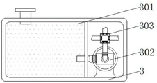
FIG. 7 is a schematic view of a portion of the disinfection tank of the present invention;
FIG. 8 is a schematic view showing a part of the structure of the cleaning tank of the present invention;
fig. 9 is a schematic view of a partial structure of the rotary nozzle head of the present invention.
In the figure: 1. a treatment tank; 101. a first filter screen; 102. a limiting spring; 103. a movable rod; 104. a second electric telescopic rod; 105. removing the plate; 106. a discharge hole; 2. a first box; 201. a second water pump; 3. a sterilizing pool; 301. a disinfection chamber; 302. a water pump I; 303. a flow divider; 4. a support plate; 401. a first treatment tank; 402. a waterproof shell; 403. a stirring motor; 404. a third electric telescopic rod; 405. a chute; 406. a second filter screen; 407. a discharge port; 408. a disinfection nozzle; 5. a second treatment tank; 501. sterilizing the spray head; 502. a third filter screen; 503. a collection box; 504. a protective shell; 505. cleaning a motor; 506. a reciprocating screw rod; 6. an air purification pipe; 601. a fan; 602. a fragrance groove; 603. an electric heating wire; 604. an exhaust hole; 7. a cleaning tank; 701. a first electric telescopic rod; 702. a fixing plate; 703. rotating the spray head; 704. an injection pipe; 705. a telescopic pipe; 8. a trigger; 801. a cable; 802. a first spring; 803. a limiting plate; 804. a lifting column; 805. a floating ball; 9. and (5) sealing the window.
Detailed Description
The technical solutions in the embodiments of the present invention will be clearly and completely described below with reference to the drawings in the embodiments of the present invention, and it is obvious that the described embodiments are only a part of the embodiments of the present invention, and not all of the embodiments. All other embodiments, which can be derived by a person skilled in the art from the embodiments given herein without making any creative effort, shall fall within the protection scope of the present invention.
In the description of the present invention, it should be noted that the terms "upper", "lower", "inner", "outer", "front", "rear", "both ends", "one end", "the other end", and the like indicate orientations or positional relationships based on those shown in the drawings, and are only for convenience of description and simplicity of description, but do not indicate or imply that the referred device or element must have a specific orientation, be constructed in a specific orientation, and be operated, and thus, should not be construed as limiting the present invention. Furthermore, the terms "first" and "second" are used for descriptive purposes only and are not to be construed as indicating or implying relative importance.
In the description of the present invention, it is to be noted that, unless otherwise explicitly specified or limited, the terms "mounted," "disposed," "connected," and the like are to be construed broadly, such as "connected," which may be fixedly connected, detachably connected, or integrally connected; can be mechanically or electrically connected; they may be connected directly or indirectly through intervening media, or they may be interconnected between two elements. The specific meanings of the above terms in the present invention can be understood in specific cases to those skilled in the art.
Example 1: referring to fig. 1, an embodiment of the present invention: a garbage penetrating fluid wastewater treatment device and a treatment process comprise a treatment pool 1, a support plate 4 and a second treatment tank 5, wherein the support plate 4 is installed on the outer wall of the treatment pool 1, the second treatment tank 5 is installed on the top of the support plate 4, an air purification pipe 6 is installed on the top of the second treatment tank 5, a first tank 2 is installed on the back surface of the treatment pool 1, a killing pool 3 is installed on the top of the treatment pool 1, a cleaning tank 7 is installed on the top of the support plate 4, the cleaning tank 7 is located on one side of the second treatment tank 5, a first treatment tank 401 is installed on the top of the support plate 4, the first treatment tank 401 is located on the front surface of the second treatment tank 5, sealing windows 9 are installed on the outer walls of the first treatment tank 401 and the second treatment tank 5, a trigger 8 is installed on the inner bottom wall of the second treatment tank 5, the treatment pool 1 can preliminarily filter a penetrating fluid, the first tank 2 can protect an inner second water pump 201, the sterilizing tank 3 can store disinfectant, the supporting plate 4 can support the first treatment tank 401 and the second treatment tank 5 at the top, the first treatment tank 401 can remove impurities in percolate, the second treatment tank 5 can purify the percolate, the air purifying pipe 6 can purify air, the cleaning box 7 can clean the interiors of the first treatment tank 401 and the second treatment tank 5, the trigger 8 can facilitate the device to save energy, and the sealing window 9 can be opened and closed to facilitate cleaning;
example 2: referring to fig. 2, an embodiment of the present invention: a fan 601 is installed on the inner wall of an air purification pipe 6, a fragrance groove 602 is installed on the inner wall of the air purification pipe 6, volatile fragrance is filled in the fragrance groove 602, an electric heating wire 603 is installed on the bottom wall of the fragrance groove 602, the fragrance groove 602 is connected with the fan 601 through a pipeline, an exhaust hole 604 is formed in the top of the air purification pipe 6, malodorous gas generated by percolate is exhausted from the air purification pipe 6, the fan 601 drives air to flow, then the malodorous gas enters the fragrance groove 602 through the pipeline, the electric heating wire 603 is started, and the electric heating wire 603 heats the fragrance, so that the malodorous gas and the fragrance are mixed, the malodorous gas is diluted, and the air purification function is realized.
Example 3: referring to fig. 8 and 9, an embodiment of the present invention: a garbage penetrating fluid wastewater treatment device and a treatment process are disclosed, wherein a first electric telescopic rod 701 is installed on the inner wall of a cleaning tank 7, a fixed plate 702 is installed at one end of the first electric telescopic rod 701, a cleaning pipe is installed on the outer wall of the fixed plate 702, one end of the cleaning pipe extends out of the outer wall of the cleaning tank 7, a rotary spray nozzle 703 is installed at one end of the cleaning pipe through a bearing, an extension pipe 705 is installed on the outer wall of the fixed plate 702, one end of the extension pipe 705 extends out of the outer wall of the cleaning tank 7, one end of the extension pipe 705 is connected with one end of the cleaning pipe, a plurality of L-shaped spray pipes 704 are installed on the outer wall of the rotary spray nozzle 703, before leachate begins to be treated, a first water pump 302 is started, the first water pump 302 drives disinfectant to flow to a first treatment tank 401 and a second treatment tank 5, a sealing window 9 is opened, the first electric telescopic rod 701 is started, the first electric telescopic rod 701 drives the fixed plate 702 to extend, fixed plate 702 drives rotatory nozzle 703 and enters into the inside of a processing jar 401 and No. two processing jars 5, and flexible pipe 705 extends, and the antiseptic solution is spout from injection pipe 704 afterwards, because there is reaction force during the blowout, rotatory nozzle 703 sprays in the inside rotation of a processing jar 401 and No. two processing jars 5, realizes carrying out sterile function to the inside of a processing jar 401 and No. two processing jars 5, prevents bacterial growing.
Example 4: referring to fig. 7, an embodiment of the present invention: a garbage penetrating fluid wastewater treatment device and a treatment process are disclosed, wherein a disinfection cavity 301 is arranged on the inner wall of a disinfection tank 3, disinfectant is filled in the disinfection cavity 301, a first water pump 302 is arranged on the bottom wall of the disinfection tank 3, a water inlet pipe is arranged at the input end of the first water pump 302, one end of the water inlet pipe extends into the disinfection cavity 301, the output end of the first water pump 302 is provided with a water outlet pipe, and one end of the water outlet pipe is provided with a diverter 303, the inner wall of the diverter 303 is provided with a plurality of electromagnetic valves, the outer wall of the diverter 303 is provided with a plurality of killing pipes, one end of the sterilizing pipe extends into the first processing tank 401 and the second processing tank 5, one end of the sterilizing pipe is connected with one end of the telescopic pipe 705, the first water pump 302 can convey disinfectant to each part, so as to disinfect, shunt 303 can conveniently shunt the disinfectant, and the solenoid valve can control opening and closing of every pipe that disinfects.
Example 5: referring to fig. 6, an embodiment of the present invention: a garbage penetrating fluid waste water treatment device and a treatment process are disclosed, wherein two groups of fixed blocks are arranged on the inner bottom wall of a trigger 8, a cable 801 is arranged on the outer wall of each fixed block in a penetrating manner, a first spring 802 is arranged on the outer wall of the cable 801 in a surrounding manner, two groups of limiting plates 803 are arranged on the inner top wall of the trigger 8, a lifting column 804 is arranged on the inner top wall of the trigger 8 in a penetrating manner, the lifting column 804 is positioned between the two groups of limiting plates 803, the top of the lifting column 804 is connected with a floating ball 805 through a cable, when the second treatment tank 5 contains a penetrating fluid, the floating ball 805 rises, the floating ball 805 drives the lifting column 804 to rise, the first spring 802 extends to drive the two cables 801 to contact, the circuits are communicated, so that the second treatment tank 5 starts to work, when the penetrating fluid does not exist, the lifting column 804 descends to separate the cables 801, the circuits are disconnected, so that a trigger type work can be realized, and the device cannot be opened for a long time, greatly saving energy and electric power.
Example 6: referring to fig. 1, fig. 3, fig. 4 and fig. 5, an embodiment of the present invention: a garbage penetrating fluid wastewater treatment device and a treatment process are disclosed, wherein a first filter screen 101 is arranged on the inner wall of a treatment pool 1, a discharge hole 106 is arranged on the front surface of the treatment pool 1, a movable rod 103 is arranged on the inner top wall of the discharge hole 106, a limiting spring 102 is arranged on the outer wall of the movable rod 103, one end of the limiting spring 102 is connected with the inner top wall of the discharge hole 106, a second electric telescopic rod 104 is arranged on the inner wall of the treatment pool 1, the second electric telescopic rod 104 is positioned above the first filter screen 101, an L-shaped clearing plate 105 is arranged at one end of the second electric telescopic rod 104, a second water pump 201 is arranged on the inner wall of a first tank 2, a water inlet pipe is arranged at the input end of the second water pump 201, one end of the water inlet pipe extends into the treatment pool 1, a water outlet pipe is arranged at the output end of the second water pump 201, one end of the water outlet pipe extends into a first treatment tank 401, a waterproof shell 402 is arranged on the inner bottom wall of the first treatment tank 401, a stirring motor 403 is installed on the inner wall of a waterproof shell 402, the output end of the stirring motor 403 extends out of the top of the waterproof shell 402, stirring blades are installed around the output end of the stirring motor 403, a third electric telescopic rod 404 is installed on the bottom wall inside a first treatment tank 401, the third electric telescopic rod 404 is located on one side of the waterproof shell 402, two groups of sliding grooves 405 are installed on the inner wall of the first treatment tank 401 in a staggered mode, an inclined second filter screen 406 is installed on the outer wall of the sliding grooves 405, a discharge hole 407 is installed on the outer wall of the first treatment tank 401, a disinfection nozzle 408 is installed on the top wall inside the first treatment tank 401 and is connected with one end of a disinfection pipe 408, a garbage penetrating fluid wastewater treatment device and treatment process are provided, a disinfection nozzle 501 is installed on the top wall inside a second treatment tank 5 and is connected with one end of the disinfection pipe, a third filter screen 502 is installed on the inner wall of the second treatment tank 5, the collecting box 503 is installed on the outer wall of the second treatment tank 5, the protective shell 504 is installed on the inner wall of the second treatment tank 5, the protective shell 504 is located above the third filter screen 502, the cleaning motor 505 is installed on the inner wall of the protective shell 504, the output end of the cleaning motor 505 extends out of the outer wall of the protective shell 504, the reciprocating lead screw 506 is installed at the output end of the cleaning motor 505, the moving block is sleeved on the outer wall of the reciprocating lead screw 506, the bottom of the moving block is provided with a brush, firstly, the leachate enters the treatment pool 1, silt in the leachate is filtered by the first filter screen 101 for preliminary filtration, the second electric telescopic rod 104 is started, the second electric telescopic rod 104 extends to drive the cleaning plate 105 to move, the cleaning plate 105 cleans the silt accumulated on the first filter screen 101, the silt is pushed by the cleaning plate 105 to move towards the amount of the discharge hole 106, the movable rod 103 is extruded by the silt, and the limiting spring 102 extends, then the silt is discharged out of the treatment pool 1, the function of primary filtration is realized, before the leachate is treated, the first water pump 302 is started, the first water pump 302 drives the disinfectant to flow to the first treatment tank 401 and the second treatment tank 5, the sealing window 9 is opened, the first electric telescopic rod 701 is started, the first electric telescopic rod 701 drives the fixing plate 702 to extend, the fixing plate 702 drives the rotary spray head 703 to enter the interiors of the first treatment tank 401 and the second treatment tank 5, the telescopic pipe 705 extends, then the disinfectant is sprayed out from the spray pipe 704, due to the reactive force existing during spraying, the rotary spray head 703 rotates and sprays in the interiors of the first treatment tank 401 and the second treatment tank 5, the function of disinfecting the interiors of the first treatment tank 401 and the second treatment tank 5 is realized, the bacterial growth is prevented, the second water pump 201 is started, the second water pump 201 conveys the leachate after primary filtration to the interior of the first treatment tank 401, to the inside addition flocculating agent of a treatment tank 401, start agitator motor 403, agitator motor 403 drives the stirring leaf and rotates, the stirring leaf stirs filtration liquid, make intensive mixing between filtration liquid and the flocculating agent, the flocculating agent is with the small impurity adsorption in the filtration liquid, carry out secondary filter to filtration liquid, the flocculating agent adsorbs the back grow and is intercepted by No. two filter screens 406, start third electric telescopic handle 404, third electric telescopic handle 404 drives No. two filter screens 406 and slides in the inside of spout 405, reach behind discharge gate 407, No. two filter screens 406 top accumulational massive object slip out a treatment tank 401.
Further, the working steps of the device are as follows:
s1, firstly, the leachate enters a treatment pool 1, silt in the leachate is filtered by a first filter screen 101 for preliminary filtration, a second electric telescopic rod 104 is started, the second electric telescopic rod 104 extends to drive a clearing plate 105 to move, the clearing plate 105 clears away the silt accumulated on the first filter screen 101, the silt is pushed by the clearing plate 105 to move towards the volume of a discharge hole 106, the movable rod 103 is extruded by the silt, a limiting spring 102 extends, and then the silt is discharged out of the treatment pool 1, so that the preliminary filtration function is realized;
s2, before leachate begins to be treated, a first water pump 302 is started, the first water pump 302 drives disinfectant to flow into a first treatment tank 401 and a second treatment tank 5, a sealing window 9 is opened, a first electric telescopic rod 701 is started, the first electric telescopic rod 701 drives a fixing plate 702 to extend, the fixing plate 702 drives a rotary spray head 703 to enter the first treatment tank 401 and the second treatment tank 5, an extension pipe 705 extends, then the disinfectant is sprayed out of a spray pipe 704, and the rotary spray head 703 rotates and sprays in the first treatment tank 401 and the second treatment tank 5 due to the reaction force during spraying, so that the function of disinfecting the interiors of the first treatment tank 401 and the second treatment tank 5 is realized, and bacteria are prevented from breeding;
s3, starting a second water pump 201, conveying the primarily filtered percolate to the inside of a first treatment tank 401 by the second water pump 201, adding a flocculating agent into the inside of the first treatment tank 401, starting a stirring motor 403, driving stirring blades to rotate by the stirring motor 403, stirring the percolate by the stirring blades, fully mixing the percolate and the flocculating agent, adsorbing tiny impurities in the percolate by the flocculating agent, performing secondary filtration on the percolate, intercepting the adsorbed larger flocculate by a second filter screen 406, starting a third electric telescopic rod 404, driving the second filter screen 406 to slide in a chute 405 by the third electric telescopic rod 404, and after reaching a discharge port 407, sliding out of the first treatment tank 401 by a flocculating agent block object accumulated on the top of the second filter screen 406;
s4, conveying the percolate in the first treatment tank 401 to the inside of a second treatment tank 5 through a water pump, adding a compound Fenton reagent, hydrogen peroxide, compound alkali, lime, PAM and other purification solutions into the second treatment tank 5, waiting for percolate reaction, generating precipitates along with the reaction, starting a cleaning motor 505, driving a reciprocating screw rod 506 to rotate by the cleaning motor 505, driving a moving block to move by the reciprocating screw rod 506, and driving a brush to clean the precipitates into a collection box 503 by the moving block;
s5, malodorous gas generated by the percolate is discharged from the air purification pipe 6, the fan 601 drives the air to flow, then the malodorous gas enters the interior of the fragrance tank 602 through a pipeline, the heating wire 603 is started, and the heating wire 603 heats the fragrance, so that the malodorous gas is mixed with the fragrance, the malodorous gas is diluted, and the air purification function is realized.
The working principle is that firstly, leachate enters a treatment tank 1, silt in the leachate is filtered by a first filter screen 101, primary filtration is carried out, a second electric telescopic rod 104 is started, the second electric telescopic rod 104 extends to drive a clearing plate 105 to move, the clearing plate 105 clears away the silt accumulated on the first filter screen 101, the silt is pushed by the clearing plate 105 to move towards the direction of an exhaust hole 106, the silt extrudes a movable rod 103, a limiting spring 102 extends, then the silt is exhausted out of the treatment tank 1 to realize the function of the primary filtration, before the leachate is treated, a first water pump 302 is started, the first water pump 302 drives disinfectant to flow into a first treatment tank 401 and a second treatment tank 5, a sealed window 9 is opened, a first electric telescopic rod 701 is started, the first electric telescopic rod 701 drives a fixing plate 702 to extend, the fixing plate 702 drives a rotary spray nozzle 703 to enter the first treatment tank 401 and the second treatment tank 5, the extension pipe 705 extends, then disinfectant is sprayed out of the spray pipe 704, due to the reactive force existing during spraying, the rotary spray nozzle 703 is used for rotationally spraying in the first treatment tank 401 and the second treatment tank 5, the function of disinfecting the interiors of the first treatment tank 401 and the second treatment tank 5 is realized, bacteria are prevented from breeding, the second water pump 201 is started, the second water pump 201 conveys percolate after primary filtration to the interior of the first treatment tank 401, a flocculating agent is added into the interior of the first treatment tank 401, the stirring motor 403 is started, the stirring motor 403 drives the stirring blade to rotate, the stirring blade stirs the percolate, so that the percolate and the flocculating agent are fully mixed, the flocculating agent adsorbs micro impurities in the percolate, secondary filtration is performed on the percolate, the flocculating agent is enlarged and intercepted by the second filter screen 406 after adsorption, the third electric telescopic rod 404 is started, the third electric telescopic rod 404 drives the second filter screen 406 to slide in the chute 405, after the leachate reaches a discharge port 407, the flocculant block accumulated at the top of the second filter screen 406 slides out of the first treatment tank 401, the leachate in the first treatment tank 401 is conveyed to the inside of the second treatment tank 5 through a water pump, a compound fenton reagent, hydrogen peroxide, compound alkali, lime, PAM and other purification liquids are added into the second treatment tank 5, the leachate reaction is waited, precipitates are generated along with the reaction, a cleaning motor 505 is started, the cleaning motor 505 drives a reciprocating screw rod 506 to rotate, the reciprocating screw rod 506 drives a moving block to move, the moving block drives a brush to clean the precipitates into a collection box 503, malodorous gas generated by the leachate is discharged from an air purification pipe 6, a fan 601 drives air to flow, then the malodorous gas enters the inside of a fragrance tank 602 through a pipeline, an electric heating wire 603 is started, the fragrance is heated by an electric heating wire 603, and the malodorous gas and the fragrance are mixed, the malodorous gas is diluted, and the air purification function is realized.
It will be evident to those skilled in the art that the invention is not limited to the details of the foregoing illustrative embodiments, and that the present invention may be embodied in other specific forms without departing from the spirit or essential attributes thereof. The present embodiments are therefore to be considered in all respects as illustrative and not restrictive, the scope of the invention being indicated by the appended claims rather than by the foregoing description, and all changes which come within the meaning and range of equivalency of the claims are therefore intended to be embraced therein. Any reference sign in a claim should not be construed as limiting the claim concerned.
Claims (9)
1. The utility model provides a rubbish penetrant waste water treatment equips and processing technology, includes treatment tank (1), backup pad (4) and No. two treatment tank (5), its characterized in that: a supporting plate (4) is installed on the outer wall of the treatment pool (1), a second treatment tank (5) is installed on the top of the supporting plate (4), and an air purification pipe (6) is installed on the top of the second treatment tank (5);
a fan (601) is installed on the inner wall of the air purification pipe (6), a fragrance groove (602) is installed on the inner wall of the air purification pipe (6), volatile fragrance is filled in the fragrance groove (602), an electric heating wire (603) is installed on the bottom wall of the fragrance groove (602), the fragrance groove (602) is connected with the fan (601) through a pipeline, and an exhaust hole (604) is formed in the top of the air purification pipe (6);
the back mounted who handles pond (1) has case (2) No. one, the top of handling pond (1) is installed and is killed pond (3), the top of backup pad (4) is installed and is washd case (7), and washs case (7) and be located the one side of No. two processing jar (5), No. one processing jar (401) is installed at the top of backup pad (4), and just one processing jar (401) is located the front of No. two processing jar (5), and sealed window (9) are all installed with the outer wall of No. two processing jar (5) to one processing jar (401), trigger (8) are installed to the inside diapire of No. two processing jar (5).
2. The refuse permeate wastewater treatment equipment and the refuse permeate wastewater treatment process according to claim 1, wherein the refuse permeate wastewater treatment equipment comprises: the inner wall of wasing case (7) installs first electric telescopic handle (701), fixed plate (702) are installed to the one end of first electric telescopic handle (701), the scavenge pipe is installed to the outer wall of fixed plate (702), and the one end of scavenge pipe extends the outer wall of wasing case (7), rotatory nozzle (703) are installed through the bearing to the one end of scavenge pipe, flexible pipe (705) are installed to the outer wall of fixed plate (702), and the outer wall of wasing case (7) is extended to the one end of flexible pipe (705), the one end of flexible pipe (705) is connected with the one end of scavenge pipe, the injection pipe (704) of a plurality of L types are installed to the outer wall of rotatory nozzle (703).
3. The refuse permeate wastewater treatment equipment and the refuse permeate wastewater treatment process according to claim 1, wherein the refuse permeate wastewater treatment equipment comprises: disinfect chamber (301) are installed to the inner wall of killing pond (3), the inside packing of disinfect chamber (301) has the antiseptic solution, No. one water pump (302) are installed to the inside diapire of killing pond (3), the inlet tube is installed to the input of a water pump (302), and the one end of inlet tube extends into the inside of disinfect chamber (301), the outlet pipe is installed to the output of a water pump (302), and shunt (303) are installed to the one end of outlet pipe, a plurality of solenoid valves are installed to the inner wall of shunt (303), a plurality of pipes of killing are installed to the outer wall of shunt (303), and the one end of the pipe of killing all extends into the inside of a treatment tank (401) and No. two treatment tanks (5), the one end of the pipe of killing is connected with the one end of flexible pipe (705).
4. The refuse permeate wastewater treatment equipment and the refuse permeate wastewater treatment process according to claim 1, wherein the refuse permeate wastewater treatment equipment comprises: two sets of fixed blocks are installed to the inside diapire of trigger (8), and the outer wall of fixed block runs through and installs cable (801), and the outer wall of cable (801) encircles and installs spring (802) No. one, and two sets of limiting plate (803) are installed to the inside roof of trigger (8), and the inside roof of trigger (8) runs through and installs lift post (804), and lift post (804) are located between two sets of limiting plate (803), and the top of lift post (804) is connected with floater (805) through the cable.
5. The refuse permeate wastewater treatment equipment and the refuse permeate wastewater treatment process according to claim 1, wherein the refuse permeate wastewater treatment equipment comprises: a filter screen (101) is installed to the inner wall of handling pond (1), it installs discharge hole (106) to handle the front in pond (1), movable rod (103) are installed to the inside roof of discharge hole (106), spacing spring (102) are installed to the outer wall of movable rod (103), and the one end of spacing spring (102) is connected with the inside roof of discharge hole (106), second electric telescopic handle (104) are installed to the inner wall of handling pond (1), and second electric telescopic handle (104) are located the top of a filter screen (101), the board (105) of cleaing away of L type is installed to the one end of second electric telescopic handle (104).
6. The refuse permeate wastewater treatment equipment and the refuse permeate wastewater treatment process according to claim 1, wherein the refuse permeate wastewater treatment equipment comprises: no. two water pump (201) are installed to the inner wall of a case (2), and the inlet tube is installed to the input of No. two water pump (201), and the one end of inlet tube extends into the inside of handling pond (1), and the outlet pipe is installed to the output of No. two water pump (201), and the one end of outlet pipe extends into the inside of handling jar (401).
7. The refuse permeate wastewater treatment equipment and the refuse permeate wastewater treatment process according to claim 1, wherein the refuse permeate wastewater treatment equipment comprises: a waterproof case (402) is installed to the inside diapire of a processing jar (401), agitator motor (403) are installed to the inner wall of waterproof case (402), and the top of waterproof case (402) is extended to the output of agitator motor (403), the output of agitator motor (403) is encircleed and is installed the stirring leaf, third electric telescopic handle (404) is installed to the inside diapire of a processing jar (401), and third electric telescopic handle (404) are located one side of waterproof case (402), the inner wall crisscross installation of a processing jar (401) has two sets of spout (405), No. two filter screen (406) of slope are installed to the outer wall of spout (405), discharge gate (407) are installed to the outer wall of a processing jar (401), disinfection shower nozzle (408) are installed to the inside roof of a processing jar (401), and disinfection shower nozzle (408) are connected with the one end of killing pipe.
8. The refuse permeate wastewater treatment equipment and the refuse permeate wastewater treatment process according to claim 1, wherein the refuse permeate wastewater treatment equipment comprises: no. two inside roof of processing jar (5) are installed and are killed shower nozzle (501), and kill shower nozzle (501) and kill the one end of managing and be connected, No. three filter screen (502) are installed to the inner wall of No. two processing jar (5), collecting box (503) are installed to the outer wall of No. two processing jar (5), protecting crust (504) are installed to the inner wall of No. two processing jar (5), and protecting crust (504) are located the top of No. three filter screen (502), the inner wall of protecting crust (504) is installed and is cleaned motor (505), and the output that cleans motor (505) extends the outer wall of protecting crust (504), reciprocal lead screw (506) is installed to the output that cleans motor (505), the outer wall cover of reciprocal lead screw (506) is equipped with the movable block, that is equipped with the brush bottom of movable block.
9. The refuse permeate waste water treatment equipment and the refuse permeate waste water treatment process according to any one of claims 1 to 8, wherein the operation steps of the device are as follows:
s1, firstly, leachate enters a treatment pool (1), silt in the leachate is filtered by a first filter screen (101), primary filtration is carried out, a second electric telescopic rod (104) is started, the second electric telescopic rod (104) extends to drive a clearing plate (105) to move, the clearing plate (105) clears away silt accumulated on the first filter screen (101), the silt is pushed by the clearing plate (105) to move towards the volume direction of a discharge hole (106), the silt extrudes a movable rod (103), a limiting spring (102) extends, and then the silt is discharged out of the treatment pool (1), so that the function of primary filtration is realized;
s2, before leachate begins to be treated, a first water pump (302) is started, the first water pump (302) drives disinfectant to flow into a first treatment tank (401) and a second treatment tank (5), a sealing window (9) is opened, a first electric telescopic rod (701) is started, the first electric telescopic rod (701) drives a fixing plate (702) to extend, the fixing plate (702) drives a rotary spray head (703) to enter the interiors of the first treatment tank (401) and the second treatment tank (5), a telescopic pipe (705) extends, then the disinfectant is sprayed out of a spray pipe (704), and due to the fact that reaction force exists during spraying, the rotary spray head (703) rotates and sprays in the interiors of the first treatment tank (401) and the second treatment tank (5), the disinfection function of disinfecting the interiors of the first treatment tank (401) and the second treatment tank (5) is achieved, and bacterial growth is prevented;
s3, starting a second water pump (201), conveying the primarily filtered percolate to the inside of a first treatment tank (401) by the second water pump (201), adding a flocculating agent into the inside of the first treatment tank (401), starting a stirring motor (403), driving a stirring blade to rotate by the stirring motor (403), stirring the percolate by the stirring blade, fully mixing the percolate and the flocculating agent, adsorbing tiny impurities in the percolate by the flocculating agent, filtering the percolate for the second time, enlarging the adsorbed flocculating agent and intercepting the adsorbed flocculating agent by a second filter screen (406), starting a third electric telescopic rod (404), driving the second filter screen (406) to slide in a sliding groove (405) by the third electric telescopic rod (404), and sliding a flocculating agent block object accumulated on the top of the second filter screen (406) out of the first treatment tank (401) after reaching a discharge hole (407);
s4, conveying the percolate in the first treatment tank (401) to the inside of a second treatment tank (5) through a water pump, adding a compound Fenton reagent, hydrogen peroxide, compound alkali, lime, PAM and other purification liquids into the second treatment tank (5), waiting for percolate reaction, generating precipitates along with the reaction, starting a cleaning motor (505), driving a reciprocating screw rod (506) to rotate by the cleaning motor (505), driving a moving block to move by the reciprocating screw rod (506), and driving a brush to clean the precipitates into a collection box (503) by the moving block;
s5, malodorous gas generated by percolate is discharged from the air purification pipe (6), the fan (601) drives air to flow, then the malodorous gas enters the interior of the fragrance tank (602) through a pipeline, the heating wire (603) is started, the heating wire (603) heats the fragrance, so that the malodorous gas is mixed with the fragrance, the malodorous gas is diluted, and the air purification function is realized.
Priority Applications (1)
| Application Number | Priority Date | Filing Date | Title |
|---|---|---|---|
| CN202110938066.5A CN113562880B (en) | 2021-08-16 | 2021-08-16 | Garbage penetrating fluid wastewater treatment equipment and treatment process |
Applications Claiming Priority (1)
| Application Number | Priority Date | Filing Date | Title |
|---|---|---|---|
| CN202110938066.5A CN113562880B (en) | 2021-08-16 | 2021-08-16 | Garbage penetrating fluid wastewater treatment equipment and treatment process |
Publications (2)
| Publication Number | Publication Date |
|---|---|
| CN113562880A true CN113562880A (en) | 2021-10-29 |
| CN113562880B CN113562880B (en) | 2022-06-03 |
Family
ID=78171798
Family Applications (1)
| Application Number | Title | Priority Date | Filing Date |
|---|---|---|---|
| CN202110938066.5A Active CN113562880B (en) | 2021-08-16 | 2021-08-16 | Garbage penetrating fluid wastewater treatment equipment and treatment process |
Country Status (1)
| Country | Link |
|---|---|
| CN (1) | CN113562880B (en) |
Cited By (3)
| Publication number | Priority date | Publication date | Assignee | Title |
|---|---|---|---|---|
| CN114251956A (en) * | 2021-12-03 | 2022-03-29 | 南通曙光新能源装备有限公司 | Novel high-pressure high-temperature heat exchange equipment for diffusion welding |
| CN114471437A (en) * | 2022-02-11 | 2022-05-13 | 江苏正源环保科技有限公司 | Preparation equipment and processing technology of specific full-organic phosphorus corrosion and scale inhibitor |
| CN114538663A (en) * | 2022-03-04 | 2022-05-27 | 深圳市鸿天盛信息技术有限公司 | Sewage discharge treatment equipment |
Citations (5)
| Publication number | Priority date | Publication date | Assignee | Title |
|---|---|---|---|---|
| CN105709577A (en) * | 2016-04-29 | 2016-06-29 | 深圳市百欧森环保科技股份有限公司 | Refuse leachate malodorous gas purification complete device and refuse leachate malodorous gas purification method |
| CN206502681U (en) * | 2017-01-13 | 2017-09-19 | 安徽龙科环保科技有限公司 | It is a kind of to sterilize energy-saving wastewater treatment equipment |
| CN210085146U (en) * | 2019-04-18 | 2020-02-18 | 潍坊浩宇环保设备有限公司 | Domestic sewage treatment equipment with prevent peculiar smell function |
| CN213085502U (en) * | 2020-08-28 | 2021-04-30 | 山东明伦环保科技有限公司 | Sewage grading cleaning environment-friendly device |
| CN213387862U (en) * | 2020-08-18 | 2021-06-08 | 青岛嘉华环境工程有限公司 | Gas collecting equipment for sewage treatment |
-
2021
- 2021-08-16 CN CN202110938066.5A patent/CN113562880B/en active Active
Patent Citations (5)
| Publication number | Priority date | Publication date | Assignee | Title |
|---|---|---|---|---|
| CN105709577A (en) * | 2016-04-29 | 2016-06-29 | 深圳市百欧森环保科技股份有限公司 | Refuse leachate malodorous gas purification complete device and refuse leachate malodorous gas purification method |
| CN206502681U (en) * | 2017-01-13 | 2017-09-19 | 安徽龙科环保科技有限公司 | It is a kind of to sterilize energy-saving wastewater treatment equipment |
| CN210085146U (en) * | 2019-04-18 | 2020-02-18 | 潍坊浩宇环保设备有限公司 | Domestic sewage treatment equipment with prevent peculiar smell function |
| CN213387862U (en) * | 2020-08-18 | 2021-06-08 | 青岛嘉华环境工程有限公司 | Gas collecting equipment for sewage treatment |
| CN213085502U (en) * | 2020-08-28 | 2021-04-30 | 山东明伦环保科技有限公司 | Sewage grading cleaning environment-friendly device |
Cited By (3)
| Publication number | Priority date | Publication date | Assignee | Title |
|---|---|---|---|---|
| CN114251956A (en) * | 2021-12-03 | 2022-03-29 | 南通曙光新能源装备有限公司 | Novel high-pressure high-temperature heat exchange equipment for diffusion welding |
| CN114471437A (en) * | 2022-02-11 | 2022-05-13 | 江苏正源环保科技有限公司 | Preparation equipment and processing technology of specific full-organic phosphorus corrosion and scale inhibitor |
| CN114538663A (en) * | 2022-03-04 | 2022-05-27 | 深圳市鸿天盛信息技术有限公司 | Sewage discharge treatment equipment |
Also Published As
| Publication number | Publication date |
|---|---|
| CN113562880B (en) | 2022-06-03 |
Similar Documents
| Publication | Publication Date | Title |
|---|---|---|
| CN113562880B (en) | Garbage penetrating fluid wastewater treatment equipment and treatment process | |
| CN106082533B (en) | Landscape fishpond purification treatment system and treatment method | |
| CN210287092U (en) | Multi-medium filtering sewage treatment device capable of operating in stages | |
| CN211198876U (en) | Sewage treatment plant for environmental engineering | |
| CN210457778U (en) | Sewage treatment device capable of reducing odor emission | |
| CN107585935A (en) | A kind of highly effective and safe municipal sewage environment-friendly processing unit | |
| CN212894264U (en) | Small-size effluent treatment plant convenient to remove | |
| CN109851164A (en) | A kind of organic matter purification device for water ecology maintenance | |
| CN209161709U (en) | A kind of reusing industrial effluent processing equipment | |
| CN216584587U (en) | Garden garbage fermentation device seepage recycling device | |
| CN215559752U (en) | Energy-saving environment-friendly water purifying device for tap water plant | |
| CN113371897B (en) | Environment-friendly medical wastewater deep disinfection and sterilization device with controllable residual chlorine | |
| CN214142027U (en) | Distributed domestic sewage treatment device | |
| CN205528266U (en) | Reuse of reclaimed water sewage treatment device | |
| CN213037575U (en) | Landscape design synthesizes sewage treatment system of integration | |
| CN212315806U (en) | Kitchen wastewater treatment device | |
| CN210193619U (en) | EM (effective microorganisms) degradation organic matter environment-friendly treatment equipment | |
| CN208898695U (en) | A kind of integrated effluent disposal system | |
| CN113402126A (en) | Aquaculture is with purifying tail water treatment facilities | |
| CN110759606A (en) | Integrated sewage treatment and purification device for wild goose breeding | |
| CN110776186A (en) | Mineral water purification installation that possesses microorganism and detect function | |
| CN220012395U (en) | Food processing water treatment system capable of effectively guaranteeing treatment water quality | |
| CN211644977U (en) | Membrane biological reaction tank applied to industrial sewage treatment | |
| CN213112939U (en) | But disinfection formula MBR membrane treatment tank | |
| CN220132049U (en) | Assembly integrated sewage treatment equipment |
Legal Events
| Date | Code | Title | Description |
|---|---|---|---|
| PB01 | Publication | ||
| PB01 | Publication | ||
| SE01 | Entry into force of request for substantive examination | ||
| SE01 | Entry into force of request for substantive examination | ||
| GR01 | Patent grant | ||
| GR01 | Patent grant |