CN113528309B - A detection device for batch detection of biological genes - Google Patents
A detection device for batch detection of biological genes Download PDFInfo
- Publication number
- CN113528309B CN113528309B CN202110656776.9A CN202110656776A CN113528309B CN 113528309 B CN113528309 B CN 113528309B CN 202110656776 A CN202110656776 A CN 202110656776A CN 113528309 B CN113528309 B CN 113528309B
- Authority
- CN
- China
- Prior art keywords
- rod
- limit
- detection
- groove
- spring
- Prior art date
- Legal status (The legal status is an assumption and is not a legal conclusion. Google has not performed a legal analysis and makes no representation as to the accuracy of the status listed.)
- Active
Links
- 238000001514 detection method Methods 0.000 title claims abstract description 84
- 108090000623 proteins and genes Proteins 0.000 title claims abstract description 23
- 238000012360 testing method Methods 0.000 claims abstract description 59
- 230000002068 genetic effect Effects 0.000 claims abstract description 52
- 238000009434 installation Methods 0.000 claims abstract description 25
- 230000000087 stabilizing effect Effects 0.000 claims description 13
- 230000007246 mechanism Effects 0.000 claims description 11
- 230000033001 locomotion Effects 0.000 claims description 10
- 238000000034 method Methods 0.000 claims description 8
- 230000009471 action Effects 0.000 claims description 5
- 230000006641 stabilisation Effects 0.000 claims description 4
- 238000011105 stabilization Methods 0.000 claims description 4
- 230000001105 regulatory effect Effects 0.000 claims description 3
- 238000010586 diagram Methods 0.000 description 8
- 230000006872 improvement Effects 0.000 description 6
- 230000008569 process Effects 0.000 description 4
- 238000007689 inspection Methods 0.000 description 2
- 238000011160 research Methods 0.000 description 2
- 108091028043 Nucleic acid sequence Proteins 0.000 description 1
- 229910000746 Structural steel Inorganic materials 0.000 description 1
- 230000005856 abnormality Effects 0.000 description 1
- 230000006907 apoptotic process Effects 0.000 description 1
- 230000009286 beneficial effect Effects 0.000 description 1
- 239000008280 blood Substances 0.000 description 1
- 210000004369 blood Anatomy 0.000 description 1
- 230000008859 change Effects 0.000 description 1
- 238000011161 development Methods 0.000 description 1
- 230000026058 directional locomotion Effects 0.000 description 1
- 230000012010 growth Effects 0.000 description 1
- 235000000396 iron Nutrition 0.000 description 1
- 238000012986 modification Methods 0.000 description 1
- 230000004048 modification Effects 0.000 description 1
- 229920001184 polypeptide Polymers 0.000 description 1
- 230000035935 pregnancy Effects 0.000 description 1
- 108090000765 processed proteins & peptides Proteins 0.000 description 1
- 102000004196 processed proteins & peptides Human genes 0.000 description 1
- 238000011084 recovery Methods 0.000 description 1
Images




Classifications
-
- C—CHEMISTRY; METALLURGY
- C12—BIOCHEMISTRY; BEER; SPIRITS; WINE; VINEGAR; MICROBIOLOGY; ENZYMOLOGY; MUTATION OR GENETIC ENGINEERING
- C12Q—MEASURING OR TESTING PROCESSES INVOLVING ENZYMES, NUCLEIC ACIDS OR MICROORGANISMS; COMPOSITIONS OR TEST PAPERS THEREFOR; PROCESSES OF PREPARING SUCH COMPOSITIONS; CONDITION-RESPONSIVE CONTROL IN MICROBIOLOGICAL OR ENZYMOLOGICAL PROCESSES
- C12Q1/00—Measuring or testing processes involving enzymes, nucleic acids or microorganisms; Compositions therefor; Processes of preparing such compositions
- C12Q1/68—Measuring or testing processes involving enzymes, nucleic acids or microorganisms; Compositions therefor; Processes of preparing such compositions involving nucleic acids
Landscapes
- Chemical & Material Sciences (AREA)
- Organic Chemistry (AREA)
- Life Sciences & Earth Sciences (AREA)
- Zoology (AREA)
- Wood Science & Technology (AREA)
- Proteomics, Peptides & Aminoacids (AREA)
- Health & Medical Sciences (AREA)
- Engineering & Computer Science (AREA)
- Microbiology (AREA)
- Immunology (AREA)
- Physics & Mathematics (AREA)
- Molecular Biology (AREA)
- Biotechnology (AREA)
- Biophysics (AREA)
- Analytical Chemistry (AREA)
- Biochemistry (AREA)
- Bioinformatics & Cheminformatics (AREA)
- General Engineering & Computer Science (AREA)
- General Health & Medical Sciences (AREA)
- Genetics & Genomics (AREA)
- Apparatus Associated With Microorganisms And Enzymes (AREA)
Abstract
本发明公开了一种批量检测生物基因的检测设备,包括检测台,检测台底部固定连接有支撑架,检测台顶部对称固定有安装板,检测台顶部拆卸式连接有安装架,安装架底部安装有检测头;检测台顶部对称设置有活动杆,检测台顶部设置有输送杆,且输送杆位于两个对称设置的活动杆之间,输送杆顶部开设有输送槽,输送杆两侧对称开设有夹持槽,且夹持槽与输送槽连,活动杆一侧等距固定有限位杆,且限位杆与夹持槽相配合,本发明通过推杆电机、推动板、固定杆和限位杆的相互配合下,使得基因检测片进行规定长度的运输,便于检测头对基因检测片进行检测,节省时间,提高工作效率。
The invention discloses a detection device for batch detection of biological genes, comprising a detection table, a support frame is fixedly connected to the bottom of the detection table, a mounting plate is symmetrically fixed on the top of the detection table, a mounting frame is detachably connected to the top of the detection table, and the bottom of the installation frame is installed There is a detection head; a movable rod is symmetrically arranged on the top of the detection table, and a conveying rod is arranged on the top of the testing table, and the conveying rod is located between two symmetrically arranged movable rods. The clamping groove is connected with the conveying groove, the limit rod is fixed at an equal distance on one side of the movable rod, and the limit rod is matched with the clamping groove. The present invention adopts the push rod motor, the push plate, the fixed rod and the limit Under the mutual cooperation of the rods, the genetic testing sheet can be transported in a specified length, which is convenient for the detection head to test the genetic testing sheet, saves time and improves work efficiency.
Description
技术领域technical field
本发明涉及一种检测装置,具体为一种批量检测生物基因的检测设备,属于生物基因检测器械应用技术领域。The invention relates to a detection device, in particular to a detection device for batch detection of biological genes, and belongs to the technical field of application of biological gene detection devices.
背景技术Background technique
基因是产生一条多肽链或功能RNA所需的全部核苷酸序列,基因支持着生命的基本构造和性能,储存着生命的种族、血型、孕育、生长、凋亡等过程的全部信息,随着社会的发展,人们对生物基因的研究逐步提升,在基因的研究过程中,需要对基因进行检测;Genes are all the nucleotide sequences required to produce a polypeptide chain or functional RNA. Genes support the basic structure and performance of life, and store all the information about the race, blood type, gestation, growth, apoptosis and other processes of life. With the development of society, people's research on biological genes has gradually improved. In the process of gene research, it is necessary to detect genes;
然而对于目前的基因检测,均是研究人员将基因放在一个载体上,然后用手或者工具移动载体,并将其放在检测器下进行检测,较为耗费时间,且无法实现批量的检测,无法在运输时设定运输距离以及停留检测的时间,在传送装置的运输过程中,如果频繁启停,容易对设备造成损坏;However, for the current genetic testing, researchers put the gene on a carrier, then move the carrier with hands or tools, and put it under the detector for testing, which is time-consuming and cannot achieve batch testing. During transportation, set the transportation distance and stop detection time. During the transportation of the conveyor, if it starts and stops frequently, it is easy to cause damage to the equipment;
为此,我们提出一种批量检测生物基因的检测设备。To this end, we propose a detection device for batch detection of biological genes.
发明内容SUMMARY OF THE INVENTION
本发明的目的就在于提供一种批量检测生物基因的检测设备,来解决背景技术中提出的技术问题。The purpose of the present invention is to provide a detection device for batch detection of biological genes, so as to solve the technical problems raised in the background art.
本发明的目的可以通过以下技术方案实现:一种批量检测生物基因的检测设备,包括检测台,所述检测台底部固定连接有支撑架,所述检测台顶部对称固定有安装板,所述检测台顶部拆卸式连接有安装架,所述安装架底部安装有检测头;The object of the present invention can be achieved by the following technical solutions: a detection device for batch detection of biological genes, comprising a detection table, a support frame is fixedly connected to the bottom of the detection table, a mounting plate is symmetrically fixed on the top of the detection table, and the detection table The top of the table is detachably connected with an installation frame, and the bottom of the installation frame is installed with a detection head;
所述检测台顶部对称设置有活动杆,检测台顶部设置有输送杆,且输送杆位于两个对称设置的活动杆之间,所述输送杆顶部开设有输送槽,所述输送杆两侧对称开设有夹持槽,且夹持槽与输送槽连,所述活动杆一侧等距固定有限位杆,且限位杆与夹持槽相配合;A movable rod is symmetrically arranged on the top of the detection table, a conveying rod is arranged on the top of the detection table, and the conveying rod is located between two symmetrically arranged movable rods, a conveying groove is opened on the top of the conveying rod, and the two sides of the conveying rod are symmetrical A clamping groove is provided, and the clamping groove is connected with the conveying groove, one side of the movable rod is equidistantly fixed with a limit rod, and the limit rod is matched with the clamping groove;
所述检测台内部开设有安装槽,所述活动杆底部对称固定有固定杆,且固定杆底端贯穿检测台顶部侧壁设置在安装槽内,所述固定杆一侧设置有限位板,且限位板与固定杆相互配合,所述固定杆一侧设置有固定柱,且固定柱与检测台固定连接,所述固定柱与固定杆之间设置有拉力弹簧,且拉力弹簧的两端分别与固定柱和固定杆转动连接;An installation groove is opened inside the detection table, a fixed rod is symmetrically fixed at the bottom of the movable rod, and the bottom end of the fixed rod penetrates the top side wall of the detection table and is arranged in the installation groove, and a limit plate is arranged on one side of the fixed rod, and The limit plate and the fixing rod cooperate with each other, one side of the fixing rod is provided with a fixing column, and the fixing column is fixedly connected with the detection table, a tension spring is arranged between the fixing column and the fixing rod, and the two ends of the tension spring are respectively Rotationally connected with the fixed column and the fixed rod;
所述安装槽内对称设置有推杆电机,所述安装槽内对称设置有推动板,且推杆电机的输出轴端部与推动板固定连接,所述推动板与对应设置的固定杆相互配;A push-rod motor is symmetrically arranged in the installation slot, a push-rod motor is symmetrically arranged in the installation slot, and the output shaft end of the push-rod motor is fixedly connected with the push-rod motor, and the push-rod motor is matched with the correspondingly arranged fixing rod. ;
所述安装槽底部位于固定杆的一侧开设有限位槽,所述固定杆底端设置在对应的限位槽内,所述安装槽内设置有上料机构,且上料机构与活动杆相配合。The bottom of the installation groove is located on one side of the fixed rod with a limit groove, the bottom end of the fixed rod is set in the corresponding limit groove, and a feeding mechanism is arranged in the installation groove, and the feeding mechanism is in phase with the movable rod. Cooperate.
本发明的进一步技术改进在于:所述限位杆远离活动杆的一端设置有连接块,且连接块远离限位杆的一端贯穿夹持槽设置在输送槽内。A further technical improvement of the present invention is that: the end of the limit rod away from the movable rod is provided with a connection block, and the end of the connection block away from the limit rod is disposed in the conveying groove through the clamping groove.
所述限位杆和连接块之间对称设置有调节杆,且调节杆的一端通过铰链与连接块转动连接,所述限位杆靠近连接块的一端开设有限位滑槽,且限位滑槽内对称设置有限位滑块,且两个对称设置的限位滑块与限位滑槽滑动连接;An adjustment rod is symmetrically arranged between the limit rod and the connection block, and one end of the adjustment rod is rotatably connected with the connection block through a hinge. The limit sliders are symmetrically arranged inside, and the two symmetrically arranged limit sliders are slidably connected with the limit chute;
所述限位滑槽内设置有限位弹簧,且限位弹簧的两端分别与两个对称设置的限位滑块固定连接,所述调节杆远离连接块的一端通过铰链与对应的限位滑块转动连接;A limit spring is arranged in the limit chute, and the two ends of the limit spring are respectively fixedly connected with two symmetrically arranged limit sliders, and the end of the adjustment rod away from the connecting block is connected to the corresponding limit slider through a hinge. block rotation connection;
所述限位杆靠近连接块的一端与连接块靠近限位杆的一端均对称开设有连接滑槽,且所述限位杆和连接块之间对称设置有连接杆,且连接杆的两端分别设置在对应的连接滑槽内。One end of the limit rod close to the connecting block and one end of the connecting block close to the limit rod are symmetrically provided with a connecting chute, and a connecting rod is symmetrically arranged between the limit rod and the connecting block, and both ends of the connecting rod They are respectively arranged in the corresponding connecting chute.
本发明的进一步技术改进在于:所述连接滑槽两侧对称开设有稳定槽,所述稳定槽内滑动连接有稳定块,且稳定块的一端贯穿稳定槽与对应的连接杆固定连接。A further technical improvement of the present invention is that: two sides of the connecting chute are symmetrically provided with stabilizing grooves, a stabilizing block is slidably connected in the stabilizing groove, and one end of the stabilizing block penetrates the stabilizing groove and is fixedly connected to the corresponding connecting rod.
本发明的进一步技术改进在于:所述限位槽远一侧开设有调节槽,所述调节槽内滑动连接有调节块,所述调节槽内设置有调节弹簧,且调节弹簧的两端分别与调节块和检测台固定连接。A further technical improvement of the present invention is that: an adjustment slot is opened on the far side of the limit slot, an adjustment block is slidably connected in the adjustment slot, an adjustment spring is arranged in the adjustment slot, and the two ends of the adjustment spring are respectively connected with each other. The adjusting block is fixedly connected with the testing platform.
本发明的进一步技术改进在于:所述上料机构由动力套筒、限位挡板、动力弹簧、动力推杆和底板组成,所述安装槽内固定连接有上料壳,所述上料壳顶部开设有存储槽,所述存储槽内等距放置有若干个基因检测片,所述存储槽内设置有底板,且底板与上料壳滑动连接,且底板位于基因检测片正下方,所述上料壳内部固定有动力套筒,所述动力套筒内部滑动连接有动力推杆,所述动力推杆顶部贯穿动力套筒与底板固定连接;A further technical improvement of the present invention is that: the feeding mechanism is composed of a power sleeve, a limit baffle plate, a power spring, a power push rod and a bottom plate, a feeding shell is fixedly connected in the installation groove, and the feeding shell is The top is provided with a storage slot, a number of genetic testing sheets are placed in the storage slot at equal distances, a bottom plate is arranged in the storage slot, and the bottom plate is slidably connected with the feeding shell, and the bottom plate is located directly below the genetic testing sheet, the A power sleeve is fixed inside the feeding shell, a power push rod is slidably connected inside the power sleeve, and the top of the power push rod penetrates the power sleeve and is fixedly connected to the bottom plate;
所述动力套筒内部设置有动力弹簧,且动力弹簧的两端分别与动力推杆和上料壳固定连接。A power spring is arranged inside the power sleeve, and two ends of the power spring are respectively fixedly connected with the power push rod and the feeding shell.
本发明的进一步技术改进在于:所述动力套筒内滑动连接有限位挡板,且限位挡板一侧与动力推杆底端固定连接,所述限位挡板另一侧与动力弹簧远离上料壳的一端固定连接;A further technical improvement of the present invention is that a limit baffle is slidably connected to the power sleeve, one side of the limit baffle is fixedly connected to the bottom end of the power push rod, and the other side of the limit baffle is far away from the power spring One end of the feeding shell is fixedly connected;
所述限位挡板的纵向截面长度大于动力推杆的纵向截面长度,所述限位板的横向呈直角梯形设置。The length of the longitudinal section of the limiting baffle is greater than the length of the longitudinal section of the power push rod, and the transverse direction of the limiting plate is arranged in a right-angled trapezoid.
本发明的进一步技术改进在于:一种批量检测生物基因的检测设备的检测方法,该方法具体包括下述步骤:A further technical improvement of the present invention is: a detection method of a detection device for batch detection of biological genes, the method specifically comprises the following steps:
步骤一:当需要对基因检测片检测时,将存放有基因检测片的上料结构放入活动杆正下方,启动推杆电机,使得推杆电机带动推动板运动,使得推动板向着远离推杆电机的方向运动,使得固定杆运动,固定杆的运动状态分为两种,第一阶段,固定杆在限位槽内呈现与推动板垂直方向的直线运动,从而使得两个对称设置的限位杆夹紧基因检测片,第二阶段开始后,固定杆与限位板接触,沿着限位板的斜面滑动,使得限位杆带动基因检测片向着安装架的方向运动,安装架上的检测头对基因检测片进行检测;Step 1: When the genetic testing sheet needs to be tested, put the feeding structure storing the genetic testing sheet directly under the movable rod, and start the push rod motor, so that the push rod motor drives the push plate to move, so that the push plate moves away from the push rod. The directional movement of the motor makes the fixed rod move, and the motion state of the fixed rod is divided into two types. In the first stage, the fixed rod exhibits a linear motion in the vertical direction of the push plate in the limit slot, so that the two symmetrically arranged limit The rod clamps the genetic test piece. After the second stage starts, the fixed rod contacts the limit plate and slides along the slope of the limit board, so that the limit rod drives the genetic test piece to move towards the mounting frame. Head to the genetic test piece for testing;
步骤二:当步骤一中的第二阶段运行的同时,两个对称设置的限位杆仍然向着基因检测片的方向运动,连接块在基因检测片的方向推力下,向着限位杆的方向运动,挤压两个对称设置的调节杆,由于调节杆的长度保持不变,调节杆推动限位滑块滑动,从而使得限位弹簧受到压力产生形变,产生一个反向的推动力,使得限位滑块反向运动,从而使得调节杆转动,推动连接块向着远离限位杆的方向运动;Step 2: While the second stage in
步骤三:当步骤一中的第二阶段结束进行到末尾阶段时,固定杆与调节块接触,使得调节块受到挤压,从而挤压调节弹簧,调节弹簧受力产生一个方向的推动力,当固定杆运动到调节块的一侧时,调节弹簧推动调节块向着远离调节弹簧的方向运动,将限位槽的滑道进行封闭;Step 3: When the second stage in
步骤四:当限位槽的滑道封闭后,推杆电机处于收缩状态,推动板对固定杆的作用力消失,固定杆在拉力弹簧的作用下在限位槽内进行回程,且回程时解除限位杆对基因检测片的夹持。Step 4: When the slideway of the limit groove is closed, the push rod motor is in a retracted state, the force of the push plate on the fixed rod disappears, and the fixed rod returns to the limit groove under the action of the tension spring, and is released during the return stroke. Clamping of the genetic test piece by the limit rod.
与现有技术相比,本发明的有益效果是:Compared with the prior art, the beneficial effects of the present invention are:
1、本发明在使用时,通过启动推杆电机,使得推杆电机带动推动板运动,使得推动板向着远离推杆电机的方向运动,使得固定杆运动,起初固定杆在限位槽内呈现与推动板垂直方向的直线运动,从而使得两个对称设置的限位杆夹紧基因检测片,之后,固定杆与限位板接触,沿着限位板的斜面滑动,使得限位杆带动基因检测片向着安装架的方向运动,安装架上的检测头对基因检测片进行检测,通过推杆电机、推动板、固定杆和限位杆的相互配合下,使得基因检测片进行规定长度的运输,便于检测头对基因检测片进行检测,节省时间,提高工作效率。1. When the present invention is in use, by starting the push rod motor, the push rod motor drives the push plate to move, so that the push plate moves in the direction away from the push rod motor, so that the fixed rod moves. Push the plate to move in a straight line in the vertical direction, so that the two symmetrically arranged limit rods clamp the genetic test piece. After that, the fixed rod contacts the limit board and slides along the slope of the limit board, so that the limit rod drives the genetic test. The sheet moves in the direction of the mounting frame, and the detection head on the mounting frame detects the genetic test sheet. Through the cooperation of the push rod motor, the push plate, the fixed rod and the limit rod, the genetic test sheet is transported in a specified length. It is convenient for the detection head to detect the genetic detection sheet, saving time and improving work efficiency.
2、通过固定杆与调节块接触,使得调节块受到挤压,从而挤压调节弹簧,调节弹簧受力产生一个方向的推动力,当固定杆运动到调节块的一侧时,调节弹簧推动调节块向着远离调节弹簧的方向运动,将限位槽的滑道进行封闭,对固定杆的运动方向进行限定,保证固定杆在恢复位置时的运动方向,节省人为调节的时间,增加装置的稳定性。2. Through the contact between the fixed rod and the adjustment block, the adjustment block is squeezed, thereby squeezing the adjustment spring, and the adjustment spring is forced to generate a pushing force in one direction. When the fixed rod moves to one side of the adjustment block, the adjustment spring pushes the adjustment The block moves in the direction away from the adjustment spring, closes the slideway of the limit groove, and limits the movement direction of the fixed rod to ensure the movement direction of the fixed rod when it is in the recovery position, save the time for manual adjustment, and increase the stability of the device .
3、通过限位槽的滑道封闭,推杆电机处于收缩状态,推动板对固定杆的作用力消失,固定杆在拉力弹簧的作用下在限位槽内进行回程,且回程时解除限位杆对基因检测片的夹持,使得固定杆带动限位杆快速复位,节省电动调节所消耗的电力资源,节省调节时间,提高工作效率。3. The slideway of the limit groove is closed, the push rod motor is in a retracted state, the force of the push plate on the fixed rod disappears, the fixed rod returns to the limit groove under the action of the tension spring, and the limit is released during the return stroke. The rod clamps the genetic testing sheet, so that the fixed rod drives the limit rod to reset quickly, saves the power resources consumed by the electric adjustment, saves the adjustment time, and improves the work efficiency.
附图说明Description of drawings
为了便于本领域技术人员理解,下面结合附图对本发明作进一步的说明;In order to facilitate the understanding of those skilled in the art, the present invention is further described below in conjunction with the accompanying drawings;
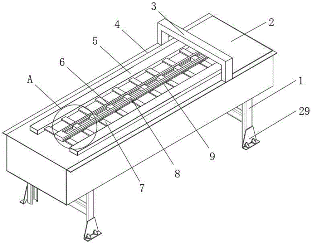
图1为本发明整体立体结构示意图;1 is a schematic diagram of the overall three-dimensional structure of the present invention;
图2为本发明A区域放大结构示意图;Fig. 2 is the enlarged structural schematic diagram of A region of the present invention;
图3为本发明检测台内部结构示意图;3 is a schematic diagram of the internal structure of the detection platform of the present invention;
图4为本发明检测台内部俯视结构示意图;FIG. 4 is a schematic view of the internal top view structure of the detection platform of the present invention;
图5为本发明B区域放大第结构示意图;5 is a schematic view of the enlarged structure of the B region of the present invention;
图6为本发明固定杆和限位槽连接结构示意图;FIG. 6 is a schematic diagram of the connection structure of the fixing rod and the limiting groove of the present invention;
图7为本发明限位杆和连接块连接结构示意图;7 is a schematic diagram of the connection structure of the limit rod and the connecting block of the present invention;
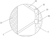
图8为本发明C区域放大结构示意图;8 is a schematic diagram of the enlarged structure of the C region of the present invention;
图9为本发明D区域放大结构示意图;9 is a schematic diagram of the enlarged structure of the D region of the present invention;
图10为本发明上料机构内部结构示意图;10 is a schematic diagram of the internal structure of the feeding mechanism of the present invention;
图中:1、支撑架;2、检测台;3、安装架;4、安装板;5、活动杆;6、基因检测片;7、限位杆;8、输送杆;9、夹持槽;10、固定柱;11、安装槽;12、固定杆;13、拉力弹簧;14、限位板;15、推动板;16、限位槽;17、推杆电机;18、调节弹簧;19、调节槽;20、调节块;21、连接块;22、连接滑槽;23、限位弹簧;24、限位滑块;25、调节杆;26、连接杆;27、稳定块;28、稳定槽;29、角铁;30、上料机构;31、上料壳;32、动力套筒;33、限位挡板;34、动力弹簧;35、动力推杆;36、底板;37、存储槽;38、限位滑槽;39、输送槽。In the figure: 1. Supporting frame; 2. Testing table; 3. Mounting frame; 4. Mounting plate; 5. Active rod; 6. Genetic testing sheet; 7. Limiting rod; 8. Conveying rod; ;10, fixed column; 11, installation slot; 12, fixed rod; 13, tension spring; 14, limit plate; 15, push plate; 16, limit slot; 17, push rod motor; 18, adjustment spring; 19 , adjusting slot; 20, adjusting block; 21, connecting block; 22, connecting chute; 23, limit spring; 24, limit slider; 25, adjusting rod; 26, connecting rod; 27, stabilizing block; 28, Stabilization groove; 29, angle iron; 30, feeding mechanism; 31, feeding shell; 32, power sleeve; 33, limit baffle; 34, power spring; 35, power push rod; 36, bottom plate; 37, Storage slot; 38, limit chute; 39, conveying slot.
具体实施方式Detailed ways
下面将结合实施例对本发明的技术方案进行清楚、完整地描述,显然,所描述的实施例仅仅是本发明一部分实施例,而不是全部的实施例。基于本发明中的实施例,本领域普通技术人员在没有作出创造性劳动前提下所获得的所有其它实施例,都属于本发明保护的范围。The technical solutions of the present invention will be clearly and completely described below with reference to the embodiments. Obviously, the described embodiments are only a part of the embodiments of the present invention, rather than all the embodiments. Based on the embodiments of the present invention, all other embodiments obtained by those of ordinary skill in the art without creative efforts shall fall within the protection scope of the present invention.
请参阅图1-10所示,一种批量检测生物基因的检测设备,包括检测台2,检测台2底部设置有支撑架1,且支撑架1通过螺栓与检测台2固定连接,检测台2顶部对称设置有安装板4,且安装板4焊接固定在检测台2顶部,检测台2顶设置有安装架3,且安装架3通过螺栓与检测台2拆卸式连接,且安装架3底部安装有检测头;Please refer to Fig. 1-10, a detection device for batch detection of biological genes, including a detection table 2, a
检测台2顶部对称设置有活动杆5,检测台2顶部设置有输送杆8,且输送杆8位于两个对称设置的活动杆5之间,输送杆8顶部开设有输送槽39,通过输送槽39的设置,便于检测人员观察检测的运输过程是否出现异常,输送杆8两侧对称开设有夹持槽9,且夹持槽9与输送槽39连通,活动杆5一侧等距固定有限位杆7,限位杆7远离活动杆5的一端设置有连接块21,且连接块21远离限位杆7的一端贯穿夹持槽9设置在输送槽39内,通过连接块21夹持基因检测片6,对基因检测片6进行夹持运输;A
限位杆7和连接块21之间对称设置有调节杆25,且调节杆25的一端通过铰链与连接块21转动连接,限位杆7靠近连接块21的一端开设有限位滑槽38,且限位滑槽38内对称设置有限位滑块24,且两个对称设置的限位滑块24与限位滑槽38滑动连接,通过限位滑块24的设置,避免调节杆25在转动后需要产生连接端点的位置变化,限位滑槽38内设置有限位弹簧23,且限位弹簧23的两端分别与两个对称设置的限位滑块24固定连接,限位弹簧23的设置使得两个对称设置的限位滑块24在挤压限位弹簧23后产生一个反向的推动力,保证连接块21与基因检测片6之间的夹持紧密性,调节杆25远离连接块21的一端通过铰链与对应的限位滑块24转动连接;Between the
限位杆7靠近连接块21的一端与连接块21靠近限位杆7的一端均对称开设有连接滑槽22,且限位杆7和连接块21之间对称设置有连接杆26,且连接杆26的两端分别设置在对应的连接滑槽22内,通过连接杆26的设置,保证限位杆7和连接块21保持横向滑动,连接滑槽22两侧对称开设有稳定槽28,稳定槽28内滑动连接有稳定块27,且稳定块27的一端贯穿稳定槽28与对应的连接杆26固定连接,通过稳定块27和稳定槽28的设置,对连接杆26的滑动距离进行限制,避免连接杆26运动出连接滑槽22;One end of the
检测台2内部开设有安装槽11,活动杆5底部对称固定有固定杆12,且固定杆12底端贯穿检测台2顶部侧壁设置在安装槽11内,固定杆12一侧设置有限位板14,且限位板14与固定杆12相互配合,固定杆12一侧设置有固定柱10,且固定柱10与检测台2固定连接,固定柱10与固定杆12之间设置有拉力弹簧13,且拉力弹簧13的两端分别与固定柱10和固定杆12转动连接,通过拉力弹簧13的设置,使得固定杆12在没有推动力的情况下进行自动回位;An
安装槽11内对称设置有推杆电机17,安装槽11内对称设置有推动板15,且推杆电机17的输出轴端部与推动板15固定连接,推动板15与对应设置的固定杆12相互配合;A
安装槽11底部位于固定杆12的一侧开设有限位槽16,固定杆12底端设置在对应的限位槽16内,限位槽16远一侧开设有调节槽19,调节槽19内滑动连接有调节块20,调节槽19内设置有调节弹簧18,且调节弹簧18的两端分别与调节块20和检测台2固定连接,通过调节弹簧18和调节块20的设置,对固定杆12的运动方向进行限定,避免固定杆12在没有推动力的情况下原路返回;The bottom of the
安装槽11内设置有上料机构30,上料机构30由动力套筒32、限位挡板33、动力弹簧34、动力推杆35和底板36组成,安装槽11内固定连接有上料壳31,上料壳31顶部开设有存储槽37,存储槽37内等距放置有若干个基因检测片6,存储槽37内设置有底板36,且底板36与上料壳31滑动连接,且底板36位于基因检测片6正下方,上料壳31内部固定有动力套筒32,动力套筒32内部滑动连接有动力推杆35,动力推杆35顶部贯穿动力套筒32与底板36固定连接,通过上料机构30的设置,使得基因检测片6进行自动上料,节省人工上料的时间;A
动力套筒32内滑动连接有限位挡板33,且限位挡板33与动力推杆35底端固定连接,动力套筒32内部设置有动力弹簧34,且动力弹簧34的两端分别与限位挡板33和上料壳31固定连接,安装架3底部四角均固定连接有角铁29;The
该种批量检测生物基因的检测设备的使用方法,具体包括下述步骤:The method for using the detection equipment for batch detection of biological genes specifically includes the following steps:
步骤一:当需要对基因检测片6检测时,将存放有基因检测片6的上料结构放入活动杆5正下方,启动推杆电机17,使得推杆电机17带动推动板15运动,使得推动板15向着远离推杆电机17的方向运动,使得固定杆12运动,固定杆12的运动状态分为两种,第一阶段,固定杆12在限位槽16内呈现与推动板15垂直方向的直线运动,从而使得两个对称设置的限位杆7夹紧基因检测片6,第二阶段开始后,固定杆12与限位板14接触,沿着限位板14的斜面滑动,使得限位杆7带动基因检测片6向着安装架3的方向运动,安装架3上的检测头对基因检测片6进行检测;Step 1: When the
步骤二:当步骤一中的第二阶段运行的同时,两个对称设置的限位杆7仍然向着基因检测片6的方向运动,连接块21在基因检测片6的方向推力下,向着限位杆7的方向运动,挤压两个对称设置的调节杆25,由于调节杆25的长度保持不变,调节杆25推动限位滑块24滑动,从而使得限位弹簧23受到压力产生形变,产生一个反向的推动力,使得限位滑块24反向运动,从而使得调节杆25转动,推动连接块21向着远离限位杆7的方向运动;Step 2: While the second stage in
步骤三:当步骤一中的第二阶段结束进行到末尾阶段时,固定杆12与调节块20接触,使得调节块20受到挤压,从而挤压调节弹簧18,调节弹簧18受力产生一个方向的推动力,当固定杆12运动到调节块20的一侧时,调节弹簧18推动调节块20向着远离调节弹簧18的方向运动,将限位槽16的滑道进行封闭;Step 3: When the second stage in
步骤四:当限位槽16的滑道封闭后,推杆电机17处于收缩状态,推动板15对固定杆12的作用力消失,固定杆12在拉力弹簧13的作用下在限位槽16内进行回程,且回程时解除限位杆7对基因检测片6的夹持。Step 4: When the slideway of the
工作原理:working principle:
本发明在使用时,首先,当需要对基因检测片6检测时,将存放有基因检测片6的上料结构放入活动杆5正下方,启动推杆电机17,使得推杆电机17带动推动板15运动,使得推动板15向着远离推杆电机17的方向运动,使得固定杆12运动,固定杆12的运动状态分为两种,第一阶段,固定杆12在限位槽16内呈现与推动板15垂直方向的直线运动,从而使得两个对称设置的限位杆7夹紧基因检测片6,第二阶段开始后,固定杆12与限位板14接触,沿着限位板14的斜面滑动,使得限位杆7带动基因检测片6向着安装架3的方向运动,安装架3上的检测头对基因检测片6进行检测;当步骤一中的第二阶段运行的同时,两个对称设置的限位杆7仍然向着基因检测片6的方向运动,连接块21在基因检测片6的方向推力下,向着限位杆7的方向运动,挤压两个对称设置的调节杆25,由于调节杆25的长度保持不变,调节杆25推动限位滑块24滑动,从而使得限位弹簧23受到压力产生形变,产生一个反向的推动力,使得限位滑块24反向运动,从而使得调节杆25转动,推动连接块21向着远离限位杆7的方向运动;当步骤一中的第二阶段结束进行到末尾阶段时,固定杆12与调节块20接触,使得调节块20受到挤压,从而挤压调节弹簧18,调节弹簧18受力产生一个方向的推动力,当固定杆12运动到调节块20的一侧时,调节弹簧18推动调节块20向着远离调节弹簧18的方向运动,将限位槽16的滑道进行封闭;当限位槽16的滑道封闭后,推杆电机17处于收缩状态,推动板15对固定杆12的作用力消失,固定杆12在拉力弹簧13的作用下在限位槽16内进行回程,且回程时解除限位杆7对基因检测片6的夹持,重复以上操作,对基因检测片6进行流程化检测。When the present invention is in use, firstly, when the
以上公开的本发明优选实施例只是用于帮助阐述本发明。优选实施例并没有详尽叙述所有的细节,也不限制该发明仅为的具体实施方式。显然,根据本说明书的内容,可作很多的修改和变化。本说明书选取并具体描述这些实施例,是为了更好地解释本发明的原理和实际应用,从而使所属技术领域技术人员能很好地理解和利用本发明。本发明仅受权利要求书及其全部范围和等效物的限制。The above-disclosed preferred embodiments of the present invention are provided only to help illustrate the present invention. The preferred embodiments do not describe all the details and do not limit the invention to specific embodiments only. Obviously, many modifications and variations are possible in light of the content of this specification. The present specification selects and specifically describes these embodiments in order to better explain the principles and practical applications of the present invention, so that those skilled in the art can well understand and utilize the present invention. The present invention is to be limited only by the claims and their full scope and equivalents.
Claims (6)
Priority Applications (1)
| Application Number | Priority Date | Filing Date | Title |
|---|---|---|---|
| CN202110656776.9A CN113528309B (en) | 2021-06-11 | 2021-06-11 | A detection device for batch detection of biological genes |
Applications Claiming Priority (1)
| Application Number | Priority Date | Filing Date | Title |
|---|---|---|---|
| CN202110656776.9A CN113528309B (en) | 2021-06-11 | 2021-06-11 | A detection device for batch detection of biological genes |
Publications (2)
| Publication Number | Publication Date |
|---|---|
| CN113528309A CN113528309A (en) | 2021-10-22 |
| CN113528309B true CN113528309B (en) | 2022-05-06 |
Family
ID=78095902
Family Applications (1)
| Application Number | Title | Priority Date | Filing Date |
|---|---|---|---|
| CN202110656776.9A Active CN113528309B (en) | 2021-06-11 | 2021-06-11 | A detection device for batch detection of biological genes |
Country Status (1)
| Country | Link |
|---|---|
| CN (1) | CN113528309B (en) |
Citations (6)
| Publication number | Priority date | Publication date | Assignee | Title |
|---|---|---|---|---|
| JP2005315895A (en) * | 2001-11-28 | 2005-11-10 | Ind Technol Res Inst | Method and apparatus for manufacturing a biochip |
| CN206146955U (en) * | 2016-11-03 | 2017-05-03 | 广州瑞科基因科技有限公司 | Biochip sample presentation mechanism |
| CN108642159A (en) * | 2018-06-27 | 2018-10-12 | 上海百傲科技股份有限公司 | Biological chips detection system |
| CN210037641U (en) * | 2019-04-11 | 2020-02-07 | 泰安京泰生物技术有限公司 | Optical automatic detection device |
| CN210328189U (en) * | 2019-07-01 | 2020-04-14 | 安徽天通精电新科技有限公司 | A PCB fixed establishment for chip mounter |
| CN212845426U (en) * | 2020-07-29 | 2021-03-30 | 周龙飞 | Full-automatic biochip analyzer |
Family Cites Families (1)
| Publication number | Priority date | Publication date | Assignee | Title |
|---|---|---|---|---|
| TWI325494B (en) * | 2006-07-28 | 2010-06-01 | Ind Tech Res Inst | Optical measuring system |
-
2021
- 2021-06-11 CN CN202110656776.9A patent/CN113528309B/en active Active
Patent Citations (6)
| Publication number | Priority date | Publication date | Assignee | Title |
|---|---|---|---|---|
| JP2005315895A (en) * | 2001-11-28 | 2005-11-10 | Ind Technol Res Inst | Method and apparatus for manufacturing a biochip |
| CN206146955U (en) * | 2016-11-03 | 2017-05-03 | 广州瑞科基因科技有限公司 | Biochip sample presentation mechanism |
| CN108642159A (en) * | 2018-06-27 | 2018-10-12 | 上海百傲科技股份有限公司 | Biological chips detection system |
| CN210037641U (en) * | 2019-04-11 | 2020-02-07 | 泰安京泰生物技术有限公司 | Optical automatic detection device |
| CN210328189U (en) * | 2019-07-01 | 2020-04-14 | 安徽天通精电新科技有限公司 | A PCB fixed establishment for chip mounter |
| CN212845426U (en) * | 2020-07-29 | 2021-03-30 | 周龙飞 | Full-automatic biochip analyzer |
Also Published As
| Publication number | Publication date |
|---|---|
| CN113528309A (en) | 2021-10-22 |
Similar Documents
| Publication | Publication Date | Title |
|---|---|---|
| CN107498722B (en) | Self-centering monocrystalline silicon rod clamping mechanism and its working method | |
| CN205341594U (en) | Flat tub of bending machine | |
| CN206382736U (en) | A kind of battery modules welder using full-automatic clamping | |
| CN205069781U (en) | EV battery automatic coating machine | |
| CN206307684U (en) | A kind of working plate circulates production line | |
| CN118719867A (en) | A new energy battery box shaping tool | |
| CN214115766U (en) | Computer housing clamping device | |
| CN211728479U (en) | A tin bar cutting machine feeding device | |
| CN116268259A (en) | Food quick freezer capable of automatically feeding | |
| CN115502278A (en) | A pipe automatic punching device | |
| CN210731467U (en) | An adjustable stroke welding tool for high wear-resistant steel plate | |
| CN218538008U (en) | Storage steering mechanism | |
| CN221836276U (en) | A gantry palletizing robot | |
| CN221719028U (en) | A fully automatic bag folding machine | |
| CN209993684U (en) | Automatic processing device for lithium battery | |
| CN218859370U (en) | Commodity circulation is from transportation goods frame for storage | |
| CN221869830U (en) | Panel bending device | |
| CN113528309A (en) | A detection device for batch detection of biological genes | |
| CN218704300U (en) | Novel grab cup structure | |
| CN218798364U (en) | Hardware strip bending device | |
| CN224101705U (en) | Bending structure for pin bending machine | |
| CN216781863U (en) | A new type of hook claw clamping device | |
| CN219506069U (en) | Large-roll lifting device for heat-shrinkable tape | |
| CN216605923U (en) | Automatic glue dispenser for liquid crystal display production | |
| CN218500280U (en) | Cantilever goods shelf |
Legal Events
| Date | Code | Title | Description |
|---|---|---|---|
| PB01 | Publication | ||
| PB01 | Publication | ||
| SE01 | Entry into force of request for substantive examination | ||
| SE01 | Entry into force of request for substantive examination | ||
| GR01 | Patent grant | ||
| GR01 | Patent grant |