CN113523380B - Precision parts machining digit control machine tool - Google Patents
Precision parts machining digit control machine tool Download PDFInfo
- Publication number
- CN113523380B CN113523380B CN202111078125.2A CN202111078125A CN113523380B CN 113523380 B CN113523380 B CN 113523380B CN 202111078125 A CN202111078125 A CN 202111078125A CN 113523380 B CN113523380 B CN 113523380B
- Authority
- CN
- China
- Prior art keywords
- arc
- servo
- machine tool
- fixedly connected
- ball screw
- Prior art date
- Legal status (The legal status is an assumption and is not a legal conclusion. Google has not performed a legal analysis and makes no representation as to the accuracy of the status listed.)
- Active
Links
- 238000003754 machining Methods 0.000 title claims abstract description 21
- 230000007246 mechanism Effects 0.000 claims abstract description 35
- 230000005540 biological transmission Effects 0.000 claims abstract description 21
- 210000000078 claw Anatomy 0.000 claims abstract description 19
- 238000003801 milling Methods 0.000 claims description 15
- 238000003466 welding Methods 0.000 claims 2
- 230000006978 adaptation Effects 0.000 claims 1
- 238000012545 processing Methods 0.000 abstract description 29
- 238000000034 method Methods 0.000 abstract description 19
- 230000008569 process Effects 0.000 abstract description 17
- 238000013459 approach Methods 0.000 abstract description 3
- 230000007547 defect Effects 0.000 abstract description 3
- 230000008859 change Effects 0.000 description 3
- 238000001179 sorption measurement Methods 0.000 description 3
- 230000000694 effects Effects 0.000 description 2
- 230000003993 interaction Effects 0.000 description 2
- 238000012544 monitoring process Methods 0.000 description 2
- 230000008520 organization Effects 0.000 description 2
- 230000001105 regulatory effect Effects 0.000 description 2
- 230000009286 beneficial effect Effects 0.000 description 1
- 238000004891 communication Methods 0.000 description 1
- 230000001276 controlling effect Effects 0.000 description 1
- 230000001419 dependent effect Effects 0.000 description 1
- 238000001514 detection method Methods 0.000 description 1
- 238000006073 displacement reaction Methods 0.000 description 1
- 230000006872 improvement Effects 0.000 description 1
- 238000004519 manufacturing process Methods 0.000 description 1
- 238000012986 modification Methods 0.000 description 1
- 230000004048 modification Effects 0.000 description 1
Images




Classifications
-
- B—PERFORMING OPERATIONS; TRANSPORTING
- B23—MACHINE TOOLS; METAL-WORKING NOT OTHERWISE PROVIDED FOR
- B23C—MILLING
- B23C3/00—Milling particular work; Special milling operations; Machines therefor
-
- B—PERFORMING OPERATIONS; TRANSPORTING
- B23—MACHINE TOOLS; METAL-WORKING NOT OTHERWISE PROVIDED FOR
- B23Q—DETAILS, COMPONENTS, OR ACCESSORIES FOR MACHINE TOOLS, e.g. ARRANGEMENTS FOR COPYING OR CONTROLLING; MACHINE TOOLS IN GENERAL CHARACTERISED BY THE CONSTRUCTION OF PARTICULAR DETAILS OR COMPONENTS; COMBINATIONS OR ASSOCIATIONS OF METAL-WORKING MACHINES, NOT DIRECTED TO A PARTICULAR RESULT
- B23Q1/00—Members which are comprised in the general build-up of a form of machine, particularly relatively large fixed members
- B23Q1/25—Movable or adjustable work or tool supports
-
- B—PERFORMING OPERATIONS; TRANSPORTING
- B23—MACHINE TOOLS; METAL-WORKING NOT OTHERWISE PROVIDED FOR
- B23Q—DETAILS, COMPONENTS, OR ACCESSORIES FOR MACHINE TOOLS, e.g. ARRANGEMENTS FOR COPYING OR CONTROLLING; MACHINE TOOLS IN GENERAL CHARACTERISED BY THE CONSTRUCTION OF PARTICULAR DETAILS OR COMPONENTS; COMBINATIONS OR ASSOCIATIONS OF METAL-WORKING MACHINES, NOT DIRECTED TO A PARTICULAR RESULT
- B23Q17/00—Arrangements for observing, indicating or measuring on machine tools
- B23Q17/24—Arrangements for observing, indicating or measuring on machine tools using optics or electromagnetic waves
- B23Q17/2409—Arrangements for indirect observation of the working space using image recording means, e.g. a camera
-
- B—PERFORMING OPERATIONS; TRANSPORTING
- B23—MACHINE TOOLS; METAL-WORKING NOT OTHERWISE PROVIDED FOR
- B23Q—DETAILS, COMPONENTS, OR ACCESSORIES FOR MACHINE TOOLS, e.g. ARRANGEMENTS FOR COPYING OR CONTROLLING; MACHINE TOOLS IN GENERAL CHARACTERISED BY THE CONSTRUCTION OF PARTICULAR DETAILS OR COMPONENTS; COMBINATIONS OR ASSOCIATIONS OF METAL-WORKING MACHINES, NOT DIRECTED TO A PARTICULAR RESULT
- B23Q5/00—Driving or feeding mechanisms; Control arrangements therefor
- B23Q5/22—Feeding members carrying tools or work
- B23Q5/34—Feeding other members supporting tools or work, e.g. saddles, tool-slides, through mechanical transmission
- B23Q5/38—Feeding other members supporting tools or work, e.g. saddles, tool-slides, through mechanical transmission feeding continuously
- B23Q5/40—Feeding other members supporting tools or work, e.g. saddles, tool-slides, through mechanical transmission feeding continuously by feed shaft, e.g. lead screw
-
- B—PERFORMING OPERATIONS; TRANSPORTING
- B23—MACHINE TOOLS; METAL-WORKING NOT OTHERWISE PROVIDED FOR
- B23Q—DETAILS, COMPONENTS, OR ACCESSORIES FOR MACHINE TOOLS, e.g. ARRANGEMENTS FOR COPYING OR CONTROLLING; MACHINE TOOLS IN GENERAL CHARACTERISED BY THE CONSTRUCTION OF PARTICULAR DETAILS OR COMPONENTS; COMBINATIONS OR ASSOCIATIONS OF METAL-WORKING MACHINES, NOT DIRECTED TO A PARTICULAR RESULT
- B23Q7/00—Arrangements for handling work specially combined with or arranged in, or specially adapted for use in connection with, machine tools, e.g. for conveying, loading, positioning, discharging, sorting
- B23Q7/04—Arrangements for handling work specially combined with or arranged in, or specially adapted for use in connection with, machine tools, e.g. for conveying, loading, positioning, discharging, sorting by means of grippers
Landscapes
- Engineering & Computer Science (AREA)
- Mechanical Engineering (AREA)
- Physics & Mathematics (AREA)
- Optics & Photonics (AREA)
- Milling Processes (AREA)
- Machine Tool Units (AREA)
Abstract
The invention discloses a precision part machining numerical control machine tool, which comprises a workbench, an electric box, two machine tool mechanisms and servo adjusting claws, wherein the electric box is arranged on one side of the workbench, and each machine tool mechanism comprises an arc-shaped rack; the invention abandons the traditional three-section fixed-axis linear transmission system, applies a group of linear transmission from a Z axis on the basis of the X axis and Y axis linear transmission which are directly responsible for processing parts, keeps two groups of freedom degree outputs, is responsible for adjusting the Z axis output through a thread pair, realizes angle adjustment through a gear pair and a servo transmission system, can be adjusted at any angle under the projection view angle of a plumb surface in the actual process of processing the parts, enables a cutter to be directly and vertically matched with an extension line of a profile curve of a part direction surface, solves the defect of polygon forming in the traditional CNC system, enables the actual processing coefficient of the parts to approach to the theoretical coefficient infinitely, and effectively meets the process requirements of actual precise parts.
Description
Technical Field
The invention relates to the technical field of numerical control machining devices, in particular to a numerical control machine tool for machining precision parts.
Background
The traditional two-axis or three-axis CNC device usually only uses the working surface as a base plane, uses X, Y and Z axis to establish three groups of freedom degrees to output to form three groups of linear transmission, and completes the numerical control processing of parts by means of a step angle and a servo system;
however, in the actual processing process, the processing mode relates to a curved surface structure, in particular to the processing of a precise structure, under a microscopic view angle, no matter how three groups of axial outputs are matched with each other, the processing mode is similar to the forming mode of polygonal modeling; the curvature and fineness of the curved surface are completely dependent on the accuracy of the output of the step angle (generally, the more the decimal value of the output of the step angle, the higher the fineness);
however, the processing mode undoubtedly causes the difference between theory and reality of the product, the stress effect and the service life of the part are easily affected by the change of curvature, and the process effect is not perfect when the processing mode relates to the processing of equipment such as medical treatment, spaceflight, navigation and the like.
For this reason, a precision parts machining numerical control machine tool is proposed.
Disclosure of Invention
In view of the above, embodiments of the present invention are intended to provide a precision part machining numerical control machine tool, so as to solve or alleviate the technical problems in the prior art, and to provide at least one useful choice;
the technical scheme of the embodiment of the invention is realized as follows: the numerical control machine tool for machining the precision parts comprises a workbench, an electric box, two machine tool mechanisms and servo adjusting claws, wherein the electric box is arranged on one side of the workbench, and each machine tool mechanism comprises an arc-shaped rack, three first stepping motors, three first ball screws, two toothed rollers, two servo clamping claws, two electric milling cutters, an arc-shaped sliding rack and two driving mechanisms;
the arc-shaped rack is arranged at the top of the workbench, the outer surface of the first stepping motor is arranged on the outer surface of the arc-shaped rack, the arc-shaped sliding rack is arranged at the upper part of the arc-shaped rack, the driving mechanism is arranged at the top of the arc-shaped rack, and the driving mechanism comprises a connecting frame, a first servo motor, a third ball screw and a sliding frame;
the inner side wall of the sliding frame is fixedly connected with the outer surface of the electric milling cutter, the outer surface of the first servo motor is installed on the outer surface of the connecting frame, an output shaft of the first servo motor is in transmission connection with one end of a threaded rod of the third ball screw through a transmission belt, and a moving nut of the third ball screw is fixedly connected with the outer surface of the sliding frame;
the top of workstation is installed the shell body.
In this embodiment, specifically: the arc sliding table frame comprises an arc sliding frame and a concave groove;
the concave groove is arranged on the inner side wall of the arc-shaped sliding frame, the projection of the vertical plane of the concave groove is higher than that of the external through groove of the arc-shaped sliding frame, a minor arc-shaped gear ring is welded on the inner side wall of the arc-shaped sliding frame, which is close to the first stepping motor, the gear teeth of the minor arc-shaped gear ring are meshed with the gear teeth of the toothed roller, the outer surface of the servo claw is arranged on the top of the arc-shaped sliding frame, and the bottom of the arc-shaped sliding frame is matched with the top of the arc-shaped rack.
Inferior arc ring gear meshes with the profile of tooth roller, and then control arc slip table frame wholly cooperates and realizes the angle modulation in the arc rack to drive actuating mechanism wholly and improve the processing angle, satisfy follow-up processing demand.
In this embodiment, specifically: the arc-shaped sliding frame is connected with the first ball screw in a sliding mode through a concave groove, and the inner side wall of the concave groove is attached to the outer surface of the first ball screw moving nut;
the arc sliding frames of the two sets of arc sliding table frames are respectively matched with a first ball screw moving nut through respective concave grooves, and no matter the arc sliding table frames are adjusted at any angle in the actual operation process, the moving pair formed by the concave grooves and the first ball screw moving nuts can control the arc sliding table frames to perform feeding linear driving, so that the normal function of the machine tool is met.
In this embodiment, specifically: threaded rods of the four first ball screws are fixedly connected with output shafts of the four first stepping motors, and output shafts of the two first stepping motors are fixedly connected with the inner side wall of the toothed roller;
each first stepping motor is responsible for correspondingly driving the first ball screw and the toothed roller matched with the first stepping motor.
In this embodiment, specifically: the top of the arc-shaped rack is welded with a support frame, and the inner side wall of the support frame is rotatably connected with the threaded rod of the first ball screw and the outer surface of the toothed roller through a bearing;
the support frame is responsible for locking the mechanism degree of freedom of first ball screw and profile of tooth roller only, can effectively satisfy mechanism operating stability and life in the actual operation in-process.
In this embodiment, specifically: the driving mechanism further comprises a fixed frame, a second ball screw and a second stepping motor;
the outer surface of the fixing frame is arranged at the top of the arc-shaped sliding frame with the inferior arc-shaped gear ring structure, the outer surface of the second stepping motor is fixedly connected to the outer surface of the fixing frame, an output shaft of the second stepping motor is fixedly connected with a threaded rod of the second ball screw, and a moving nut of the second ball screw is fixedly connected with the outer surface of the connecting frame;
in the driving mechanism, the second stepping motor drives the second ball screw to perform linear transmission, so that the electric milling cutter is driven to perform X-axis adjustment, and the adjustment requirement of subsequent processing stations is met.
In this embodiment, specifically: the servo adjusting claw is arranged on the top of the inner side wall of the outer shell and comprises an upper shell, three second servo motors, three first hinge arms, six third servo motors, six second hinge arms, an electromagnet and a CCD camera;
the outer surface of the upper shell is fixedly connected to the top of the inner side wall of the outer shell, the outer surface of the CCD camera is installed at the bottom of the upper shell, the outer surface of the second servo motor is fixedly connected to the inner side wall of the upper shell, the output shaft of the second servo motor is fixedly connected with the outer surface of the first hinge arm, the outer surfaces of the two third servo motors are installed on the inner side wall of the first hinge arm, the output shafts of the third servo motors are fixedly connected with the outer surface of the second hinge arm, and the bottom of the outer surface of the second hinge arm is hinged to the outer surface of the electromagnet;
the servo adjusting claw is in charge of adjusting the matching angle or posture of a workpiece in the using process, wherein the workpiece is adsorbed and adjusted through the electromagnet, the placing angle and the placing position of the workpiece are detected in real time through the CCD camera, and signal interaction is continuously carried out with an external control system, so that station adjustment is realized;
the electromagnet performs adsorption control through the angle change of the second hinged arm, wherein the second hinged arm is subjected to angle adjustment through the first hinged arm and the third servo motor thereof, and the first hinged arm is subjected to angle adjustment through the second servo motor.
In this embodiment, specifically: the inner side wall of the electrical box is provided with a controller; the controller is used for controlling all the electric elements of the device.
Compared with the prior art, the invention has the beneficial effects that:
1. the invention abandons the traditional three-section fixed-axis linear transmission system, applies a group of linear transmission from a Z axis on the basis of the linear transmission of an X axis and a Y axis which are directly responsible for processing parts, and simultaneously keeps two groups of freedom degree outputs, is responsible for adjusting the Z axis output through a thread pair, and simultaneously realizes angle adjustment through a gear pair and a servo transmission system, and can be adjusted at any angle under the projection view angle of a plumb plane in the actual process of processing the parts, so that a cutter can be directly and vertically matched with an extension line of a profile curve of a part direction plane, the defect of polygonal forming in the traditional CNC system is solved, the actual processing coefficient of the parts approaches to the theoretical coefficient infinitely, and the process requirement of actual precise parts is effectively met;
2. in the actual production process, the six-hinge pair output of the servo adjusting claw can be used for mechanical linkage and mutual matching with the whole machine tool mechanism, and in the angle adjusting process, the moving nut of the first ball screw does not break away from the concave groove kinematic pair matching relation of the arc-shaped sliding frame, so that the linear transmission and angle adjustment of an X shaft and a Y shaft can be seamlessly connected in the process of not influencing the linear adjustment of a Z shaft, the actual processing requirement is met, a CCD camera is used as an automatic detection end, the matching relation and the position angle of a processed plate can be adjusted in an auxiliary mode, and the actual processing requirement is met;
3. according to the numerical control machining device, four groups of machining sections respectively correspond to four directions of the machined part through array arrangement and a special step angle transmission system, and numerical control machining of all working procedures can be finished at one time without manual adjustment;
4. according to the actual processing condition, the electric milling cutters at the two ends of the driving mechanism can respectively correspond to the positions of the two ends of the processed part, the position does not need to be adjusted manually, when part of the part relates to the precise detail position processing, the clamping angle adjustment and the adsorption adjustment of the part can be realized by matching the servo adjusting claw with the servo clamping jaw, and the CCD camera is used as a monitoring and regulating means, so that the actual processing requirement of the precise part is effectively met.
Drawings
In order to more clearly illustrate the embodiments of the present application or the technical solutions in the prior art, the drawings needed to be used in the embodiments or technical descriptions will be briefly described below, it is obvious that the drawings in the following description are only some embodiments of the present application, and for those skilled in the art, other drawings can be obtained according to the drawings without creative efforts.
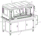
FIG. 1 is a schematic view of a perspective structure according to the present invention;
FIG. 2 is a schematic perspective view of another embodiment of the present invention;
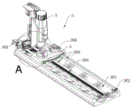
FIG. 3 is a schematic perspective view of a workbench according to the present invention;
FIG. 4 is a schematic perspective view of the machine tool mechanism of the present invention;
FIG. 5 is a schematic perspective view of the enlarged view angle of the area A of FIG. 4 according to the present invention;
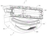
FIG. 6 is a perspective view of the driving mechanism of the present invention;
FIG. 7 is a perspective view of another embodiment of the driving mechanism of the present invention;
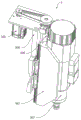
fig. 8 is a schematic perspective view of a servo adjusting claw according to the present invention.
Reference numerals: 1. a work table; 101. an outer housing; 2. an electric box; 201. a controller; 3. a machine tool mechanism; 301. an arc-shaped rack; 302. a support frame; 303. a first stepper motor; 304. a first ball screw; 305. a toothed roll; 306. a servo jack catch; 307. an electric milling cutter; 4. an arc sliding rack; 401. an arcuate carriage; 402. a minor arc-shaped gear ring; 403. a recess groove; 5. a drive mechanism; 501. a fixed mount; 502. a second ball screw; 503. a second stepping motor; 504. a connecting frame; 505. a first servo motor; 506. a third ball screw; 507. a carriage; 6. a servo adjusting claw; 601. an upper housing; 602. a second servo motor; 603. a first hinge arm; 604. a third servo motor; 605. a second hinge arm; 606. an electromagnet; 607. a CCD camera.
Detailed Description
In the following, only certain exemplary embodiments are briefly described. As those skilled in the art will recognize, the described embodiments may be modified in various different ways, all without departing from the spirit or scope of the present invention. Accordingly, the drawings and description are to be regarded as illustrative in nature, and not as restrictive.
The terms "first", "second" and "first" are used for descriptive purposes only and are not to be construed as indicating or implying relative importance or implicitly indicating the number of technical features indicated. Thus, a feature defined as "first" or "second" may explicitly or implicitly include one or more of that feature.
In the present invention, unless otherwise expressly stated or limited, the terms "mounted," "connected," "secured," and the like are to be construed broadly and can, for example, be fixedly connected, detachably connected, or integral; the connection can be mechanical connection, electrical connection or communication; either directly or indirectly through intervening media, either internally or in any other relationship. The specific meanings of the above terms in the present invention can be understood by those skilled in the art according to specific situations.
Examples
Referring to fig. 1-8, the present invention provides a technical solution: the precision parts process the NC machine tool, including work level 1, electric box 2, machine tool organization 3 and servo regulating jaw 6 of two, the electric box 2 is mounted on one side of the work level 1, each machine tool organization 3 includes two arc-shaped platforms 301, three first step motors 303, three first ball screws 304, two tooth-shaped rollers 305, two servo jack catchs 306, two electric milling cutters 307, an arc-shaped sliding platform 4 and two actuating mechanisms 5;
the arc-shaped rack 301 is arranged at the top of the workbench 1, the outer surface of the first stepping motor 303 is arranged at the outer surface of the arc-shaped rack 301, the arc sliding rack 4 is arranged at the upper part of the arc-shaped rack 301, the driving mechanism 5 is arranged at the top of the arc-shaped rack 301, and the driving mechanism 5 comprises a connecting rack 504, a first servo motor 505, a third ball screw 506 and a sliding rack 507;
the inner side wall of the sliding frame 507 is fixedly connected with the outer surface of the electric milling cutter 307, the outer surface of a first servo motor 505 is arranged on the outer surface of the connecting frame 504, the output shaft of the first servo motor 505 is in transmission connection with one end of a threaded rod of a third ball screw 506 through a transmission belt, and a moving nut of the third ball screw 506 is fixedly connected with the outer surface of the sliding frame 507;
an outer housing 101 is mounted on the top of the table 1.
In this embodiment, specifically: the arc slide table frame 4 includes an arc-shaped carriage 401 and a concave groove 403;
the concave groove 403 is formed in the inner side wall of the arc-shaped sliding frame 401, the projection of the vertical plane of the concave groove 403 is higher than the projection of the vertical plane of the external through groove of the arc-shaped sliding frame 401, a inferior arc-shaped gear ring 402 is welded on the inner side wall of the arc-shaped sliding frame 401 close to the first stepping motor 303, the gear teeth of the inferior arc-shaped gear ring 402 are meshed with the gear teeth of the toothed roller 305, the outer surface of the servo claw 306 is installed on the top of the arc-shaped sliding frame 401, and the bottom of the arc-shaped sliding frame 401 is matched with the top of the arc-shaped rack 301;
inferior arc ring gear 402 meshes with profile of tooth roller 305, and then control arc slip table frame 4 whole cooperation realizes the angle modulation in arc rack 301 to drive actuating mechanism 5 whole improvement processing angle, satisfy follow-up processing demand.
In this embodiment, specifically: the arc-shaped sliding frame 401 is connected with the first ball screw 304 in a sliding way through a concave groove 403, and the inner side wall of the concave groove 403 is attached to the outer surface of the moving nut of the first ball screw 304;
the arc sliding carriages 401 of the two sets of arc sliding table frames 4 are respectively matched with a first ball screw 304 moving nut through the respective concave groove 403, and no matter the arc sliding table frames 4 are adjusted at any angle in the actual operation process, the moving pair formed by the concave groove 403 and the first ball screw 304 moving nut can control the arc sliding table frames 4 to perform feeding linear driving, so that the normal function of the machine tool is met.
In this embodiment, specifically: the threaded rods of the three first ball screws 304 are fixedly connected with the output shafts of the four first stepping motors 303, and the output shafts of the two first stepping motors 303 are fixedly connected with the inner side walls of the toothed rollers 305;
each first stepping motor 303 is responsible for driving the first ball screw 304 and the toothed roller 305 engaged therewith, respectively.
In this embodiment, specifically: the top of the arc-shaped rack 301 is welded with a support frame 302, and the inner side wall of the support frame 302 is rotatably connected with the threaded rod of the first ball screw 304 and the outer surface of the toothed roller 305 through a bearing;
the supporting frame 302 is responsible for locking the mechanism freedom degrees of the first ball screw 304 and the toothed roller 305 only, and can effectively meet the requirements of mechanism operation stability and service life in the actual operation process.
In this embodiment, specifically: the driving mechanism 5 further comprises a fixed frame 501, a second ball screw 502 and a second stepping motor 503;
the outer surface of the fixed frame 501 is arranged on the top of an arc-shaped sliding frame 401 with a inferior arc-shaped gear ring 402 structure, the outer surface of a second stepping motor 503 is fixedly connected to the outer surface of the fixed frame 501, the output shaft of the second stepping motor 503 is fixedly connected with the threaded rod of a second ball screw 502, and the moving nut of the second ball screw 502 is fixedly connected with the outer surface of a connecting frame 504;
in the driving mechanism 5, the second stepping motor 503 drives the second ball screw 502 to perform linear transmission, and further drives the electric milling cutter 307 to perform X-axis adjustment, so as to meet the adjustment requirement of the subsequent processing station.
In this embodiment, specifically: the servo adjusting claw 6 is arranged on the top of the inner side wall of the outer shell 101, and the servo adjusting claw 6 comprises an upper shell 601, three second servo motors 602, three first hinge arms 603, six third servo motors 604, six second hinge arms 605, an electromagnet 606 and a CCD camera 607;
the outer surface of the upper shell 601 is fixedly connected to the top of the inner side wall of the outer shell 101, the outer surface of the CCD camera 607 is installed at the bottom of the upper shell 601, the outer surface of the second servo motor 602 is fixedly connected to the inner side wall of the upper shell 601, the output shaft of the second servo motor 602 is fixedly connected with the outer surface of the first hinge arm 603, the outer surfaces of two third servo motors 604 are installed on the inner side wall of the first hinge arm 603, the output shaft of the third servo motor 604 is fixedly connected with the outer surface of the second hinge arm 605, and the bottom of the outer surface of the second hinge arm 605 is hinged to the outer surface of the electromagnet 606;
the servo adjusting claw 6 is responsible for adjusting the matching angle or posture of the workpiece in the using process, wherein the workpiece is adsorbed and adjusted through the electromagnet 606, the placing angle and position of the workpiece are detected in real time through the CCD camera 607, and signal interaction is continuously carried out with an external control system, so that station adjustment is realized;
the electromagnet 606 performs suction control by the angle change of the second hinge arm 605, wherein the second hinge arm 605 is angularly adjusted by the first hinge arm 603 and the third servo motor 604 thereof, and the first hinge arm 603 is angularly adjusted by the second servo motor 602.
In this embodiment, specifically: the inner side wall of the electric box 2 is provided with a controller 201; the controller 201 is used to control all the electrical components of the apparatus.
Working principle or structural principle: when the numerical control machining device is used, a workpiece to be machined is arranged on the servo clamping jaw 306 to be fixed, and then the workpiece is input into the numerical control system and the servo transmission system;
when a workpiece is machined, the Z-axis distance between the workpiece and the electric milling cutter 307 is automatically adjusted by two groups of arc-shaped sliding frames 401, and the first stepping motor 303 transmits torque to the first ball screw 304 to drive the moving nuts of the first ball screw 304 to be respectively matched in the concave grooves 403 of the arc-shaped sliding frames 401, so that linear displacement is realized;
the electric milling cutter 307 is responsible for turning the part, and the X axis and the Y axis of the electric milling cutter are adjusted by respectively transmitting torque to the second ball screw 502 by the second stepping motor 503 and transmitting torque to the third ball screw 506 by the first servo motor 505;
meanwhile, according to the precision and curvature requirements of the part, in the machining process of an X axis and a Y axis of the part, a servo system can drive the toothed roller 305 to perform angle adjustment through the first stepping motor 303, so that the integral X axis and Y axis of the driving mechanism 5 are driven to perform angle adjustment compared with a base point of the workbench 1, the adjustment can be performed at any angle under the projection view angle of a vertical plane when the part is machined, the electric milling cutter 307 can be directly and vertically matched with an extension line of a profile curve of the part direction plane, the defect of polygon forming in the traditional CNC system is overcome, the actual machining coefficient of the part approaches to the theoretical coefficient infinitely, and the process requirement of the actual precision part is effectively met; meanwhile, in the process of angle adjustment, the moving nut of the first ball screw 304 does not break away from the matching relationship of the concave groove 403 kinematic pair of the arc-shaped sliding frame 401, so that the linear transmission and angle adjustment of the X axis and the Y axis can be seamlessly connected in the process of not influencing the linear adjustment of the Z axis, and the actual processing requirement is met;
meanwhile, according to the actual processing condition, the electric milling cutters 307 at the two ends of the driving mechanism 5 can respectively correspond to the two end positions of the processed part, the position does not need to be adjusted manually, when part of the part relates to the precise detail position processing, the clamping angle adjustment and the adsorption adjustment of the part can be realized by matching the servo adjusting claw 6 with the servo clamping claw 306, and the CCD camera 607 is used as a monitoring and adjusting means, so that the actual processing requirement of the precise part is effectively met.
While the invention has been described with reference to specific embodiments, it will be understood by those skilled in the art that various changes and modifications may be made without departing from the spirit and scope of the invention. Therefore, the protection scope of the present invention shall be subject to the protection scope of the appended claims.
Claims (7)
1. Precision parts machining digit control machine tool, be lathe mechanism (3) and servo regulation claw (6) that two, its characterized in that including workstation (1), electric box (2), quantity: the electric box (2) is arranged on one side of the workbench (1), and each machine tool mechanism (3) comprises an arc-shaped rack (301), three first stepping motors (303), three first ball screws (304), two toothed rollers (305), two servo jaws (306), two electric milling cutters (307), an arc-shaped sliding rack (4) and two driving mechanisms (5);
the arc-shaped rack (301) is mounted at the top of the workbench (1), the outer surface of the first stepping motor (303) is mounted at the outer surface of the arc-shaped rack (301), the arc sliding rack (4) is mounted at the upper part of the arc-shaped rack (301), the driving mechanism (5) is mounted at the top of the arc-shaped rack (301), and the driving mechanism (5) comprises a connecting frame (504), a first servo motor (505), a third ball screw (506) and a sliding frame (507);
the inner side wall of the carriage (507) is fixedly connected with the outer surface of the electric milling cutter (307), the outer surface of the first servo motor (505) is installed on the outer surface of the connecting frame (504), the output shaft of the first servo motor (505) is in transmission connection with one end of the threaded rod of the third ball screw (506) through a transmission belt, and the moving nut of the third ball screw (506) is fixedly connected with the outer surface of the carriage (507);
the top of the workbench (1) is provided with an outer shell (101);
the arc sliding rack (4) comprises an arc sliding frame (401) and a concave groove (403);
recess groove (403) are seted up in the inside wall of arc balladeur train (401), the plumb plane projection of recess groove (403) is higher than the plumb plane projection of the outside logical groove of arc balladeur train (401), is close to first step motor (303) the inside wall welding of arc balladeur train (401) has inferior arc ring gear (402), the teeth of a cogwheel of inferior arc ring gear (402) with the teeth of a cogwheel meshing of profile roller (305), the surface of servo jack catch (306) install in the top of arc balladeur train (401), the bottom of arc balladeur train (401) with the top looks adaptation of arc rack (301).
2. The precision parts machining numerical control machine tool according to claim 1, characterized in that: the arc-shaped sliding frame (401) is connected with the first ball screw (304) in a sliding mode through a concave groove (403), and the inner side wall of the concave groove (403) is attached to the outer surface of the moving nut of the first ball screw (304).
3. The precision parts machining numerical control machine tool according to claim 1, characterized in that: threaded rods of the four first ball screws (304) are fixedly connected with output shafts of the four first stepping motors (303), and output shafts of the two first stepping motors (303) are fixedly connected with inner side walls of the toothed rollers (305).
4. The precision parts machining numerical control machine tool according to claim 1, characterized in that: the top welding of arc rack (301) has support frame (302), the inside wall of support frame (302) through the bearing with the threaded rod of first ball (304) and the surface of profile of tooth roller (305) is rotated and is connected.
5. The precision parts machining numerical control machine tool according to claim 1, characterized in that: the driving mechanism (5) further comprises a fixed frame (501), a second ball screw (502) and a second stepping motor (503);
the outer surface of the fixed frame (501) is arranged at the top of the arc-shaped sliding frame (401) with the inferior arc-shaped gear ring (402), the outer surface of the second stepping motor (503) is fixedly connected to the outer surface of the fixed frame (501), the output shaft of the second stepping motor (503) is fixedly connected with the threaded rod of the second ball screw (502), and the moving nut of the second ball screw (502) is fixedly connected with the outer surface of the connecting frame (504).
6. The precision parts machining numerical control machine tool according to claim 1, characterized in that: the servo adjusting claw (6) is installed at the top of the inner side wall of the outer shell (101), and the servo adjusting claw (6) comprises an upper shell (601), three second servo motors (602), three first hinge arms (603), six third servo motors (604), six second hinge arms (605), an electromagnet (606) and a CCD camera (607);
the outer surface of the upper shell (601) is fixedly connected to the top of the inner side wall of the outer shell (101), the outer surface of the CCD camera (607) is installed at the bottom of the upper shell (601), the outer surface of the second servo motor (602) is fixedly connected to the inner side wall of the upper shell (601), the output shaft of the second servo motor (602) is fixedly connected with the outer surface of the first hinge arm (603), the outer surfaces of the two third servo motors (604) are installed on the inner side wall of the first hinge arm (603), the output shaft of the third servo motor (604) is fixedly connected with the outer surface of the second hinge arm (605), and the bottom of the outer surface of the second hinge arm (605) is hinged to the outer surface of the electromagnet (606).
7. The precision parts machining numerical control machine tool according to claim 1, characterized in that: and a controller (201) is installed on the inner side wall of the electrical box (2).
Priority Applications (1)
| Application Number | Priority Date | Filing Date | Title |
|---|---|---|---|
| CN202111078125.2A CN113523380B (en) | 2021-09-15 | 2021-09-15 | Precision parts machining digit control machine tool |
Applications Claiming Priority (1)
| Application Number | Priority Date | Filing Date | Title |
|---|---|---|---|
| CN202111078125.2A CN113523380B (en) | 2021-09-15 | 2021-09-15 | Precision parts machining digit control machine tool |
Publications (2)
| Publication Number | Publication Date |
|---|---|
| CN113523380A CN113523380A (en) | 2021-10-22 |
| CN113523380B true CN113523380B (en) | 2021-11-26 |
Family
ID=78092613
Family Applications (1)
| Application Number | Title | Priority Date | Filing Date |
|---|---|---|---|
| CN202111078125.2A Active CN113523380B (en) | 2021-09-15 | 2021-09-15 | Precision parts machining digit control machine tool |
Country Status (1)
| Country | Link |
|---|---|
| CN (1) | CN113523380B (en) |
Families Citing this family (1)
| Publication number | Priority date | Publication date | Assignee | Title |
|---|---|---|---|---|
| CN117260393A (en) * | 2023-09-07 | 2023-12-22 | 深圳市亿图视觉自动化技术有限公司 | An automatic calibration system and method for guide rail straightness |
Family Cites Families (6)
| Publication number | Priority date | Publication date | Assignee | Title |
|---|---|---|---|---|
| CN202701796U (en) * | 2012-08-31 | 2013-01-30 | 张雪银 | Gradient workbench |
| KR20160074941A (en) * | 2014-12-19 | 2016-06-29 | 황옥상 | Workpiece processing tool of milling machine |
| CN109434188A (en) * | 2018-12-29 | 2019-03-08 | 浙江畅尔智能装备股份有限公司 | A kind of workbench for broaching lathe |
| CN209477725U (en) * | 2019-01-30 | 2019-10-11 | 长春伦艺机电设备有限公司 | Card car aluminum vehicle wheel air holes processes digital-control two-head drilling-boring machine bed |
| CN211219632U (en) * | 2019-09-24 | 2020-08-11 | 深圳市亚的斯机电有限公司 | Clamping device and numerical control machine tool |
| CN212526213U (en) * | 2020-07-07 | 2021-02-12 | 株洲和信工模具有限公司 | High efficiency milling machine chamfer frock |
-
2021
- 2021-09-15 CN CN202111078125.2A patent/CN113523380B/en active Active
Also Published As
| Publication number | Publication date |
|---|---|
| CN113523380A (en) | 2021-10-22 |
Similar Documents
| Publication | Publication Date | Title |
|---|---|---|
| CN110103116A (en) | A kind of main passive compliance grinding and polishing apparatus and grinding and polishing robot of Adaptive Attitude | |
| CN110103114B (en) | Three-degree-of-freedom self-adaptive flexible grinding and polishing device for large complex curved surface and robot | |
| WO2021027245A1 (en) | Multi-robot machining apparatus for complex surface part | |
| CN1904782A (en) | Binocular active vision monitor suitable for precision machining | |
| KR20110012092A (en) | 3-axis robot and gantry type machining system | |
| CN117283345A (en) | A horizontal processing machine tool | |
| CN117139679A (en) | Brake pad flexible CNC drilling device and control system | |
| CN113523380A (en) | Precision parts machining digit control machine tool | |
| JPH0283118A (en) | Electric discharge machining method and device for metallic work | |
| CN114074200A (en) | Numerical control gear grinding machine | |
| CN104625911B (en) | Workpiece deburring processing equipment | |
| CN121061601A (en) | Horizontal eight-axis five-linkage turning and milling compound machine tool based on series-parallel robot | |
| WO2022021576A1 (en) | Numerical-control gear grinding machine | |
| CN210677202U (en) | Numerical control gear milling machine | |
| CN120362957A (en) | Workpiece bidirectional processing equipment based on double-sided drilling and tapping structure | |
| CN106994642A (en) | Hybrid polishing machine | |
| CN111360552A (en) | A seven-axis machine tool | |
| CN219747180U (en) | Horizontal machine tool | |
| CN1106911C (en) | Multifunctional regulating platform | |
| CN223903392U (en) | Numerical control machine tool fine adjustment device for improving machining precision | |
| CN215238067U (en) | Milling device for small Teflon workpiece | |
| CN120921250A (en) | Polishing device for low alloy steel upright post base | |
| CN208245526U (en) | A kind of curling machine device | |
| CN113714829A (en) | Large-size three-axis automatic posture adjustment tool design and operation method | |
| CN222791200U (en) | A five-axis precision adjustment table |
Legal Events
| Date | Code | Title | Description |
|---|---|---|---|
| PB01 | Publication | ||
| PB01 | Publication | ||
| SE01 | Entry into force of request for substantive examination | ||
| SE01 | Entry into force of request for substantive examination | ||
| GR01 | Patent grant | ||
| GR01 | Patent grant |