CN113510846A - Supporting mud construction process for controlling shield construction settlement - Google Patents
Supporting mud construction process for controlling shield construction settlement Download PDFInfo
- Publication number
- CN113510846A CN113510846A CN202110380045.6A CN202110380045A CN113510846A CN 113510846 A CN113510846 A CN 113510846A CN 202110380045 A CN202110380045 A CN 202110380045A CN 113510846 A CN113510846 A CN 113510846A
- Authority
- CN
- China
- Prior art keywords
- wall
- fixedly connected
- box body
- water
- settlement
- Prior art date
- Legal status (The legal status is an assumption and is not a legal conclusion. Google has not performed a legal analysis and makes no representation as to the accuracy of the status listed.)
- Pending
Links
- 238000010276 construction Methods 0.000 title claims abstract description 49
- 238000000034 method Methods 0.000 title claims abstract description 19
- XLYOFNOQVPJJNP-UHFFFAOYSA-N water Substances O XLYOFNOQVPJJNP-UHFFFAOYSA-N 0.000 claims abstract description 63
- 238000003756 stirring Methods 0.000 claims description 27
- 230000002093 peripheral effect Effects 0.000 claims description 6
- 238000007599 discharging Methods 0.000 claims description 5
- 238000005485 electric heating Methods 0.000 claims description 4
- 239000002994 raw material Substances 0.000 abstract description 15
- 238000002156 mixing Methods 0.000 abstract description 9
- 239000012535 impurity Substances 0.000 abstract description 5
- 230000000694 effects Effects 0.000 description 4
- 230000000670 limiting effect Effects 0.000 description 4
- 239000000203 mixture Substances 0.000 description 3
- 238000007790 scraping Methods 0.000 description 3
- 238000003466 welding Methods 0.000 description 3
- 238000004140 cleaning Methods 0.000 description 2
- 230000007547 defect Effects 0.000 description 2
- 238000012423 maintenance Methods 0.000 description 2
- 230000002547 anomalous effect Effects 0.000 description 1
- 230000009286 beneficial effect Effects 0.000 description 1
- 238000010586 diagram Methods 0.000 description 1
- 238000005516 engineering process Methods 0.000 description 1
- 239000003292 glue Substances 0.000 description 1
- 230000001788 irregular Effects 0.000 description 1
- 239000000463 material Substances 0.000 description 1
- 238000005406 washing Methods 0.000 description 1
- 239000003643 water by type Substances 0.000 description 1
Images
Classifications
-
- B—PERFORMING OPERATIONS; TRANSPORTING
- B28—WORKING CEMENT, CLAY, OR STONE
- B28C—PREPARING CLAY; PRODUCING MIXTURES CONTAINING CLAY OR CEMENTITIOUS MATERIAL, e.g. PLASTER
- B28C5/00—Apparatus or methods for producing mixtures of cement with other substances, e.g. slurries, mortars, porous or fibrous compositions
- B28C5/08—Apparatus or methods for producing mixtures of cement with other substances, e.g. slurries, mortars, porous or fibrous compositions using driven mechanical means affecting the mixing
- B28C5/10—Mixing in containers not actuated to effect the mixing
- B28C5/12—Mixing in containers not actuated to effect the mixing with stirrers sweeping through the materials, e.g. with incorporated feeding or discharging means or with oscillating stirrers
- B28C5/16—Mixing in containers not actuated to effect the mixing with stirrers sweeping through the materials, e.g. with incorporated feeding or discharging means or with oscillating stirrers the stirrers having motion about a vertical or steeply inclined axis
-
- B—PERFORMING OPERATIONS; TRANSPORTING
- B08—CLEANING
- B08B—CLEANING IN GENERAL; PREVENTION OF FOULING IN GENERAL
- B08B9/00—Cleaning hollow articles by methods or apparatus specially adapted thereto
- B08B9/08—Cleaning containers, e.g. tanks
- B08B9/087—Cleaning containers, e.g. tanks by methods involving the use of tools, e.g. brushes, scrapers
-
- B—PERFORMING OPERATIONS; TRANSPORTING
- B28—WORKING CEMENT, CLAY, OR STONE
- B28C—PREPARING CLAY; PRODUCING MIXTURES CONTAINING CLAY OR CEMENTITIOUS MATERIAL, e.g. PLASTER
- B28C5/00—Apparatus or methods for producing mixtures of cement with other substances, e.g. slurries, mortars, porous or fibrous compositions
- B28C5/08—Apparatus or methods for producing mixtures of cement with other substances, e.g. slurries, mortars, porous or fibrous compositions using driven mechanical means affecting the mixing
- B28C5/0887—Apparatus or methods for producing mixtures of cement with other substances, e.g. slurries, mortars, porous or fibrous compositions using driven mechanical means affecting the mixing provided with sieves or filters
-
- B—PERFORMING OPERATIONS; TRANSPORTING
- B28—WORKING CEMENT, CLAY, OR STONE
- B28C—PREPARING CLAY; PRODUCING MIXTURES CONTAINING CLAY OR CEMENTITIOUS MATERIAL, e.g. PLASTER
- B28C5/00—Apparatus or methods for producing mixtures of cement with other substances, e.g. slurries, mortars, porous or fibrous compositions
- B28C5/46—Arrangements for applying super- or sub-atmospheric pressure during mixing; Arrangements for cooling or heating during mixing, e.g. by introducing vapour
- B28C5/466—Heating, e.g. using steam
Landscapes
- Engineering & Computer Science (AREA)
- Mechanical Engineering (AREA)
- Structural Engineering (AREA)
- Excavating Of Shafts Or Tunnels (AREA)
Abstract
The invention discloses a supporting mud construction process for controlling shield construction settlement, which comprises a box body, wherein a water tank is fixedly connected to the outer wall of one end of the box body, a water guide groove is fixedly connected to the top of the outer wall of the periphery of the box body, a water delivery pipe is fixedly connected between the middle position of the outer bottom of one end of the water guide groove and the outer wall of the top of the water tank, a rotating motor is fixedly connected to the middle position of the outer wall of the bottom of the box body, a main shaft is fixedly connected to one end of an output shaft of the rotating motor, connecting columns distributed at equal intervals are fixedly connected to the outer wall of the circumference of the main shaft, and a square frame is fixedly connected to the outer wall of the other end of each connecting column. According to the invention, the blending of the support mud and the next construction are realized, the water in the water tank is pumped into the water guide groove by the water pump and then flows out of the water outlet head, the water in the water tank is heated by the hot bar, the filter screen can intercept large impurities in the support mud raw material, and the pulling plate and the filter screen can be pulled out by pulling the handle.
Description
Technical Field
The invention relates to the technical field of shield construction, in particular to a construction process of support mud for controlling shield construction settlement.
Background
The very important auxiliary means in the shield construction is the grouting construction after the wall, the development is very rapid, in the grouting construction, the geological conditions have decisive factors for the selection of grouting materials, the grouting amount, the grouting pressure and the grouting speed are key parameters in the grouting construction, and the proper grouting amount and the proper grouting pressure are the guarantee of the grouting quality.
At present, in shield construction, the requirement for the construction process of supporting mud is also higher and higher, after all, concerns the safety of staff, but current construction equipment still has the defect in the aspect of stirring and mixing the supporting mud, and the stirring is not thorough, and the potential safety hazard to the staff is still comparatively great, therefore, need to design shield construction settlement control and support mud construction process and solve above-mentioned problem urgently.
Disclosure of Invention
The invention aims to solve the defects in the prior art, and provides a supporting mud construction process for controlling the settlement of shield construction.
In order to achieve the purpose, the invention adopts the following technical scheme:
shield constructs construction settlement control with supporting mud construction technology, the power distribution box comprises a box body, the one end outer wall fixedly connected with water tank of box, and the outer wall top fixedly connected with guiding gutter all around of box, fixedly connected with raceway between the outer bottom intermediate position of one end of guiding gutter and the top outer wall of water tank, the bottom outer wall intermediate position fixedly connected with rotating electrical machines of box, the output shaft one end fixedly connected with main shaft of rotating electrical machines, the circumference outer wall fixedly connected with equidistance of main shaft distributes the spliced pole, and the equal fixedly connected with square frame of the other end outer wall of spliced pole, the equal fixedly connected with stirring net of inner wall all around of square frame, the bottom outer wall one end fixedly connected with discharging pipe of box.
Preferably, the top inner wall of water tank fixedly connected with water pump, and the bottom outer wall fixedly connected with inlet tube of water pump, fixedly connected with electric heat bar between the bottom both ends inner wall of water tank.
Preferably, an inclined baffle is fixedly connected between the inner walls of the two ends of the top of the box body, and filter screens are fixedly connected to the tops of the inner walls around the box body.
Preferably, the outer wall of one side of box is opened there is the bar mouth, and the outer wall of bar mouth is pegged graft and is had the arm-tie, and one side outer wall fixed connection of arm-tie is in one side outer wall of filter screen, and the opposite side outer wall fixed connection of arm-tie has the handle.
Preferably, the top of the peripheral inner wall of the box body is fixedly connected with a fixing frame, the top outer wall of the main shaft is rotatably connected with the bottom outer wall of the fixing frame through a bearing, and the peripheral outer wall of the bottom of the water guide groove is fixedly connected with water outlet heads distributed at equal intervals.
Preferably, the circumference outer wall intermediate position fixedly connected with horizontal pole of main shaft, and the equal fixedly connected with scraper blade of the other end outer wall of horizontal pole, the equal fixedly connected with support column in bottom outer wall four corners of box.
Preferably, the connecting posts are replaced by equidistantly spaced springs.
The invention has the beneficial effects that:
1. through the box body, the rotating motor, the main shaft, the cross bar, the scraping plate, the stirring net, the water pump, the water tank, the electric heating bar, the water chute, the water outlet head and the discharging pipe, when the device is used by a worker, the supporting mud raw materials can be directly put into the box body, the rotating motor is started, the main shaft and the stirring net can be driven to stir and mix the supporting mud raw material which is put into the box body, the blending of the supporting mud and the next construction are realized, the water pump is started, the water in the water tank can be pumped into the water chute, and then flow from the play flood peak, on the one hand support the mixing velocity of mud with higher speed, on the other hand is to the box inner wall moisten that waters all around, makes things convenient for the scraper blade to glue and scrapes down at the support mud raw materials of box inner wall, has realized maintenance and washing to the box, and the electric rod can heat the water in the water tank, further accelerates mixing and abluent speed.
2. Through the slope baffle that sets up, the filter screen, arm-tie and handle, when the staff will support the mud raw materials and drop into in the box, the slope backup pad can carry out appropriate current limiting effect, it is too much to prevent to get into the support mud raw materials that stir the flow, influence the effect of stirring, the filter screen can be with the bold impurity part interception in supporting the mud raw materials, prevent to exert an influence to subsequent stirring and ejection of compact, when remaining too much impurity on the filter screen, can directly stimulate the handle, take arm-tie and filter screen out and wash and change, the service life of equipment has been increased.
3. Through the spring that sets up, when the stirring net stirs the mixture to the raw materials in the box, the inhomogeneous condition of stirring may appear, through changing the spliced pole into the spring this moment, can be when the main shaft is rotatory, applys anomalous pendulum power to the stirring net, makes the effect of stirring better.
Drawings
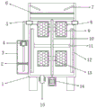
Fig. 1 is a schematic front cross-sectional structural view of a supporting mud construction process for controlling shield construction settlement proposed in embodiment 1;
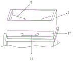
fig. 2 is a schematic structural view of a pulling plate of the supporting mud construction process for controlling the settlement of shield construction provided in embodiment 1;
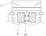
fig. 3 is a schematic diagram of a spring structure of the supporting mud construction process for controlling the shield construction settlement in embodiment 2.
In the figure: the device comprises a box body 1, an electric heating rod 2, a water tank 3, a water pump 4, a water chute 5, a filter screen 6, an inclined baffle 7, a water outlet head 8, a stirring net 9, a main shaft 10, a cross rod 11, a scraping plate 12, a connecting column 13, a rotating motor 14, a discharging pipe 15, a handle 16, a pulling plate 17 and a spring 18.
Detailed Description
The technical solution of the present patent will be described in further detail with reference to the following embodiments.
Reference will now be made in detail to embodiments of the present patent, examples of which are illustrated in the accompanying drawings, wherein like or similar reference numerals refer to the same or similar elements or elements having the same or similar function throughout. The embodiments described below with reference to the drawings are exemplary only for the purpose of explaining the present patent and are not to be construed as limiting the present patent.
In the description of this patent, it is to be understood that the terms "center," "upper," "lower," "front," "rear," "left," "right," "vertical," "horizontal," "top," "bottom," "inner," "outer," and the like are used in the orientations and positional relationships indicated in the drawings for the convenience of describing the patent and for the simplicity of description, and are not intended to indicate or imply that the referenced devices or elements must have a particular orientation, be constructed and operated in a particular orientation, and are not to be considered limiting of the patent.
In the description of this patent, it is noted that unless otherwise specifically stated or limited, the terms "mounted," "connected," and "disposed" are to be construed broadly and can include, for example, fixedly connected, disposed, detachably connected, disposed, or integrally connected and disposed. The specific meaning of the above terms in this patent may be understood by those of ordinary skill in the art as appropriate.
Example 1
Referring to fig. 1-2, the supporting mud construction process for controlling shield construction settlement comprises a box body 1, the outer wall of one end of the box body 1 is connected with a water tank 3 through bolts, the top of the outer wall of the periphery of the box body 1 is connected with a water guide groove 5 through bolts, a water delivery pipe is welded between the middle position of the outer bottom of one end of the water guide groove 5 and the outer wall of the top of the water tank 3, the middle position of the outer wall of the bottom of the box body 1 is connected with a rotating motor 14 through bolts, one end of an output shaft of the rotating motor 14 is connected with a main shaft 10 through bolts, connecting columns 13 distributed equidistantly are welded on the outer wall of the circumference of the main shaft 10, a square frame is welded on the outer wall of the other end of the connecting columns 13, a stirring net 9 is connected on the inner wall of the periphery of the square frame through bolts, and a discharging pipe 15 is welded on one end of the outer wall of the bottom of the box body 1.
Wherein, there is water pump 4 top inner wall of water tank 3 through bolted connection, and the bottom outer wall welding of water pump 4 has the inlet tube, has electrical bar 2 between the bottom both ends inner wall of water tank 3 through bolted connection.
Wherein, the welding has the slope baffle 7 between the top both ends inner wall of box 1, and the inner wall top all around of box 1 has filter screen 6 through bolted connection.
Wherein, the outer wall of one side of box 1 is opened there is the bar mouth, and the outer wall of bar mouth is pegged graft and is had arm-tie 17, and the outer wall of one side of arm-tie 17 welds in the outer wall of one side of filter screen 6, and there is handle 16 on the opposite side outer wall of arm-tie 17 through bolted connection.
Wherein, the top of the inner wall all around of box 1 has the mount through bolted connection, and the top outer wall of main shaft 10 passes through the bearing and rotates to be connected in the bottom outer wall of mount, and the bottom of guiding gutter 5 outer wall all around all welds the outlet head 8 that the equidistance distributes.
Wherein, the welding of the circumference outer wall intermediate position of main shaft 10 has horizontal pole 11, and the other end outer wall of horizontal pole 11 all has scraper blade 12 through bolted connection, and the support column has all been welded in the bottom outer wall four corners of box 1.
The working principle is as follows: when the device is used, when a worker uses the device, the supporting mud raw material can be directly put into the box body 1, the rotating motor 14 is started, the main shaft 10 and the stirring net 9 can be driven to stir and mix the supporting mud raw material put into the box body 1, the blending and next construction of the supporting mud are realized, the water pump 4 is started, the water in the water tank 3 can be pumped into the water guiding groove 5 and then flows out from the water outlet head 8, on one hand, the mixing speed of the supporting mud is accelerated, on the other hand, the water is watered and moistened on the peripheral inner wall of the box body 1, the supporting mud raw material adhered on the inner wall of the box body 1 is conveniently scraped by the scraping plate 12, the maintenance and cleaning of the box body 1 are realized, the electric heating rod 2 can heat the water in the water tank 3, the mixing and cleaning speed are further accelerated, when the worker puts the supporting mud raw material into the box body 1, the inclined supporting plate 7 can perform proper current limiting function, prevent to get into the support mud raw materials of stirring flow too much, influence the effect of stirring, filter screen 6 can prevent to produce the influence to subsequent stirring and ejection of compact with the bold impurity part interception in supporting the mud raw materials, when remaining too much impurity on filter screen 6, can directly stimulate handle 16, take out arm-tie 17 and filter screen 6 and wash and change, increased the life of equipment.
Example 2
Referring to fig. 3, in the supporting mud construction process for controlling shield construction settlement, compared to embodiment 1, the present embodiment replaces the connecting columns 13 with springs 18 distributed at equal intervals.
The working principle is as follows: when the stirring net 9 is used for stirring and mixing the raw materials in the box body 1, uneven stirring can occur, and at the moment, the connecting column 13 is replaced by the spring 18, so that irregular swinging force can be applied to the stirring net 9 when the main shaft 10 rotates, and the stirring effect is better.
The above description is only for the preferred embodiment of the present invention, but the scope of the present invention is not limited thereto, and any person skilled in the art should be considered to be within the technical scope of the present invention, and the technical solutions and the inventive concepts thereof according to the present invention should be equivalent or changed within the scope of the present invention.
Claims (7)
1. The supporting mud construction process for controlling the shield construction settlement comprises a box body (1) and is characterized in that the outer wall of one end of the box body (1) is fixedly connected with a water tank (3), and the top of the peripheral outer wall of the box body (1) is fixedly connected with a water chute (5), a water delivery pipe is fixedly connected between the middle position of the outer bottom of one end of the water chute (5) and the outer wall of the top of the water tank (3), the middle position of the outer wall of the bottom of the box body (1) is fixedly connected with a rotating motor (14), one end of an output shaft of the rotating motor (14) is fixedly connected with a main shaft (10), the outer wall of the circumference of the main shaft (10) is fixedly connected with connecting columns (13) which are distributed at equal intervals, and the outer wall of the other end of the connecting column (13) is fixedly connected with a square frame, the inner walls around the square frame are fixedly connected with a stirring net (9), and one end of the outer wall of the bottom of the box body (1) is fixedly connected with a discharging pipe (15).
2. The supporting mud construction process for controlling the settlement of shield construction according to claim 1, wherein a water pump (4) is fixedly connected to the inner wall of the top of the water tank (3), a water inlet pipe is fixedly connected to the outer wall of the bottom of the water pump (4), and an electric heating rod (2) is fixedly connected between the inner walls of the two ends of the bottom of the water tank (3).
3. The supporting mud construction process for controlling the settlement of shield construction according to claim 2, wherein an inclined baffle (7) is fixedly connected between the inner walls of the two ends of the top of the box body (1), and a filter screen (6) is fixedly connected to the top of the inner wall around the box body (1).
4. The supporting mud construction process for controlling the settlement of the shield construction according to claim 3, wherein a strip-shaped opening is formed in the outer wall of one side of the box body (1), a pulling plate (17) is inserted into the outer wall of the strip-shaped opening, the outer wall of one side of the pulling plate (17) is fixedly connected to the outer wall of one side of the filter screen (6), and a handle (16) is fixedly connected to the outer wall of the other side of the pulling plate (17).
5. The supporting mud construction process for controlling the settlement of shield construction according to claim 4, wherein the top of the peripheral inner wall of the box body (1) is fixedly connected with a fixed frame, the top outer wall of the main shaft (10) is rotatably connected with the bottom outer wall of the fixed frame through a bearing, and the peripheral outer walls of the bottom of the water chute (5) are fixedly connected with water outlets (8) distributed at equal intervals.
6. The supporting mud construction process for controlling the settlement of the shield construction according to any one of claims 1 to 5, wherein a cross bar (11) is fixedly connected to the middle position of the outer wall of the circumference of the main shaft (10), scrapers (12) are fixedly connected to the outer wall of the other end of the cross bar (11), and supporting columns are fixedly connected to four corners of the outer wall of the bottom of the box body (1).
7. The supporting mud construction process for controlling the settlement of shield construction according to claim 1, wherein the connecting columns (13) are replaced with springs (18) distributed equidistantly.
Priority Applications (1)
| Application Number | Priority Date | Filing Date | Title |
|---|---|---|---|
| CN202110380045.6A CN113510846A (en) | 2021-04-09 | 2021-04-09 | Supporting mud construction process for controlling shield construction settlement |
Applications Claiming Priority (1)
| Application Number | Priority Date | Filing Date | Title |
|---|---|---|---|
| CN202110380045.6A CN113510846A (en) | 2021-04-09 | 2021-04-09 | Supporting mud construction process for controlling shield construction settlement |
Publications (1)
| Publication Number | Publication Date |
|---|---|
| CN113510846A true CN113510846A (en) | 2021-10-19 |
Family
ID=78062638
Family Applications (1)
| Application Number | Title | Priority Date | Filing Date |
|---|---|---|---|
| CN202110380045.6A Pending CN113510846A (en) | 2021-04-09 | 2021-04-09 | Supporting mud construction process for controlling shield construction settlement |
Country Status (1)
| Country | Link |
|---|---|
| CN (1) | CN113510846A (en) |
Citations (6)
| Publication number | Priority date | Publication date | Assignee | Title |
|---|---|---|---|---|
| KR20120135956A (en) * | 2011-06-08 | 2012-12-18 | (주)에이디엘스틸 | A mixing machine of castable refractories |
| CN109433148A (en) * | 2018-11-27 | 2019-03-08 | 高美珍 | A kind of Chemical Manufacture high-efficiency stirring reaction kettle |
| CN111501766A (en) * | 2020-05-21 | 2020-08-07 | 杭州水电建筑集团有限公司 | Construction device and method for underwater grouting |
| CN212335985U (en) * | 2020-03-24 | 2021-01-12 | 汪亮 | Compacting and grouting device for municipal road and bridge construction |
| CN212603598U (en) * | 2020-04-30 | 2021-02-26 | 张锐 | Oil press convenient to clean |
| CN212666384U (en) * | 2020-04-15 | 2021-03-09 | 张少志 | Cement agitating unit for housing construction |
-
2021
- 2021-04-09 CN CN202110380045.6A patent/CN113510846A/en active Pending
Patent Citations (6)
| Publication number | Priority date | Publication date | Assignee | Title |
|---|---|---|---|---|
| KR20120135956A (en) * | 2011-06-08 | 2012-12-18 | (주)에이디엘스틸 | A mixing machine of castable refractories |
| CN109433148A (en) * | 2018-11-27 | 2019-03-08 | 高美珍 | A kind of Chemical Manufacture high-efficiency stirring reaction kettle |
| CN212335985U (en) * | 2020-03-24 | 2021-01-12 | 汪亮 | Compacting and grouting device for municipal road and bridge construction |
| CN212666384U (en) * | 2020-04-15 | 2021-03-09 | 张少志 | Cement agitating unit for housing construction |
| CN212603598U (en) * | 2020-04-30 | 2021-02-26 | 张锐 | Oil press convenient to clean |
| CN111501766A (en) * | 2020-05-21 | 2020-08-07 | 杭州水电建筑集团有限公司 | Construction device and method for underwater grouting |
Similar Documents
| Publication | Publication Date | Title |
|---|---|---|
| CN211071272U (en) | Heavy metal contaminated soil prosthetic devices | |
| CN210358525U (en) | Soil remediation environment-friendly device | |
| CN210125434U (en) | Ecological agriculture and forestry soil restoration processing apparatus | |
| CN212093164U (en) | High-efficient shale shaker | |
| CN212525418U (en) | Soil remediation administers device | |
| CN210915467U (en) | Municipal administration sewage recovery processing apparatus | |
| CN220999600U (en) | Soybean oil crude oil decoloration device | |
| CN221132678U (en) | Flotation machine for metal slag separation | |
| CN108162180A (en) | A kind of concrete drums convenient for dedusting | |
| CN111821749A (en) | Filtration equipment is used in production of asphalt emulsifier | |
| CN208612366U (en) | A kind of agitating device cleaned automatically | |
| CN111701515A (en) | Foundation make-up liquid raw material mixing equipment for cosmetic production | |
| CN213700063U (en) | Raw materials rubbing crusher is used in architectural coatings processing | |
| CN213221834U (en) | Defoaming device is used in detergent production | |
| CN213001073U (en) | A civil engineering sand screening device | |
| CN217196112U (en) | Concrete processing device | |
| CN112774779A (en) | Shield constructs quick-witted automatic sediment outflow device convenient to clearance | |
| CN208711480U (en) | A kind of Construction of Civil Engineering mixing feedway | |
| CN209138511U (en) | A kind of shockproof metal sand powder mixing device | |
| CN219377016U (en) | Automatic slag-discharging pulping machine | |
| CN218307695U (en) | Triethyl phosphate production raw material dissolving device | |
| CN220198096U (en) | Water conservancy hydropower construction is with multi-functional concrete mixing device | |
| CN218107477U (en) | Agitating unit is used in production of calcium aluminate powder water purification agent | |
| CN211640459U (en) | Concrete mixer | |
| CN223367668U (en) | Mixing station garbage collection device |
Legal Events
| Date | Code | Title | Description |
|---|---|---|---|
| PB01 | Publication | ||
| PB01 | Publication | ||
| SE01 | Entry into force of request for substantive examination | ||
| SE01 | Entry into force of request for substantive examination | ||
| RJ01 | Rejection of invention patent application after publication | ||
| RJ01 | Rejection of invention patent application after publication |
Application publication date: 20211019 |