CN113494750B - Window installation type intelligent air-changing purifier - Google Patents
Window installation type intelligent air-changing purifier Download PDFInfo
- Publication number
- CN113494750B CN113494750B CN202110348301.3A CN202110348301A CN113494750B CN 113494750 B CN113494750 B CN 113494750B CN 202110348301 A CN202110348301 A CN 202110348301A CN 113494750 B CN113494750 B CN 113494750B
- Authority
- CN
- China
- Prior art keywords
- air
- indoor
- outdoor air
- outdoor
- unit
- Prior art date
- Legal status (The legal status is an assumption and is not a legal conclusion. Google has not performed a legal analysis and makes no representation as to the accuracy of the status listed.)
- Expired - Fee Related
Links
Images


Classifications
-
- F—MECHANICAL ENGINEERING; LIGHTING; HEATING; WEAPONS; BLASTING
- F24—HEATING; RANGES; VENTILATING
- F24F—AIR-CONDITIONING; AIR-HUMIDIFICATION; VENTILATION; USE OF AIR CURRENTS FOR SCREENING
- F24F1/00—Room units for air-conditioning, e.g. separate or self-contained units or units receiving primary air from a central station
- F24F1/02—Self-contained room units for air-conditioning, i.e. with all apparatus for treatment installed in a common casing
- F24F1/03—Self-contained room units for air-conditioning, i.e. with all apparatus for treatment installed in a common casing characterised by mounting arrangements
- F24F1/031—Self-contained room units for air-conditioning, i.e. with all apparatus for treatment installed in a common casing characterised by mounting arrangements penetrating a wall or window
-
- F—MECHANICAL ENGINEERING; LIGHTING; HEATING; WEAPONS; BLASTING
- F24—HEATING; RANGES; VENTILATING
- F24F—AIR-CONDITIONING; AIR-HUMIDIFICATION; VENTILATION; USE OF AIR CURRENTS FOR SCREENING
- F24F7/00—Ventilation
- F24F7/04—Ventilation with ducting systems, e.g. by double walls; with natural circulation
- F24F7/06—Ventilation with ducting systems, e.g. by double walls; with natural circulation with forced air circulation, e.g. by fan positioning of a ventilator in or against a conduit
-
- F—MECHANICAL ENGINEERING; LIGHTING; HEATING; WEAPONS; BLASTING
- F24—HEATING; RANGES; VENTILATING
- F24F—AIR-CONDITIONING; AIR-HUMIDIFICATION; VENTILATION; USE OF AIR CURRENTS FOR SCREENING
- F24F7/00—Ventilation
- F24F7/007—Ventilation with forced flow
-
- F—MECHANICAL ENGINEERING; LIGHTING; HEATING; WEAPONS; BLASTING
- F16—ENGINEERING ELEMENTS AND UNITS; GENERAL MEASURES FOR PRODUCING AND MAINTAINING EFFECTIVE FUNCTIONING OF MACHINES OR INSTALLATIONS; THERMAL INSULATION IN GENERAL
- F16F—SPRINGS; SHOCK-ABSORBERS; MEANS FOR DAMPING VIBRATION
- F16F15/00—Suppression of vibrations in systems; Means or arrangements for avoiding or reducing out-of-balance forces, e.g. due to motion
- F16F15/02—Suppression of vibrations of non-rotating, e.g. reciprocating systems; Suppression of vibrations of rotating systems by use of members not moving with the rotating systems
- F16F15/04—Suppression of vibrations of non-rotating, e.g. reciprocating systems; Suppression of vibrations of rotating systems by use of members not moving with the rotating systems using elastic means
- F16F15/06—Suppression of vibrations of non-rotating, e.g. reciprocating systems; Suppression of vibrations of rotating systems by use of members not moving with the rotating systems using elastic means with metal springs
- F16F15/067—Suppression of vibrations of non-rotating, e.g. reciprocating systems; Suppression of vibrations of rotating systems by use of members not moving with the rotating systems using elastic means with metal springs using only wound springs
-
- F—MECHANICAL ENGINEERING; LIGHTING; HEATING; WEAPONS; BLASTING
- F24—HEATING; RANGES; VENTILATING
- F24F—AIR-CONDITIONING; AIR-HUMIDIFICATION; VENTILATION; USE OF AIR CURRENTS FOR SCREENING
- F24F11/00—Control or safety arrangements
- F24F11/50—Control or safety arrangements characterised by user interfaces or communication
- F24F11/52—Indication arrangements, e.g. displays
- F24F11/523—Indication arrangements, e.g. displays for displaying temperature data
-
- F—MECHANICAL ENGINEERING; LIGHTING; HEATING; WEAPONS; BLASTING
- F24—HEATING; RANGES; VENTILATING
- F24F—AIR-CONDITIONING; AIR-HUMIDIFICATION; VENTILATION; USE OF AIR CURRENTS FOR SCREENING
- F24F11/00—Control or safety arrangements
- F24F11/50—Control or safety arrangements characterised by user interfaces or communication
- F24F11/56—Remote control
- F24F11/58—Remote control using Internet communication
-
- F—MECHANICAL ENGINEERING; LIGHTING; HEATING; WEAPONS; BLASTING
- F24—HEATING; RANGES; VENTILATING
- F24F—AIR-CONDITIONING; AIR-HUMIDIFICATION; VENTILATION; USE OF AIR CURRENTS FOR SCREENING
- F24F11/00—Control or safety arrangements
- F24F11/50—Control or safety arrangements characterised by user interfaces or communication
- F24F11/61—Control or safety arrangements characterised by user interfaces or communication using timers
-
- F—MECHANICAL ENGINEERING; LIGHTING; HEATING; WEAPONS; BLASTING
- F24—HEATING; RANGES; VENTILATING
- F24F—AIR-CONDITIONING; AIR-HUMIDIFICATION; VENTILATION; USE OF AIR CURRENTS FOR SCREENING
- F24F11/00—Control or safety arrangements
- F24F11/70—Control systems characterised by their outputs; Constructional details thereof
- F24F11/72—Control systems characterised by their outputs; Constructional details thereof for controlling the supply of treated air, e.g. its pressure
- F24F11/74—Control systems characterised by their outputs; Constructional details thereof for controlling the supply of treated air, e.g. its pressure for controlling air flow rate or air velocity
- F24F11/77—Control systems characterised by their outputs; Constructional details thereof for controlling the supply of treated air, e.g. its pressure for controlling air flow rate or air velocity by controlling the speed of ventilators
-
- F—MECHANICAL ENGINEERING; LIGHTING; HEATING; WEAPONS; BLASTING
- F24—HEATING; RANGES; VENTILATING
- F24F—AIR-CONDITIONING; AIR-HUMIDIFICATION; VENTILATION; USE OF AIR CURRENTS FOR SCREENING
- F24F12/00—Use of energy recovery systems in air conditioning, ventilation or screening
- F24F12/001—Use of energy recovery systems in air conditioning, ventilation or screening with heat-exchange between supplied and exhausted air
- F24F12/006—Use of energy recovery systems in air conditioning, ventilation or screening with heat-exchange between supplied and exhausted air using an air-to-air heat exchanger
-
- F—MECHANICAL ENGINEERING; LIGHTING; HEATING; WEAPONS; BLASTING
- F24—HEATING; RANGES; VENTILATING
- F24F—AIR-CONDITIONING; AIR-HUMIDIFICATION; VENTILATION; USE OF AIR CURRENTS FOR SCREENING
- F24F13/00—Details common to, or for air-conditioning, air-humidification, ventilation or use of air currents for screening
- F24F13/08—Air-flow control members, e.g. louvres, grilles, flaps or guide plates
- F24F13/10—Air-flow control members, e.g. louvres, grilles, flaps or guide plates movable, e.g. dampers
-
- F—MECHANICAL ENGINEERING; LIGHTING; HEATING; WEAPONS; BLASTING
- F24—HEATING; RANGES; VENTILATING
- F24F—AIR-CONDITIONING; AIR-HUMIDIFICATION; VENTILATION; USE OF AIR CURRENTS FOR SCREENING
- F24F13/00—Details common to, or for air-conditioning, air-humidification, ventilation or use of air currents for screening
- F24F13/20—Casings or covers
-
- F—MECHANICAL ENGINEERING; LIGHTING; HEATING; WEAPONS; BLASTING
- F24—HEATING; RANGES; VENTILATING
- F24F—AIR-CONDITIONING; AIR-HUMIDIFICATION; VENTILATION; USE OF AIR CURRENTS FOR SCREENING
- F24F13/00—Details common to, or for air-conditioning, air-humidification, ventilation or use of air currents for screening
- F24F13/28—Arrangement or mounting of filters
-
- F—MECHANICAL ENGINEERING; LIGHTING; HEATING; WEAPONS; BLASTING
- F24—HEATING; RANGES; VENTILATING
- F24F—AIR-CONDITIONING; AIR-HUMIDIFICATION; VENTILATION; USE OF AIR CURRENTS FOR SCREENING
- F24F8/00—Treatment, e.g. purification, of air supplied to human living or working spaces otherwise than by heating, cooling, humidifying or drying
- F24F8/10—Treatment, e.g. purification, of air supplied to human living or working spaces otherwise than by heating, cooling, humidifying or drying by separation, e.g. by filtering
- F24F8/108—Treatment, e.g. purification, of air supplied to human living or working spaces otherwise than by heating, cooling, humidifying or drying by separation, e.g. by filtering using dry filter elements
-
- H—ELECTRICITY
- H04—ELECTRIC COMMUNICATION TECHNIQUE
- H04M—TELEPHONIC COMMUNICATION
- H04M1/00—Substation equipment, e.g. for use by subscribers
- H04M1/72—Mobile telephones; Cordless telephones, i.e. devices for establishing wireless links to base stations without route selection
- H04M1/724—User interfaces specially adapted for cordless or mobile telephones
- H04M1/72403—User interfaces specially adapted for cordless or mobile telephones with means for local support of applications that increase the functionality
-
- F—MECHANICAL ENGINEERING; LIGHTING; HEATING; WEAPONS; BLASTING
- F24—HEATING; RANGES; VENTILATING
- F24F—AIR-CONDITIONING; AIR-HUMIDIFICATION; VENTILATION; USE OF AIR CURRENTS FOR SCREENING
- F24F2110/00—Control inputs relating to air properties
- F24F2110/10—Temperature
- F24F2110/12—Temperature of the outside air
-
- F—MECHANICAL ENGINEERING; LIGHTING; HEATING; WEAPONS; BLASTING
- F24—HEATING; RANGES; VENTILATING
- F24F—AIR-CONDITIONING; AIR-HUMIDIFICATION; VENTILATION; USE OF AIR CURRENTS FOR SCREENING
- F24F2110/00—Control inputs relating to air properties
- F24F2110/20—Humidity
- F24F2110/22—Humidity of the outside air
-
- F—MECHANICAL ENGINEERING; LIGHTING; HEATING; WEAPONS; BLASTING
- F24—HEATING; RANGES; VENTILATING
- F24F—AIR-CONDITIONING; AIR-HUMIDIFICATION; VENTILATION; USE OF AIR CURRENTS FOR SCREENING
- F24F2110/00—Control inputs relating to air properties
- F24F2110/50—Air quality properties
- F24F2110/64—Airborne particle content
-
- F—MECHANICAL ENGINEERING; LIGHTING; HEATING; WEAPONS; BLASTING
- F24—HEATING; RANGES; VENTILATING
- F24F—AIR-CONDITIONING; AIR-HUMIDIFICATION; VENTILATION; USE OF AIR CURRENTS FOR SCREENING
- F24F2110/00—Control inputs relating to air properties
- F24F2110/50—Air quality properties
- F24F2110/65—Concentration of specific substances or contaminants
- F24F2110/66—Volatile organic compounds [VOC]
-
- F—MECHANICAL ENGINEERING; LIGHTING; HEATING; WEAPONS; BLASTING
- F24—HEATING; RANGES; VENTILATING
- F24F—AIR-CONDITIONING; AIR-HUMIDIFICATION; VENTILATION; USE OF AIR CURRENTS FOR SCREENING
- F24F2110/00—Control inputs relating to air properties
- F24F2110/50—Air quality properties
- F24F2110/65—Concentration of specific substances or contaminants
- F24F2110/70—Carbon dioxide
-
- F—MECHANICAL ENGINEERING; LIGHTING; HEATING; WEAPONS; BLASTING
- F24—HEATING; RANGES; VENTILATING
- F24F—AIR-CONDITIONING; AIR-HUMIDIFICATION; VENTILATION; USE OF AIR CURRENTS FOR SCREENING
- F24F2221/00—Details or features not otherwise provided for
- F24F2221/20—Details or features not otherwise provided for mounted in or close to a window
-
- Y—GENERAL TAGGING OF NEW TECHNOLOGICAL DEVELOPMENTS; GENERAL TAGGING OF CROSS-SECTIONAL TECHNOLOGIES SPANNING OVER SEVERAL SECTIONS OF THE IPC; TECHNICAL SUBJECTS COVERED BY FORMER USPC CROSS-REFERENCE ART COLLECTIONS [XRACs] AND DIGESTS
- Y02—TECHNOLOGIES OR APPLICATIONS FOR MITIGATION OR ADAPTATION AGAINST CLIMATE CHANGE
- Y02B—CLIMATE CHANGE MITIGATION TECHNOLOGIES RELATED TO BUILDINGS, e.g. HOUSING, HOUSE APPLIANCES OR RELATED END-USER APPLICATIONS
- Y02B30/00—Energy efficient heating, ventilation or air conditioning [HVAC]
- Y02B30/56—Heat recovery units
-
- Y—GENERAL TAGGING OF NEW TECHNOLOGICAL DEVELOPMENTS; GENERAL TAGGING OF CROSS-SECTIONAL TECHNOLOGIES SPANNING OVER SEVERAL SECTIONS OF THE IPC; TECHNICAL SUBJECTS COVERED BY FORMER USPC CROSS-REFERENCE ART COLLECTIONS [XRACs] AND DIGESTS
- Y02—TECHNOLOGIES OR APPLICATIONS FOR MITIGATION OR ADAPTATION AGAINST CLIMATE CHANGE
- Y02B—CLIMATE CHANGE MITIGATION TECHNOLOGIES RELATED TO BUILDINGS, e.g. HOUSING, HOUSE APPLIANCES OR RELATED END-USER APPLICATIONS
- Y02B30/00—Energy efficient heating, ventilation or air conditioning [HVAC]
- Y02B30/70—Efficient control or regulation technologies, e.g. for control of refrigerant flow, motor or heating
Landscapes
- Engineering & Computer Science (AREA)
- General Engineering & Computer Science (AREA)
- Mechanical Engineering (AREA)
- Chemical & Material Sciences (AREA)
- Combustion & Propulsion (AREA)
- Human Computer Interaction (AREA)
- Physics & Mathematics (AREA)
- Fluid Mechanics (AREA)
- Signal Processing (AREA)
- Acoustics & Sound (AREA)
- Aviation & Aerospace Engineering (AREA)
- Computer Networks & Wireless Communication (AREA)
- Ventilation (AREA)
- Air Conditioning Control Device (AREA)
Abstract
本发明涉及一种窗户安装型智能换气净化器,其包括:壳体单元,其形成有净化空气排放口;第一空气循环单元,其设置于室内空气排气空间,包括使空气强制循环的第一空气循环扇;第二空气循环单元,其设置于室外空气的室内引入空间,包括使空气强制循环的第二空气循环扇;空气净化单元,其包括第一预滤器、第二预滤器及高效微粒空气过滤器+除臭过滤器,对流入的室外空气中含有的杂质进行过滤并净化;电热交换器,其设置于安装空间,并以使得室内空气和室外空气之间实现热交换的形式设置,室内空气和室外空气通过不同的管道交叉通过安装空间;控制部,其控制第一空气循环单元和第二空气循环单元的动作;以及结合单元,其用于将壳体单元固定于窗框。
The invention relates to a window-installed intelligent ventilation purifier, which comprises: a shell unit, which is formed with a purified air discharge port; The first air circulation fan; the second air circulation unit, which is arranged in the indoor introduction space of outdoor air, including the second air circulation fan for forced circulation of air; the air purification unit, which includes the first pre-filter, the second pre-filter and High-efficiency particulate air filter + deodorizing filter, which filters and purifies the impurities contained in the inflowing outdoor air; electric heat exchanger, which is installed in the installation space, and realizes heat exchange between indoor air and outdoor air setting, indoor air and outdoor air cross through the installation space through different ducts; a control part, which controls the actions of the first air circulation unit and the second air circulation unit; and a coupling unit, which is used to fix the housing unit to the window frame .
Description
技术领域technical field
本发明涉及一种换气净化器,更为详细地,涉及一种窗户安装型智能换气净化器,通过改善智能换气净化器的结构,不仅可以通过室内空气和室外空气的循环来换气,而且可以通过另外的空气净化单元来净化室外空气,并向室内供给,从而可以永远拥有舒适的室内生活,此外,当将净化的洁净的室外空气供给至室内时,可以以使温度接近室内温度的数值的形式供给,从而可以节约供暖费。The present invention relates to an air purifier, in more detail, to a window-mounted intelligent air purifier, by improving the structure of the intelligent air purifier, it can not only exchange air through the circulation of indoor air and outdoor air , and it is possible to purify the outdoor air through another air purification unit and supply it to the room, so that you can always have a comfortable indoor life, and in addition, when the purified clean outdoor air is supplied to the room, the temperature can be made close to the indoor temperature It is supplied in the form of numerical values, which can save heating costs.
背景技术Background technique
为了营造舒适的室内空间,需要换气,将污染的室内空气排出至室外,将室外的空气流入室内。In order to create a comfortable indoor space, it is necessary to ventilate, exhaust polluted indoor air to the outside, and let outdoor air flow into the room.
由此,如公共住宅、办公室及车辆等很多人停留在狭小的空间的情况,应经常用室外的新鲜的空气来代替室内的污染的空气。Therefore, if many people stay in a small space such as public houses, offices and vehicles, the indoor polluted air should always be replaced by outdoor fresh air.
这样的换气分为自然循环方式和强制循环方式,其中,自然循环方式是通过打开窗户或者自然风将室内空气替换为室外空气,强制循环方式是利用通风机将室内空气替换为室外空气,这通常被称为换气净化器。Such ventilation is divided into natural circulation and forced circulation. Natural circulation is to replace indoor air with outdoor air by opening windows or natural wind, and forced circulation is to use ventilators to replace indoor air with outdoor air. Often referred to as air purifiers.
并且,最近换气净化器通过将换气装置和空气净化器分别分离设置的方式构成,其中,换气装置将内部的污染空气与室外空气交换而实现换气,空气净化器将室内污染空气净化为新鲜的空气。Moreover, recently, a ventilator is constructed by separately installing a ventilator and an air purifier, wherein the ventilator exchanges internal polluted air with outdoor air to achieve ventilation, and the air purifier purifies indoor polluted air. For the fresh air.
换气装置设置于天花板,相反,空气净化器设置于室内,根据需要选择性地使得各个装置驱动。The ventilator is installed on the ceiling, on the contrary, the air cleaner is installed indoors, and each device is selectively driven as needed.
这样的现有方式通过分别设置换气装置和空气净化器而使用,因此存在效率性低下的问题。Such a conventional method is used by separately installing a ventilator and an air cleaner, so there is a problem of low efficiency.
换句话说,存在的问题在于,当通过换气装置进行换气时,集尘及除臭能力不足,外部的污染的空气在没有被过滤的情况下流入室内,此外,当只使用空气净化器时,很难仅通过集尘及除臭能力来改善室内空气的质量。In other words, there is a problem that when the air is ventilated by the ventilation device, the dust collection and deodorization capabilities are insufficient, and the polluted air from the outside flows into the room without being filtered. In addition, when only the air purifier is used At the same time, it is difficult to improve the quality of indoor air only through dust collection and deodorization capabilities.
于此,实情是,为了改善如上所述的现有问题,正在开发可同时设置换气装置和空气净化器的换气兼用空气净化器。Here, in fact, in order to improve the above-mentioned conventional problems, an air-ventilating and air-cleaning device in which a ventilating device and an air-cleaning device can be installed at the same time is being developed.
韩国专利申请第10-2003-0029955号公开了“兼备换气功能的壁挂式空气净化器”。Korean Patent Application No. 10-2003-0029955 discloses a "wall-mounted air cleaner with ventilation function".
但是,在冬季启动现有换气兼用空气净化器时,通过换气兼用空气净化器流入室内的温度低的外部空气会降低室内温度,从而存在使得供暖效率降低的问题。However, when the conventional air cleaner for ventilation is activated in winter, there is a problem that the low-temperature outside air flowing into the room through the air cleaner for ventilation lowers the indoor temperature, thereby reducing the heating efficiency.
先行技术文献Prior art literature
专利文献patent documents
(专利文献0001)韩国专利申请第10-2003-0029955号(Patent Document 0001) Korean Patent Application No. 10-2003-0029955
发明内容Contents of the invention
本发明是考虑到如上所述的现有问题而提出的,本发明的目的在于,提供一种窗户安装型智能换气净化器,通过改善换气净化器的结构,不仅可以通过室内空气和室外空气的循环来换气,而且可以通过另外的空气净化单元来净化室外空气,并向室内供给,从而可以永远拥有舒适的室内生活。The present invention is proposed in consideration of the above-mentioned existing problems. The purpose of the present invention is to provide a window-mounted intelligent air purifier. By improving the structure of the air purifier, it can not only pass through indoor air and outdoor The air is circulated to ventilate, and the outdoor air can be purified by another air purification unit and supplied to the room, so that you can always have a comfortable indoor life.
此外,本发明的目的在于,提供一种窗户安装型智能换气净化器,当将净化的洁净的室外空气供给至室内时,可以以使温度接近室内温度的数值的形式供给,从而可以事先防止供暖损失。In addition, the object of the present invention is to provide a window-mounted smart ventilator that, when supplying purified clean outdoor air to the room, can supply it in a value that makes the temperature close to the room temperature, thereby preventing Heating loss.
此外,本发明的目的在于,提供一种窗户安装型智能换气净化器,可根据室内CO2及微尘的浓度自动调节空气循环扇,从而可以拥有更加舒适的室内生活。In addition, the object of the present invention is to provide a window-mounted smart air purifier, which can automatically adjust the air circulation fan according to the concentration of indoor CO2 and fine dust, so as to have a more comfortable indoor life.
此外,本发明的目的在于,提供一种窗户安装型智能换气净化器,可以将通过空气循环单元向室外排出的污染的室内空气中的热通过另外的电热交换元件传递至向室内供给的净化的洁净的空气中,从而可以提高能量效率。In addition, the object of the present invention is to provide a window-mounted smart ventilation cleaner that can transfer the heat in the polluted indoor air exhausted to the outside through the air circulation unit to the purified air supplied to the room through another electric heat exchange element. clean air, thereby improving energy efficiency.
此外,在施工过程中,无需墙体上穿孔也可以设置于窗框,从而可以提高施工及设置工艺的便利性。In addition, during the construction process, it can be installed on the window frame without punching holes in the wall, so that the convenience of construction and installation process can be improved.
根据本发明的实施例,可提供一种窗户安装型智能换气净化器,其特征在于,包括:壳体单元310,其以使空气可自由移动的形式划分为室内空气排气空间311、室外空气引入空间314、室外空气的室内引入空间316、安装空间318及室内空气引入空间319,在室内空气排气空间311形成有室内空气排出口313,在室内空气引入空间319形成有室内空气吸入口312,在室外空气引入空间314设置有室外空气吸入口315,在室外空气的室内引入空间316形成有净化空气排放口317;第一空气循环单元320,其设置于室内空气排气空间311,包括使得空气强制循环的第一空气循环扇321,以便通过室内空气吸入口312流入的污染的室内空气可向室内空气排出口313侧移动;第二空气循环单元330,其设置于室外空气的室内引入空间316,包括使得空气强制循环的第二空气循环扇331,以便通过室外空气吸入口315流入的室外空气可向室外空气的室内引入空间316侧移动;空气净化单元340,其包括设置于室内空气引入空间319和安装空间318之间的第一预滤器P1、设置于室外空气引入空间314和安装空间318之间的第二预滤器P2及高效微粒空气过滤器+除臭过滤器P3,对通过室内空气吸入口312流入的室内空气中所含有的杂质和通过室外空气吸入口315流入的室外空气中所含有的杂质进行过滤并净化;全热交换器350,其设置于安装空间318,并以使得室内空气和室外空气之间实现热交换的形式设置,室内空气和室外空气通过不同的管道交叉通过安装空间318;控制部360,其控制第一空气循环单元320和第二空气循环单元330的动作;以及结合单元370,其用于将壳体单元310固定于窗框30。According to an embodiment of the present invention, there can be provided a window-mounted intelligent ventilation purifier, which is characterized in that it includes: a
在此,控制部360还可包括计时器T和复位功能,计时器T用于确认高效微粒空气过滤器+除臭过滤器P3的更换时期,复位功能用于在更换过滤器时使得计时器T复位。Here, the
此外,控制部360包括传感器模块,其对室外空气的质量及室内空气的质量进行测量并向控制部360供给信号,传感器模块包括VOC传感器N1和CO2传感器N2及微尘传感器N3。In addition, the
此外,在室外空气吸入口315还设置有弹簧减震器380,其在空气循环时开放室外空气吸入口315,在空气循环停止时关闭室外空气吸入口315,就弹簧减震器380而言,当通过VOC传感器N1的动作判断室外空气有问题(烟味、火烟、臭味)并且控制部360使得第二空气循环单元330的动作停止时,弹簧减震器380通过自身弹性力关闭室外空气吸入口315,当通过VOC传感器N1的动作判断室外空气没有问题并且控制部360使得第二空气循环单元330工作时,可通过循环的空气的流动使得室外空气吸入口315开放。In addition, a spring shock absorber 380 is also provided at the outdoor
此外,控制部360附加有通过网络和智能设备收发数据的IOT功能,从而用户可以通过智能设备确认各种信息(室外温度/湿度、室外综合空气质量、室外空气质量、室内综合空气质量、室内空气质量、远程控制及过滤器更换时期)。In addition, the
此外,结合单元370可包括:框架体371,其为向上方开口的格子形状,在外面形成有第一连接槽373,以便能够连接于窗框30的轨道,底面形成有滚轴374,内面设置有滑动槽375,上端形成有插入孔377,其中,壳体单元310的边缘部位插入连接于滑动槽375;滑动壁470,其结合于壳体单元310的上端,并用于对从壳体单元310的上端至窗框30的上部进行收尾。In addition, the
此外,滑动壁470包括:下板471,其紧固连接于壳体单元310的上端,内侧形成有导向槽472,下端凸出地形成有插入凸起473,两侧设置有与窗框30的轨道相连接的第二连接槽474,上端形成有固定孔H;上板475,其以可滑动移动的形式连接于下板471,外面形成有以可滑动移动的形式连接于导向槽472的导向凸起476,两侧设置有紧贴片477,上端两侧设置有与窗框30的轨道相连接的第三连接槽478,其中,为了沿着下板471实现稳定的滑动动作而使得紧贴片477与下板471的边缘部接触;停止件570,其设置于下板471和上板475之间,当通过上板475的滑动移动而使得发生改变的下板471和上板475的可变调节长度达到用户想要的长度时,限制上板475的滑动动作;以及结合件670,其紧固连接于固定孔H,其端部对导向凸起476进行加压,从而将下板471和上板475结合。In addition, the
此外,停止件570可包括:楔形限位器571,其设置于下板471的后面,通过弹性弹簧572的弹性力向上板475侧凸出;限位器轨道574,其形成于上板475的前面,以交替的形式连续形成有楔形的槽和凸起,以便能够卡住连接于楔形限位器571。In addition, the
如上所述,本发明的智能换气净化器的效果在于,通过室内空气的改善,可以永远拥有舒适的室内生活,当将净化的洁净的室外空气供给至室内时,可以以使温度接近室内温度的数值的形式供给,从而可以节约供暖费。As mentioned above, the effect of the intelligent ventilation purifier of the present invention is that by improving the indoor air, you can always have a comfortable indoor life, and when you supply the purified clean outdoor air to the room, you can make the temperature close to the indoor temperature. It is supplied in the form of numerical values, which can save heating costs.
此外,效果在于,可根据室内CO2及微尘的浓度自动调节空气循环扇的速度,从而可以拥有更加舒适的室内生活。In addition, the effect is that the speed of the air circulation fan can be automatically adjusted according to the concentration of indoor CO2 and fine dust, so that you can have a more comfortable indoor life.
此外,效果在于,可以将通过空气循环单元向室外排出的污染的室内空气中的热通过另外的电热交换元件传递至向室内供给的净化的洁净的空气中,从而可以提高能量效率。In addition, there is an effect that the heat in the polluted indoor air discharged outdoors by the air circulation unit can be transferred to the purified clean air supplied indoors through another electric heat exchange element, thereby improving energy efficiency.
此外,在施工过程中,无需墙体上穿孔也可以设置于窗框,从而可以提高施工及设置工艺的便利性。In addition, during the construction process, it can be installed on the window frame without punching holes in the wall, so that the convenience of construction and installation process can be improved.
附图说明Description of drawings
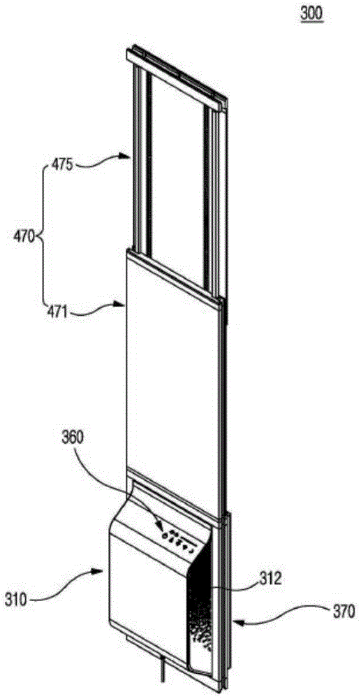
图1是示出根据本发明的优选实施例的窗户安装型智能换气净化器的立体图。FIG. 1 is a perspective view showing a window-mounted smart ventilation purifier according to a preferred embodiment of the present invention.
图2是示出根据本发明的优选实施例的窗户安装型智能换气净化器的后视图。FIG. 2 is a rear view showing a window-mounted smart ventilation purifier according to a preferred embodiment of the present invention.
图3是示出根据本发明的优选实施例的窗户安装型智能换气净化器中的弹簧减震器的动作关系的分解立体图。Fig. 3 is an exploded perspective view showing the action relationship of the spring and shock absorber in the window-mounted intelligent ventilation purifier according to the preferred embodiment of the present invention.
图4是示出根据本发明的优选实施例的窗户安装型智能换气净化器的内部构成图。FIG. 4 is a diagram showing an internal configuration of a window-mounted smart ventilation purifier according to a preferred embodiment of the present invention.
图5是示出根据本发明的优选实施例的窗户安装型智能换气净化器中的结合单元的立体图。FIG. 5 is a perspective view illustrating a combination unit in a window-installed smart ventilation purifier according to a preferred embodiment of the present invention.
图6是示出根据本发明的优选实施例的窗户安装型智能换气净化器中的结合单元的停止件和结合件的构成的分解立体图。FIG. 6 is an exploded perspective view illustrating the constitution of a stopper and a coupling unit of a coupling unit in a window-mounted smart ventilation cleaner according to a preferred embodiment of the present invention.
图7是示出根据本发明的优选实施例的窗户安装型智能换气净化器中的壳体单元和结合单元的连接状态的图。FIG. 7 is a diagram illustrating a connection state of a housing unit and a coupling unit in a window-mounted smart ventilation cleaner according to a preferred embodiment of the present invention.
图8是示出根据本发明的优选实施例的窗户安装型智能换气净化器的工作状态的内部构成图。FIG. 8 is an internal configuration diagram showing the working state of the window-mounted smart ventilation purifier according to the preferred embodiment of the present invention.
图9a是示出根据本发明的优选实施例的窗户安装型智能换气净化器中的控制部的设定画面的图,图9b及图9c是示出通过根据本发明的优选实施例的窗户安装型智能换气净化器中的控制部而实现的IOT功能的设定画面。Fig. 9a is a diagram showing the setting screen of the control unit in the window-mounted intelligent ventilation purifier according to a preferred embodiment of the present invention, and Fig. 9b and Fig. The setting screen of the IOT function realized by installing the control unit in the smart ventilation purifier.
图10a及图10b是示出根据本发明的优选实施例的窗户安装型智能换气净化器的窗框设置状态的主视图。Fig. 10a and Fig. 10b are front views showing a window frame setting state of a window-mounted smart ventilation purifier according to a preferred embodiment of the present invention.
图11是示出根据本发明的优选实施例的窗户安装型智能换气净化器的正面状态分解立体图。FIG. 11 is an exploded perspective view showing a front state of a window-mounted smart ventilation purifier according to a preferred embodiment of the present invention.
图12是示出根据本发明的优选实施例的窗户安装型智能换气净化器的背面状态分解立体图。FIG. 12 is an exploded perspective view showing a rear state of a window-mounted smart ventilation purifier according to a preferred embodiment of the present invention.
图13a及图13b是示出根据本发明的优选实施例的窗户安装型智能换气净化器中的滑动壁的要部截面图。Fig. 13a and Fig. 13b are main part sectional views showing the sliding wall in the window-mounted smart ventilation purifier according to the preferred embodiment of the present invention.
图14是示出根据本发明的优选实施例的窗户安装型智能换气净化器中的滑动壁的另一个实施例的图。FIG. 14 is a diagram illustrating another embodiment of a sliding wall in a window-mounted smart ventilation purifier according to a preferred embodiment of the present invention.
图15是例示地示出在根据本发明的优选实施例的窗户安装型智能换气净化器中适用UV-C LED(紫外线-C发光二极管,Ultraviolet-C Light Emitting Diode)的情况的图。FIG. 15 is a diagram schematically showing a case where UV-C LED (Ultraviolet-C Light Emitting Diode, Ultraviolet-C Light Emitting Diode) is applied to a window-mounted smart ventilation cleaner according to a preferred embodiment of the present invention.
图16是示例了根据本发明的优选实施例的窗户安装型智能换气净化器中的用于管理消耗品,例如过滤器、全热交换器等的用户UI画面的图。16 is a diagram illustrating a user UI screen for managing consumables, such as filters, total heat exchangers, etc., in the window-mounted smart ventilation purifier according to a preferred embodiment of the present invention.
图17是示例了根据本发明的优选实施例的窗户安装型智能换气净化器中的用于添加预约的用户UI画面的图。FIG. 17 is a diagram illustrating a user UI screen for adding a reservation in the window-mounted smart ventilation cleaner according to a preferred embodiment of the present invention.
标号说明Label description
310:壳体单元 311:室内空气排气空间310: Housing unit 311: Room air exhaust space
312:室内空气吸入口 314:室外空气引入空间312: Indoor air intake port 314: Outdoor air introduction space
315:室外空气吸入口 316:室外空气的室内引入空间315: Outdoor air intake port 316: Indoor introduction space for outdoor air
317:净化空气排放口 319:室内空气引入空间317: Purified air discharge port 319: Indoor air introduction space
320:第一空气循环单元 321:第一空气循环扇320: 1st air circulation unit 321: 1st air circulation fan
330:第二空气循环单元 331:第二空气循环扇330: Second air circulation unit 331: Second air circulation fan
340:空气净化单元 350:全热交换器340: Air purification unit 350: Total heat exchanger
360:控制部 370:结合单元360: Control Unit 370: Binding Unit
371:框架体 373:第一连接槽371: frame body 373: first connection groove
373a:马海毛 374:滚轴373a: Mohair 374: Roller
375:滑动槽 380:弹簧减震器375: slide groove 380: spring damper
470:滑动壁 471:下板470: sliding wall 471: lower plate
472:导向槽 473:插入凸起472: Guide groove 473: Insertion protrusion
474:第二连接槽 475:上板474: Second connection slot 475: Upper plate
476:导向凸起 477:紧贴片476: guide protrusion 477: close-fitting piece
478:第三连接槽 570:停止件478: Third connecting groove 570: Stop piece
670:结合件 700:锁定装置670: Joint 700: Locking device
P1:第一预滤器 P2:第二预滤器P1: 1st prefilter P2: 2nd prefilter
P3:高效微粒空气过滤器+除臭过滤器P3: High efficiency particulate air filter + deodorizing filter
具体实施方式detailed description
本说明书及权利要求书中使用的术语或者单词不应限定解释为通常的或者字典上的含义,为了通过最佳的方法来说明自身的发明,发明仅应立足于可适当地定义术语的概念的原则解释为符合本发明的技术思想的含义和概念。The terms or words used in this specification and claims should not be construed as ordinary or dictionary meanings. In order to describe the invention in the best way, the invention should only be based on the concepts that can properly define the terms. Principles are interpreted as meanings and concepts consistent with the technical idea of the present invention.
由此,本说明书中记载的实施例和图中所示的构成只不过是本发明的最优选的一个实施例,并非代表本发明的所有技术思想,因此应理解在提交本申请时可能有能够代替这些的其他均等物和变形例。Therefore, the embodiment described in this description and the structure shown in the figure are only the most preferred embodiment of the present invention, and do not represent all technical ideas of the present invention, so it should be understood that there may be possible problems when filing this application. Other equivalents and modifications in place of these.
以下,参照附图对根据本发明的优选实施例的窗户安装型智能净化换气系统进行详细说明。Hereinafter, a window-installed intelligent purification and ventilation system according to a preferred embodiment of the present invention will be described in detail with reference to the accompanying drawings.
图1是示出根据本发明的优选实施例的窗户安装型智能换气净化器的立体图,图2是示出根据本发明的优选实施例的窗户安装型智能换气净化器的后视图,图3是示出根据本发明的优选实施例的窗户安装型智能换气净化器中的弹簧减震器的动作关系的分解立体图,图4是示出根据本发明的优选实施例的窗户安装型智能换气净化器的内部构成图,图5是示出根据本发明的优选实施例的窗户安装型智能换气净化器中的结合单元的立体图,图6是示出根据本发明的优选实施例的窗户安装型智能换气净化器中的结合单元的停止件和结合件的构成的分解立体图,图7是示出根据本发明的优选实施例的窗户安装型智能换气净化器中的壳体单元和结合单元的连接状态的图。Fig. 1 is a perspective view showing a window-mounted intelligent air purifier according to a preferred embodiment of the present invention, and Fig. 2 is a rear view showing a window-mounted type intelligent air purifier according to a preferred embodiment of the present invention, Fig. 3 is an exploded perspective view showing the action relationship of the spring shock absorber in the window-mounted smart ventilation purifier according to a preferred embodiment of the present invention, and FIG. The internal composition diagram of the air purifier, Fig. 5 is a perspective view showing the combination unit in the window-mounted intelligent air purifier according to a preferred embodiment of the present invention, and Fig. 6 is a perspective view showing a combination unit according to a preferred embodiment of the present invention An exploded perspective view of the composition of the stopper and the combination of the combination unit in the window-mounted smart air purifier. FIG. 7 shows the housing unit in the window-mounted smart air purifier according to a preferred embodiment of the present invention and a diagram of the connection state of the binding unit.
参照图1至图7,根据本发明的优选实施例的窗户安装型智能换气净化器300包括壳体单元310、第一空气循环单元320、第二空气循环单元330、空气净化单元340、全热交换器350、控制部360、结合单元370。Referring to Fig. 1 to Fig. 7, according to the preferred embodiment of the present invention, the window-mounted
壳体单元310是执行供室内空气及室外空气移动的通道作用的构成装置。The
此时,壳体单元310以使空气可自由移动的形式被划分为室内空气排气空间311、室外空气引入空间314、室外空气的室内引入空间316、安装空间318及室内空气引入空间319。At this time, the
此外,壳体单元310因为冷空气和热空气通过其内部交叉移动,所以可能产生结露现象。因此,为了能够防止这样的结露现象,本发明的窗户安装型智能换气净化器300将壳体单元310的材质设计为隔热性优秀的EPP(发泡聚丙烯,Expanded Polypropylene)材质。In addition, the
在室内空气排气空间311形成有室内空气排出口313,在室内空气引入空间319形成有室内空气吸入口312,在室外空气引入空间314设置有室外空气吸入口315,在室外空气的室内引入空间316形成有净化空气排放口317。An indoor
此时,在安装空间318以使得室内空气和室外空气通过不同的管道交叉通过的形式形成。At this time, the installation space 318 is formed in such a manner that indoor air and outdoor air cross each other through different ducts.
另外,第一空气循环单元320设置于室内空气排气空间311,为了向外部排出室内污染的空气,执行使得空气强制循环的作用。In addition, the first
换句话说,第一空气循环单元320包括第一空气循环扇321,其在供给外部电源时使得空气强制循环,此时,为了能够将通过室内空气吸入口312流入的污染的室内空气向室内空气排出口312侧移动,第一空气循环扇321使得空气强制循环。In other words, the first
另外,第二空气循环单元330设置于室外空气的室内引入空间316,执行使得空气强制循环的作用,以便能够使得室外空气流入室内。In addition, the second
换句话说,第二空气循环单元330包括第二空气循环扇331,其在供给外部电源时使得空气强制循环,此时,为了能够将通过室外空气吸入口315流入的室外空气向室外空气的室内引入空间316侧移动,第二空气循环扇331执行使得空气强制循环的作用。In other words, the second
另外,空气净化单元340执行对通过室内空气吸入口312流入的室内空气中所含有的杂质和通过室外空气吸入口315流入的室外空气中所含有的杂质进行过滤并净化的作用。In addition, the
此时,空气净化单元340设置于室内空气和室外空气的移动路径,执行过滤杂质的作用,本发明的优选实施例包括设置于室内空气引入空间319和安装空间318之间的第一预滤器P1、设置于室外空气引入空间314和安装空间318之间的第二预滤器P2、高效微粒空气过滤器P3。At this time, the
另外,全热交换器350设置于在壳体单元310设置的安装空间318。In addition, the
换句话说,就如通过附图可确认的一样,室内空气和室外空气通过不同的管道交叉通过安装空间318。因此,全热交换器350由于室内空气和室外空气彼此在管道上接触,因而实现热交换。In other words, as can be confirmed from the drawings, indoor air and outdoor air cross through the installation space 318 through different ducts. Accordingly, the
换句话说,当室内空气温暖而室外空气凉的时候,温暖的室内空气的热传递至室外空气,从而将流入室内的空气变暖,当室内空气凉而室外空气温暖的时候,室内空气的低温度传递至室外空气,从而使得流入室内的空气凉爽。In other words, when the indoor air is warm and the outdoor air is cool, the heat of the warm indoor air is transferred to the outdoor air, thereby warming the air flowing into the room, and when the indoor air is cool and the outdoor air is warm, the low temperature of the indoor air The temperature is transferred to the outside air, which cools the air flowing into the room.
因此,全热交换器350可通过向室内供给的室外空气的温度调节在根据本发明的优选实施例的智能换气净化器300的工作过程中将热损失最小化。Therefore, the
另外,控制部360设置于壳体单元310的前面,执行对根据本发明的优选实施例的智能换气净化器300的打开/关闭(ON/OFF)功能及对第一空气循环单元320和第二空气循环单元330的动作进行控制的作用。In addition, the
此外,在控制部360设置有另外的计时器T。因此,控制部360还可以体现告知何时更换高效微粒空气过滤器+除臭过滤器P3的过滤器更换提醒功能及计时器复位功能。In addition, another timer T is provided in the
此外,根据实施例,在控制部360还可以追加告知全热交换器350的更换的提醒及计时器功能。In addition, according to an embodiment, a reminder and a timer function for notifying replacement of the
此外,向控制部360供给信号的传感器模块包括VOC传感器P1和CO2传感器P2及微尘传感器P3。In addition, the sensor module that supplies a signal to the
因此,根据本发明的优选实施例的窗户安装型智能换气净化器可通过传感器确认室外空气的质量及室内空气的质量。Therefore, the window-mounted smart ventilator according to a preferred embodiment of the present invention can confirm the quality of outdoor air and the quality of indoor air through sensors.
此外,控制部360附加有通过网络和智能设备收发数据的IOT功能,从而用户可以通过智能设备确认各种信息(室外温度/湿度、室外综合空气质量、室外空气质量、室内综合空气质量、室内空气质量、远程控制及过滤器更换时期)。In addition, the
室外空气吸入口315还设置有弹簧减震器380,其在空气循环时开放室外空气吸入口315,在空气循环停止时关闭室外空气吸入口315。The outdoor
此时,弹簧减震器38显示如下动作关系:当通过VOC传感器N1的动作判断室外空气有问题(烟味、火烟、臭味)并且控制部360使得第二空气循环单元330的动作停止时,空气的流动停止的同时,弹簧减震器380关闭室外空气吸入口315,当通过VOC传感器N1的动作判断室外空气没有问题并且控制部360使得第二空气循环单元330工作时,通过循环的空气的流动过程中产生的力使得室外空气吸入口315开放。At this time, the spring shock absorber 38 shows the following action relationship: when it is judged by the action of the VOC sensor N1 that there is a problem with the outdoor air (smoke, fire smoke, odor) and the
另外,结合单元370是执行用于将壳体单元310固定于窗框和窗户之间的作用的构成装置。In addition, the combining
此时,结合单元370包括框架体371和滑动壁470。At this time, the combining
框架体371为向上方开口的格子形状,在外面形成有第一连接槽373,以便能够连接于窗框的轨道,在底面,在第一连接槽373的内侧形成有在窗框的轨道赋予滚动力的滚轴374,内面设置有滑动槽375,上端形成有插入孔377,其中,壳体单元310的边缘部位插入连接于滑动槽375。The
此时,在第一连接槽373还可包括马海毛373a,其用于切断外面的风通过一般的窗框等间隙吹进或者切断灰尘等异物的进入。At this time, the first connecting
此外,滑动壁470结合于壳体单元310的上端,起到对从壳体单元310的上端至窗框的上部进行收尾的作用。In addition, the sliding
因此,对滑动壁470的具体结构进行观察,滑动壁470包括下板471、上板475、停止件570及结合件670。Therefore, observing the specific structure of the sliding
下板471紧固连接于壳体单元310的上端,内侧形成有导向槽472,下端凸出地形成有插入凸起473,两侧设置有与窗框的轨道相连接的第二连接槽474,上端形成有固定孔H。The
此时,插入凸起473插入及连接于框架体371的插入孔377,从而框架体371和下板471具有牢固的连接关系。At this time, the
此外,上板475以可滑动移动的形式连接于下板471,外面形成有以可滑动移动的形式连接于导向槽472的导向凸起476,两侧设置有紧贴片477,为了沿着下板471实现稳定的滑动动作,使得紧贴片477与下板471的边缘部接触,上端两侧设置有与窗框的轨道相连接的第三连接槽478。In addition, the
因此,当导向凸起476沿着导向槽472滑动移动时,紧贴片477紧贴于下板471的后面,从而上板475可实现更加稳定的滑动移动动作。Therefore, when the
此外,停止件570设置于下板471和上板475之间,当通过上板475的滑动移动使得发生改变的下板471和上板475的可变调节长度达到用户想要的长度时,限制上板475的滑动动作。In addition, the
此时,停止件570包括楔形限位器571和限位器轨道574。At this time, the
楔形限位器571设置于下板471的后面,具有通过弹性弹簧572的弹性力向上板475侧凸出的动作关系。The wedge-shaped
此外,限位器轨道574形成于上板(475)的前面,以交替的形式连续形成有楔形的槽和凸起,以便能够卡住连接于楔形限位器(571)。In addition, stopper rails 574 are formed on the front of the upper plate (475), and are continuously formed with wedge-shaped grooves and protrusions in an alternating manner so as to be clamped and connected to the wedge-shaped stopper (571).
因此,楔形限位器571插入于限位器轨道574的楔形槽,限制下板471和上板475的长度变化,如果用户向上方拉拽上板475,则借助于该外力,楔形限位器571沿着限位器轨道574移动。Therefore, the wedge-shaped
之后,如果解除向上板475作用的外力,则楔形限位器571插入限位器轨道574的楔形槽,限制下板471和上板475的长度变化。Afterwards, if the external force acting on the
另外,结合件670是执行将下板471和上板475结合的作用的构成装置。此时,结合件670紧固连接于固定孔H,其端部对导向凸起476进行加压,执行将下板471和上板475结合的作用。In addition, the
图8是示出根据本发明的优选实施例的窗户安装型智能换气净化器的动作状态的内部构成图。Fig. 8 is an internal configuration diagram showing the operating state of the window-mounted smart ventilation cleaner according to a preferred embodiment of the present invention.
参照图8,通过“打开”控制部360而使得根据本发明的优选实施例的智能换气净化器300工作。Referring to FIG. 8 , the
此时,当根据本发明的优选实施例的窗户安装型智能换气净化器300工作时,第一空气循环单元320的第一空气循环扇321进行工作,将污染的室内空气向外部排出。At this time, when the window-mounted
换句话说,当第一空气循环扇321工作时,通过室内空气吸入口312流入的污染的室内空气经由室内空气吸入口312、室内空气引入空间319、安装空间318、室内空气排气空间311及室内空气排出口313向室外排出。In other words, when the first
此时,经由室内空气引入空间319向安装空间318移动的污染的室内空气通过空气净化单元340的第一预滤器P1对空气中的灰尘及异物进行过滤。At this time, the polluted indoor air moving to the installation space 318 through the indoor
此外,当第二空气循环单元330的第二空气循环扇331工作时,洁净的室外空气流入室内。In addition, when the second
换句话说,当第二空气循环扇331工作时,通过室外空气吸入口315流入的室外空气经由室外空气吸入口315、室外空气引入空间314、安装空间318、室外空气的室内引入空间316及净化空气排放口317向室内流入。In other words, when the second
此时,经由室外空气引入空间314向安装空间318移动的室外空气通过净化单元340的第二预滤器P2及高效微粒空气过滤器+除臭过滤器P3对空气中的灰尘及异物进行过滤,使净化的空气供给至室内。At this time, the outdoor air moving from the outdoor
此时,在安装空间318中室内空气和室外空气通过不同的管道交叉通过,通过设置于安装空间318的全热交换器350使得室内空气和室外空气之间进行热交换,从而可以将因向室内供给外部净化空气造成的热损失最小化。At this time, in the installation space 318, the indoor air and the outdoor air cross through different pipes, and the
另外,用户可通过设置于控制部360的计时器T容易得知高效微粒空气过滤器+除臭过滤器P3的更换时期。之后,如果用户更换了过滤器P1、P2、P3,则用户将计时器复位,从而可以让用户知道重新更换的过滤器P3的更换时期。In addition, the user can easily know the replacement time of the HEPA filter + deodorizing filter P3 through the timer T provided in the
此外,设置于控制部360的VOC传感器N1和CO2传感器N2及微尘传感器N3对室外空气的质量和室内空气的质量进行测量。In addition, the VOC sensor N1, the CO2 sensor N2, and the dust sensor N3 provided in the
因此,当通过传感器N1、N2、N3测量出室内空气的质量洁净或者室外空气的质量差时,以使得根据本发明的优选实施例的智能换气净化器300的动作停止的形式进行控制,当通过传感器N1、N2、N3测量出室内空气的质量差或者室外空气的质量良好时,以使得要进行净化的根据本发明的优选实施例的智能换气净化器300工作的形式进行控制。Therefore, when the quality of the indoor air is clean or the quality of the outdoor air is poor when the sensors N1, N2, and N3 are used to control the action of the
本发明中,根据实施例,CO2传感器N2和微尘传感器N3可安装于室内侧。In the present invention, according to an embodiment, the CO2 sensor N2 and the dust sensor N3 may be installed indoors.
此时,CO2传感器N2和微尘传感器N3根据在室内测量的CO2及微尘的污染的浓度对扇速度进行控制,从而可自动调整换气量。At this time, the CO2 sensor N2 and the fine dust sensor N3 control the fan speed based on the CO2 and fine dust pollution concentrations measured in the room, thereby automatically adjusting the ventilation rate.
例如,可以以如下形式设定:当污染严重时,扇的速度变快,换气量增加,当污染少的时候,减慢扇321、331的速度,使得换气量减少。此外,当污染非常少的时候,使得扇321、331停止,如果污染度重新上升,则再启动扇。(减少电费、冷/暖气费)For example, it can be set in the following form: when the pollution is serious, the speed of the fan becomes faster, and the ventilation volume increases; when the pollution is low, the speed of the
此外,VOC传感器N1可安装于室外侧,以便能够感知室外空气的臭味。In addition, the VOC sensor N1 may be installed on the outdoor side so as to be able to sense the odor of the outdoor air.
此时,控制部360以如下形式进行设计:如果通过VOC传感器N1感知到室外空气中有臭味,则可通过第二空气循环扇331的动作控制而切断外部臭味。At this time, the
另外,就本发明的优选实施例中所包括的弹簧减震器380而言,当通过VOC传感器N1的动作判断室外空气有问题(烟味、火烟、臭味)并且控制部360使得第二空气循环单元330的动作停止时,弹簧减震器380通过自身弹性力而关闭室外空气吸入口315,当通过VOC传感器N1的动作判断室外空气没有问题并且控制部360使得第二空气循环单元330工作时,可通过强制循环的空气的流动使得吸入口315开放。In addition, as far as the
根据本发明的优选实施例的窗户安装型智能换气净化器300的控制部360还附加有通过网络和智能设备收发数据的IOT功能。According to the preferred embodiment of the present invention, the
图9a是示出根据本发明的优选实施例的窗户安装型智能换气净化器中的控制部的设定画面的图,图9b及图9c是示出通过根据本发明的优选实施例的窗户安装型智能换气净化器中的控制部而实现的IOT功能的设定画面。Fig. 9a is a diagram showing the setting screen of the control unit in the window-mounted intelligent ventilation purifier according to a preferred embodiment of the present invention, and Fig. 9b and Fig. The setting screen of the IOT function realized by installing the control unit in the smart ventilation purifier.
参照图9a,本发明的控制部360可以用室内控制质量显示画面、就寝模式设定画面、无线网显示画面、扇显示画面、人工智能显示画面及电源显示换面来表示。Referring to FIG. 9a, the
此外,根据图9b及图9c,就根据本发明的优选实施例的窗户安装型智能换气净化器300而言,用户可通过智能设备确认各种信息(室外温度/湿度、室外综合空气质量、室外空气质量、室内综合空气质量、室内空气质量、远程控制及过滤器更换时期),此外,可控制智能换气净化器300的动作。In addition, according to FIG. 9b and FIG. 9c, as far as the window-mounted
在此,IOT功能的具体的工作原理通常是众所周知的公知通用的技术,省略对此的详细说明。Here, the specific working principle of the IOT function is usually a well-known and commonly used technology, and a detailed description thereof is omitted.
另外,参照附图对用于设置于窗框30的结合单元370的设置状态进行详细说明。In addition, an installation state of the
图10a及图10b是示出根据本发明的优选实施例的窗户安装型智能换气净化器的窗框设置状态的主视图,图11是示出根据本发明的优选实施例的窗户安装型智能换气净化器的正面状态分解立体图,图12是示出根据本发明的优选实施例的窗户安装型智能换气净化器的背面状态分解立体图,图13a及图13b是示出根据本发明的优选实施例的窗户安装型智能换气净化器中的滑动壁的要部截面图。Figure 10a and Figure 10b are front views showing the window frame setting state of the window-mounted smart air purifier according to a preferred embodiment of the present invention. The exploded perspective view of the front state of the air purifier, Fig. 12 is an exploded perspective view of the back state of the window-mounted intelligent air purifier according to a preferred embodiment of the present invention, and Fig. 13a and Fig. 13b show the preferred embodiment of the present invention. A cross-sectional view of the main part of the sliding wall in the window-mounted smart ventilation cleaner of the embodiment.
参照图10a及图10b和图11、图12、图13a、图13b,为了将根据本发明的优选实施例的窗户安装型智能换气净化器300设置于窗框30,首先,将结合单元370的框架体371安装在用于设置根据本发明的优选实施例的智能换气净化器300的窗框30和窗户31之间的间隙。Referring to Fig. 10a and Fig. 10b and Fig. 11, Fig. 12, Fig. 13a, Fig. 13b, in order to install the window-mounted
此时,如此结合的框架体371通过形成于其周围的第一连接槽373与窗框30的轨道(省略示出)相结合,在框架体371的底面,滚轴374安装于轨道,从而可通过滚动力进行左右调节。At this time, the
之后,将壳体单元310插入结合于框架体371的滑动槽375即可。Afterwards, the
之后,将构成滑动壁470的下板471的下端连接于壳体单元310的上端。After that, the lower end of the
之后,将上板475的导向凸起476连接于下板471的导向槽472。Afterwards, the
之后,通过使得上板475滑动移动而进行可变调节,以便滑动壁470整体的长度成为用户想要的长度。After that, variable adjustment is performed by slidingly moving the
之后,当滑动壁470达到用户想要的长度时,停止件570限制上板475和下板471的长度变化。Afterwards, when the sliding
换句话说,滑动壁470的楔形限位器571插入限位器轨道574的楔形槽,限制下板471和上板475的长度变化,如果用户向上方拉拽上板475,则借助于该外力,楔形限位器571沿着限位器轨道574移动。In other words, the wedge-shaped
之后,如果解除向上板475作用的外力,则楔形限位器571插入限位器轨道574的楔形槽,限制下板471和上板475的长度变化。Afterwards, if the external force acting on the
在此状态下,通过结合件670将下板471和上板475结合。换句话说,当通过停止件570使得滑动壁470成为用户想要的长度时,结合件670紧固连接于固定孔H,其端部对导向凸起476进行加压,从而将下板471和上板475结合。In this state, the
另外,本发明的实施例中,对框架体371和下板471和上板475的依次的结合设置进行了说明,并非限定于此,当然可根据作业环境以事先组装的状态安装于窗框30。In addition, in the embodiment of the present invention, the sequential combination of the
换句话说,根据本发明的优选实施例的智能换气净化器在内部设置有另外的全热交换器,可事先防止在换气过程中可能产生的热损失,减少供暖费或者制冷费。In other words, the intelligent ventilation purifier according to the preferred embodiment of the present invention is equipped with another total heat exchanger inside, which can prevent possible heat loss during the ventilation process in advance, and reduce heating or cooling costs.
此外,就根据本发明的优选实施例的智能换气净化器而言,在施工过程中,无需墙体上穿孔也可以设置于窗框,从而可以提高施工及设置工艺的便利性。In addition, as far as the intelligent ventilation purifier according to the preferred embodiment of the present invention is concerned, it can be installed on the window frame without perforating the wall during the construction process, thereby improving the convenience of the construction and installation process.
图14是示出根据本发明的优选实施例的窗户安装型智能换气净化器中的滑动壁的另一个实施例的图。FIG. 14 is a diagram illustrating another embodiment of a sliding wall in a window-mounted smart ventilation purifier according to a preferred embodiment of the present invention.
参照图14,在下板471的上端还设置有沿着导向凸起476升降移动的锁定装置700。Referring to FIG. 14 , the upper end of the
此时,当锁定装置700位于下板471的上端时,对楔形限位器571进行支撑,防止楔形限位器571向后移动。At this time, when the
因此,楔形限位器571固定于限位器轨道574的楔形形状的槽,从而下板471具有稳定的固定结构。Therefore, the wedge-shaped
另外,图15是例示地示出在根据本发明的优选实施例的窗户安装型智能换气净化器中适用UV-C LED(紫外线-C发光二极管,Ultraviolet-C Light Emitting Diode)的情况的图。In addition, FIG. 15 is a diagram illustrating a situation in which UV-C LED (ultraviolet-C light emitting diode, Ultraviolet-C Light Emitting Diode) is applied to a window-mounted smart ventilation cleaner according to a preferred embodiment of the present invention. .
根据本发明的实施例的UV-C LED可设置于窗户安装型智能换气净化器的安装空间318,例如与全热交换器350邻近的区域。The UV-C LED according to the embodiment of the present invention can be installed in the installation space 318 of the window-mounted smart air purifier, such as the area adjacent to the
UV-C是一种具有100nm至280nm的较短波长区域的紫外线,将这样的具有短波长特性的UV-C LED设置于换气净化器内,可从根本上对室内空气中产生的细菌进行杀菌处理。UV-C is a kind of ultraviolet light with a relatively short wavelength range from 100nm to 280nm. Installing such a UV-C LED with short wavelength characteristics in the air purifier can fundamentally eliminate bacteria generated in the indoor air. Sterilization treatment.
另外,图16是示例了根据本发明的优选实施例的窗户安装型智能换气净化器中的用于管理消耗品,例如过滤器、全热交换器等的用户UI(用户界面,User Interface)画面的图。In addition, FIG. 16 illustrates a user UI (User Interface, User Interface) for managing consumables, such as filters, total heat exchangers, etc., in a window-mounted smart ventilation purifier according to a preferred embodiment of the present invention. picture of the screen.
各个消耗品可以用数值来显示到目前为止的使用时间、剩余时间、更换周期等,也可以用图表来显示,以便可以让用户直观地了解使用时间及剩余时间。For each consumable, the usage time up to now, remaining time, replacement cycle, etc. can be displayed numerically or graphically so that the user can intuitively understand the usage time and remaining time.
图17是示例了根据本发明的优选实施例的窗户安装型智能换气净化器中的用于添加预约的用户UI画面的图。FIG. 17 is a diagram illustrating a user UI screen for adding a reservation in the window-mounted smart ventilation cleaner according to a preferred embodiment of the present invention.
在预约添加画面可设定开始时间、结束时间、每周重复与否等,可调节各种扇的各阶段的强度。In the appointment adding screen, you can set the start time, end time, repeat every week, etc., and adjust the intensity of each stage of each fan.
Claims (2)
Applications Claiming Priority (2)
| Application Number | Priority Date | Filing Date | Title |
|---|---|---|---|
| KR10-2020-0041474 | 2020-04-06 | ||
| KR1020200041474A KR102188972B1 (en) | 2020-04-06 | 2020-04-06 | Window mounted Smart Clean Ventilation purifier |
Publications (2)
| Publication Number | Publication Date |
|---|---|
| CN113494750A CN113494750A (en) | 2021-10-12 |
| CN113494750B true CN113494750B (en) | 2022-12-20 |
Family
ID=73790397
Family Applications (1)
| Application Number | Title | Priority Date | Filing Date |
|---|---|---|---|
| CN202110348301.3A Expired - Fee Related CN113494750B (en) | 2020-04-06 | 2021-03-31 | Window installation type intelligent air-changing purifier |
Country Status (5)
| Country | Link |
|---|---|
| US (1) | US11913652B2 (en) |
| EP (1) | EP3913293B1 (en) |
| KR (1) | KR102188972B1 (en) |
| CN (1) | CN113494750B (en) |
| WO (1) | WO2021206292A1 (en) |
Families Citing this family (17)
| Publication number | Priority date | Publication date | Assignee | Title |
|---|---|---|---|---|
| CN108548238A (en) * | 2018-06-13 | 2018-09-18 | 中国矿业大学 | Window type air cleaning system |
| KR102188972B1 (en) * | 2020-04-06 | 2020-12-10 | 원태연 | Window mounted Smart Clean Ventilation purifier |
| KR102377857B1 (en) * | 2021-03-17 | 2022-03-24 | (주)바이오트코리아 | non-face-to-face specimens collecting device with adjustable height |
| CN113685931A (en) * | 2021-07-30 | 2021-11-23 | 河南舒岚环保科技有限公司 | Window type fresh air fan and method facilitating later-stage cleaning of internal accumulated dust |
| CN114279024B (en) * | 2021-12-31 | 2024-02-13 | 深圳英创能源环境技术有限公司 | Fresh air purifying all-in-one machine |
| KR20230126085A (en) * | 2022-02-22 | 2023-08-29 | 삼성전자주식회사 | Air cleaner and method for controlling the air cleaner |
| CN114487309B (en) * | 2022-04-18 | 2022-06-21 | 南通森呼吸环保科技有限公司 | Distributed indoor air detection device and method based on wireless transmission |
| USD1042770S1 (en) * | 2022-05-13 | 2024-09-17 | Lg Electronics Inc. | Frame for window air conditioner |
| BE1030553B1 (en) * | 2022-05-23 | 2023-12-18 | Renson Ventilation Nv | A ventilation system for a residential building |
| KR102524895B1 (en) * | 2022-05-26 | 2023-04-26 | 주식회사 서정 | Automatic ventilation window |
| KR102679636B1 (en) | 2022-06-21 | 2024-06-27 | 윤영상 | Window type air cleaner |
| WO2024042658A1 (en) * | 2022-08-24 | 2024-02-29 | 三菱電機株式会社 | Ventilation system |
| JP2024110707A (en) * | 2023-02-03 | 2024-08-16 | 三菱電機株式会社 | Air purifier, mobile terminal and air purification system |
| WO2024219621A1 (en) * | 2023-04-20 | 2024-10-24 | 삼성전자주식회사 | Mounting device and air conditioning apparatus including same |
| CN117060136B (en) * | 2023-08-21 | 2024-08-30 | 广东浩博特科技股份有限公司 | Intelligent socket capable of counting electricity consumption |
| CN118179197B (en) * | 2024-04-29 | 2025-01-03 | 唐山亨坤新能源材料有限公司 | An environmentally friendly tail gas purification device for lithium iron manganese phosphate processing |
| CN122384200A (en) * | 2025-01-14 | 2026-07-14 | 研能科技股份有限公司 | Intelligent networking fresh air cleaner |
Citations (5)
| Publication number | Priority date | Publication date | Assignee | Title |
|---|---|---|---|---|
| CN105134049A (en) * | 2015-09-04 | 2015-12-09 | 周国增 | Window frame with air purification function |
| CN205191775U (en) * | 2015-12-11 | 2016-04-27 | 四川长虹空调有限公司 | Intelligent air purifier who possesses control filter screen cleanliness factor function |
| CN206468252U (en) * | 2016-10-24 | 2017-09-05 | 利桑公司 | Window ventilating system with heat exchange and air-cleaning function |
| CN107152744A (en) * | 2016-03-03 | 2017-09-12 | 庆东纳碧安株式会社 | Air interchanger |
| KR20190113516A (en) * | 2018-03-28 | 2019-10-08 | 김우진 | Ventilation system for window frames |
Family Cites Families (54)
| Publication number | Priority date | Publication date | Assignee | Title |
|---|---|---|---|---|
| US1153067A (en) * | 1915-02-15 | 1915-09-07 | Leslie S Hackney | Ventilating device. |
| US2010808A (en) * | 1933-04-01 | 1935-08-13 | Daniel L Braine | Air conditioner |
| US2036851A (en) * | 1934-02-12 | 1936-04-07 | Edwin F Chittenden | Window ventilator |
| US2218330A (en) * | 1939-01-10 | 1940-10-15 | Bell Telephone Labor Inc | Ventilator |
| US2337325A (en) * | 1941-01-10 | 1943-12-21 | Gen Electric | Air circulating device |
| US2373497A (en) * | 1941-09-08 | 1945-04-10 | Philco Radio & Television Corp | Ventilator |
| US2559495A (en) * | 1947-12-08 | 1951-07-03 | Calkins Robert Walter | Portable air controller |
| US3158083A (en) * | 1961-03-10 | 1964-11-24 | American Air Filter Co | Bypass damper construction |
| US3120340A (en) * | 1961-12-01 | 1964-02-04 | Winton C Strumpell | Blower |
| DE1901361B2 (en) * | 1968-01-29 | 1972-09-14 | Baumann, Ludwig, Niederhelfenschwil, St. Gallen (Schweiz) | ROOM FAN WITH SIMULTANEOUS PROMOTION OF DRAIN AND EXHAUST AIR, IN PARTICULAR WITH SHUT-OFF RODS FOR BOTH AIR FLOWS |
| US4043141A (en) * | 1976-02-26 | 1977-08-23 | A. C. Manufacturing Company | Air conditioning method and apparatus with humidifier |
| US4458745A (en) * | 1979-02-02 | 1984-07-10 | Josef Gartner & Co. | Device for controlling the temperature of rooms in a building |
| US4460388A (en) * | 1981-07-17 | 1984-07-17 | Nippon Soken, Inc. | Total heat exchanger |
| US5238052A (en) * | 1989-08-17 | 1993-08-24 | Stirling Technology, Inc. | Air to air recouperator |
| US5660605A (en) * | 1995-09-18 | 1997-08-26 | Holmes Products Corp. | Window fan |
| US5660586A (en) * | 1995-09-22 | 1997-08-26 | Duracraft Corporation | Variable discharge window fan |
| US5730651A (en) * | 1996-08-08 | 1998-03-24 | Lakewood Engineering And Manufacturing Co. | Independent directional-flow air ducts for low-profile window fan |
| US5902183A (en) * | 1996-11-15 | 1999-05-11 | D'souza; Melanius | Process and apparatus for energy conservation in buildings using a computer controlled ventilation system |
| US6328095B1 (en) * | 2000-03-06 | 2001-12-11 | Honeywell International Inc. | Heat recovery ventilator with make-up air capability |
| US6494940B1 (en) * | 2000-09-29 | 2002-12-17 | Hamilton Beach/Proctor-Silex, Inc. | Air purifier |
| JP3654349B2 (en) | 2001-07-09 | 2005-06-02 | ソニー株式会社 | Content preference calculation method and content receiving device |
| NL1020481C1 (en) * | 2002-04-26 | 2003-10-31 | Oxycell Holding Bv | Enthalpy exchanger, designed as a frame style. |
| US6800022B2 (en) * | 2003-02-19 | 2004-10-05 | Delphi Technologies, Inc. | Inlet air control method for a vehicle HVAC system having an air quality sensor |
| EP1486637B1 (en) * | 2003-06-12 | 2009-08-05 | Lidartech Co., Ltd. | Window having a ventilation equipment |
| ES2245875B1 (en) * | 2004-03-26 | 2006-11-16 | Joaquin Espuelas Peñalva | MANUFACTURING AND FILTER PROCESS OF NON-WOVEN FABRIC AND / OR FILTERING INJECTED SHEETS OR STRUCTURES OBTAINED BY SUCH PROCESS FOR FILTRATION AND ELIMINATION OF THE PNEUMOFILA LEGIONELLA. |
| KR100714719B1 (en) * | 2004-12-03 | 2007-05-04 | 삼성전자주식회사 | Methods and devices for cleaning air while moving |
| US7311740B2 (en) * | 2005-02-14 | 2007-12-25 | Honeywell International, Inc. | Snap acting split flapper valve |
| KR100617080B1 (en) * | 2005-02-15 | 2006-08-30 | 엘지전자 주식회사 | Air Conditioning System and Its Control Method |
| KR100728339B1 (en) * | 2005-12-09 | 2007-06-13 | 주식회사 대우일렉트로닉스 | Waste Heat Recovery Ventilator |
| US7966837B2 (en) * | 2007-03-28 | 2011-06-28 | Madina, LLC | Air-conditioning register assembly and method |
| CA2602737A1 (en) * | 2007-09-14 | 2009-03-14 | Air Tech Equipment Ltd. | Dehumidifying system |
| US8155797B2 (en) * | 2009-08-12 | 2012-04-10 | James Wiese | Window fan control system and method of controlling a fan unit |
| US8123142B2 (en) * | 2009-08-20 | 2012-02-28 | Cislo Daniel M | Solar powered smart ventilation system |
| JP5999353B2 (en) * | 2012-12-10 | 2016-09-28 | パナソニックIpマネジメント株式会社 | Air conditioning control system |
| CN105182785B (en) * | 2015-09-30 | 2018-05-25 | 北京格瑞那环能技术有限责任公司 | A kind of intelligent domestic system |
| KR101778736B1 (en) * | 2016-09-29 | 2017-09-14 | 주식회사 미지에너텍 | Control method for air cleaner and apparatus therefor |
| CN206531233U (en) * | 2017-02-17 | 2017-09-29 | 银成化学株式会社 | Ground heat recovery ventilation device |
| KR101812447B1 (en) * | 2017-04-14 | 2017-12-26 | 윤병석 | Ventilation Device |
| KR101828587B1 (en) * | 2017-06-26 | 2018-02-13 | (주)센도리 | Ventilator to remove dust |
| KR101939686B1 (en) * | 2017-06-30 | 2019-04-12 | 주식회사 현대엘앤씨 | Mechanical ventilation control system of integrated windows using IoT |
| CN107401800A (en) * | 2017-07-17 | 2017-11-28 | 深圳沃海森科技有限公司 | The environmental-protection energy-saving air-conditioning system being arranged on new blower fan |
| WO2019081651A1 (en) * | 2017-10-26 | 2019-05-02 | Koninklijke Philips N.V. | Smart air purification |
| KR102022616B1 (en) * | 2017-11-30 | 2019-11-26 | 배진수 | Method and device for window-mounted air-cleaner |
| KR102052638B1 (en) * | 2018-01-29 | 2019-12-05 | 이윤미 | Duct type multifunction air cleaner and operation method thereof |
| KR101965770B1 (en) * | 2018-02-06 | 2019-04-04 | 김우진 | Ventilation system for window frames |
| CN108534333A (en) * | 2018-03-16 | 2018-09-14 | 青岛海尔空调器有限总公司 | Heat exchanger core for two-way in/out air tube |
| CN108361874A (en) * | 2018-03-23 | 2018-08-03 | 上海交通大学 | Heat exchange fresh air purifier |
| KR20190117897A (en) * | 2018-04-09 | 2019-10-17 | 박준흥 | Air Purifier Combined with Ventilation |
| CN108917081A (en) * | 2018-05-31 | 2018-11-30 | 安徽科清净化科技有限公司 | A kind of new blower of novel building ventilation |
| KR102203801B1 (en) * | 2018-06-15 | 2021-01-18 | (주)공존에스앤티 | Window-type smart air purifying ventilator |
| KR101956632B1 (en) * | 2018-07-16 | 2019-03-11 | (주)센도리 | Filter of airconditioner |
| KR102039071B1 (en) * | 2019-03-26 | 2019-11-01 | 주식회사 브랜뉴인터내셔널 | Window frame air cleaner with easy installation and demounting |
| KR102060633B1 (en) * | 2019-07-24 | 2019-12-30 | 서진공조(주) | Air circulation system with air cleaning technology |
| KR102188972B1 (en) * | 2020-04-06 | 2020-12-10 | 원태연 | Window mounted Smart Clean Ventilation purifier |
-
2020
- 2020-04-06 KR KR1020200041474A patent/KR102188972B1/en active Active
-
2021
- 2021-02-26 WO PCT/KR2021/002478 patent/WO2021206292A1/en not_active Ceased
- 2021-02-26 EP EP21719016.4A patent/EP3913293B1/en active Active
- 2021-03-31 CN CN202110348301.3A patent/CN113494750B/en not_active Expired - Fee Related
- 2021-04-05 US US17/222,167 patent/US11913652B2/en active Active
Patent Citations (5)
| Publication number | Priority date | Publication date | Assignee | Title |
|---|---|---|---|---|
| CN105134049A (en) * | 2015-09-04 | 2015-12-09 | 周国增 | Window frame with air purification function |
| CN205191775U (en) * | 2015-12-11 | 2016-04-27 | 四川长虹空调有限公司 | Intelligent air purifier who possesses control filter screen cleanliness factor function |
| CN107152744A (en) * | 2016-03-03 | 2017-09-12 | 庆东纳碧安株式会社 | Air interchanger |
| CN206468252U (en) * | 2016-10-24 | 2017-09-05 | 利桑公司 | Window ventilating system with heat exchange and air-cleaning function |
| KR20190113516A (en) * | 2018-03-28 | 2019-10-08 | 김우진 | Ventilation system for window frames |
Also Published As
| Publication number | Publication date |
|---|---|
| EP3913293B1 (en) | 2024-10-02 |
| EP3913293C0 (en) | 2024-10-02 |
| US20210310671A1 (en) | 2021-10-07 |
| US11913652B2 (en) | 2024-02-27 |
| KR102188972B1 (en) | 2020-12-10 |
| EP3913293A4 (en) | 2022-03-30 |
| EP3913293A1 (en) | 2021-11-24 |
| CN113494750A (en) | 2021-10-12 |
| WO2021206292A1 (en) | 2021-10-14 |
Similar Documents
| Publication | Publication Date | Title |
|---|---|---|
| KR102188972B1 (en) | Window mounted Smart Clean Ventilation purifier | |
| CN111288583B (en) | A multifunctional fresh air purifier and operation control method | |
| KR102008625B1 (en) | Air conditioning system using outside air type fresh air unit for an affix ceiling | |
| KR100690987B1 (en) | Air cleaning system using ventilation unit | |
| CN206468252U (en) | Window ventilating system with heat exchange and air-cleaning function | |
| KR102383783B1 (en) | Energy saving air purification type ventilation system linked with weather information | |
| CN108302685B (en) | Air circulation system with internal air circulation, discharge and suction functions | |
| KR102081237B1 (en) | Ventilation and Energy Saving Air Purifier | |
| CN103335361A (en) | Air conditioner indoor machine | |
| KR102052348B1 (en) | Vantilation | |
| KR101941574B1 (en) | A heat recovery ventilator for preventing condensation | |
| KR100587359B1 (en) | Air cleaner integrated ventilation system | |
| KR100580288B1 (en) | Ventilation intake unit with sterilization and temperature control | |
| CN108386914A (en) | A kind of fresh air conditioner indoor unit | |
| CN111520839B (en) | A window-type fresh air purifier | |
| KR101884398B1 (en) | Heat recovery ventilator | |
| KR101895355B1 (en) | A ventilator for waste heat recovery | |
| KR101851676B1 (en) | A ventilator for waste heat recovery | |
| KR100587315B1 (en) | Ventilation system | |
| KR101001435B1 (en) | Bioceramic Air Purifier for Ventilation | |
| KR101851677B1 (en) | A heat recovery ventilator for preventing condensation | |
| KR200373800Y1 (en) | ventilation system for heating | |
| KR100587313B1 (en) | Air cleaner integrated ventilation system | |
| KR20200134051A (en) | Air cleaning combined use ventilator for windows mounted type | |
| KR200407836Y1 (en) | Air cleaning system using ventilation unit |
Legal Events
| Date | Code | Title | Description |
|---|---|---|---|
| PB01 | Publication | ||
| PB01 | Publication | ||
| SE01 | Entry into force of request for substantive examination | ||
| SE01 | Entry into force of request for substantive examination | ||
| GR01 | Patent grant | ||
| GR01 | Patent grant | ||
| CF01 | Termination of patent right due to non-payment of annual fee |
Granted publication date: 20221220 |
|
| CF01 | Termination of patent right due to non-payment of annual fee |