CN113479402A - Vertical high-speed case unpacking machine - Google Patents
Vertical high-speed case unpacking machine Download PDFInfo
- Publication number
- CN113479402A CN113479402A CN202110680417.7A CN202110680417A CN113479402A CN 113479402 A CN113479402 A CN 113479402A CN 202110680417 A CN202110680417 A CN 202110680417A CN 113479402 A CN113479402 A CN 113479402A
- Authority
- CN
- China
- Prior art keywords
- case
- page
- leaf
- box
- small
- Prior art date
- Legal status (The legal status is an assumption and is not a legal conclusion. Google has not performed a legal analysis and makes no representation as to the accuracy of the status listed.)
- Granted
Links
- 238000007789 sealing Methods 0.000 claims abstract description 30
- 210000001503 joint Anatomy 0.000 claims abstract description 9
- 230000007246 mechanism Effects 0.000 claims description 40
- 238000003825 pressing Methods 0.000 claims description 25
- 230000007704 transition Effects 0.000 claims description 13
- 238000000926 separation method Methods 0.000 claims description 12
- 238000007493 shaping process Methods 0.000 claims description 10
- 230000001360 synchronised effect Effects 0.000 claims description 8
- 230000007306 turnover Effects 0.000 claims description 3
- 238000000034 method Methods 0.000 abstract description 15
- 239000003638 chemical reducing agent Substances 0.000 description 9
- 238000005096 rolling process Methods 0.000 description 8
- 238000003860 storage Methods 0.000 description 6
- 238000007906 compression Methods 0.000 description 5
- 230000006835 compression Effects 0.000 description 4
- 238000005192 partition Methods 0.000 description 4
- 241000037488 Coccoloba pubescens Species 0.000 description 3
- 238000000465 moulding Methods 0.000 description 3
- 239000002390 adhesive tape Substances 0.000 description 2
- 239000003292 glue Substances 0.000 description 2
- 238000004519 manufacturing process Methods 0.000 description 2
- 230000009286 beneficial effect Effects 0.000 description 1
- 235000013361 beverage Nutrition 0.000 description 1
- 230000000903 blocking effect Effects 0.000 description 1
- 230000007547 defect Effects 0.000 description 1
- 238000004806 packaging method and process Methods 0.000 description 1
- 230000001105 regulatory effect Effects 0.000 description 1
Images




Classifications
-
- B—PERFORMING OPERATIONS; TRANSPORTING
- B65—CONVEYING; PACKING; STORING; HANDLING THIN OR FILAMENTARY MATERIAL
- B65B—MACHINES, APPARATUS OR DEVICES FOR, OR METHODS OF, PACKAGING ARTICLES OR MATERIALS; UNPACKING
- B65B43/00—Forming, feeding, opening or setting-up containers or receptacles in association with packaging
- B65B43/12—Feeding flexible bags or carton blanks in flat or collapsed state; Feeding flat bags connected to form a series or chain
- B65B43/14—Feeding individual bags or carton blanks from piles or magazines
- B65B43/145—Feeding carton blanks from piles or magazines
-
- B—PERFORMING OPERATIONS; TRANSPORTING
- B65—CONVEYING; PACKING; STORING; HANDLING THIN OR FILAMENTARY MATERIAL
- B65B—MACHINES, APPARATUS OR DEVICES FOR, OR METHODS OF, PACKAGING ARTICLES OR MATERIALS; UNPACKING
- B65B43/00—Forming, feeding, opening or setting-up containers or receptacles in association with packaging
- B65B43/26—Opening or distending bags; Opening, erecting, or setting-up boxes, cartons, or carton blanks
- B65B43/30—Opening or distending bags; Opening, erecting, or setting-up boxes, cartons, or carton blanks by grippers engaging opposed walls, e.g. suction-operated
- B65B43/305—Opening or distending bags; Opening, erecting, or setting-up boxes, cartons, or carton blanks by grippers engaging opposed walls, e.g. suction-operated specially adapted for boxes, cartons or carton blanks
-
- B—PERFORMING OPERATIONS; TRANSPORTING
- B65—CONVEYING; PACKING; STORING; HANDLING THIN OR FILAMENTARY MATERIAL
- B65B—MACHINES, APPARATUS OR DEVICES FOR, OR METHODS OF, PACKAGING ARTICLES OR MATERIALS; UNPACKING
- B65B51/00—Devices for, or methods of, sealing or securing package folds or closures; Devices for gathering or twisting wrappers, or necks of bags
- B65B51/04—Applying separate sealing or securing members, e.g. clips
- B65B51/06—Applying adhesive tape
- B65B51/067—Applying adhesive tape to the closure flaps of boxes
-
- B—PERFORMING OPERATIONS; TRANSPORTING
- B65—CONVEYING; PACKING; STORING; HANDLING THIN OR FILAMENTARY MATERIAL
- B65B—MACHINES, APPARATUS OR DEVICES FOR, OR METHODS OF, PACKAGING ARTICLES OR MATERIALS; UNPACKING
- B65B7/00—Closing containers or receptacles after filling
- B65B7/16—Closing semi-rigid or rigid containers or receptacles not deformed by, or not taking-up shape of, contents, e.g. boxes or cartons
- B65B7/20—Closing semi-rigid or rigid containers or receptacles not deformed by, or not taking-up shape of, contents, e.g. boxes or cartons by folding-down preformed flaps
Landscapes
- Engineering & Computer Science (AREA)
- Mechanical Engineering (AREA)
- Supplying Of Containers To The Packaging Station (AREA)
Abstract
The invention discloses a vertical high-speed case unpacking machine, which comprises a rack part, a case blank warehouse part, a case separating part, a case unpacking part, a case blank forming part, a case pushing part and a case rubbing and bottom sealing part, wherein the case blank warehouse part, the case separating part, the case unpacking part, the case blank forming part, the case pushing part and the case rubbing and bottom sealing part are arranged on the rack part, an input grabbing position of the case separating part is in butt joint with an output end of the case blank warehouse part, an output stacking position of the case separating part is in butt joint with the case unpacking part, the case blank forming part is arranged below the case unpacking part, the case pushing part is arranged on one side of the case blank forming part, and an input end of the case rubbing and bottom sealing part is in butt joint with an output end of the case blank forming part. The automatic carton blank conveying device can quickly realize automatic conveying, grabbing, carton opening, forming and folding of carton blanks, and high-speed automatic operation, so that carton opening in the vertical posture can be realized, and the whole process can automatically operate at high speed.
Description
Technical Field
The invention relates to the technical field of packaging machinery, in particular to a vertical high-speed case unpacking machine.
Background
The existing market unpacking products are various in types, various unpacking products exist, but the low speed is still the main speed, the existing production line efficiency is limited because the existing production line speed cannot be adapted, and the market urgently needs a high-speed unpacking requirement.
Disclosure of Invention
The invention aims to solve the technical problem that the vertical high-speed carton unpacking machine aims at the defects in the prior art, and the vertical high-speed carton unpacking machine can quickly realize automatic conveying, grabbing, unpacking, forming and folding of carton blanks and high-speed automatic operation, further realize vertical-posture carton unpacking of cartons and realize high-speed automatic operation in the whole process.
The technical scheme adopted by the invention for solving the technical problems is as follows:
the utility model provides a vertical high-speed case unpacking machine, includes the frame part and sets up case blank storehouse part, unpacking part, case blank shaping part, pushes away case part and rub case back cover part on the frame part, and the output of case blank storehouse part docks with the input of unpacking part, and case blank shaping part sets up in unpacking part below, pushes away the case part and sets up in case blank shaping part one side, rubs the input of case back cover part and the output butt joint of case blank shaping part.
According to the technical scheme, the vertical high-speed case unpacking machine further comprises a case separating component, the case separating component is arranged at the output end of the case blank warehouse component and comprises an upper case separating component and a lower case separating component, and the upper case separating component is arranged above the lower case separating component;
the lower box separating assembly comprises a box separating cylinder, a guide rod and a top plate, the box separating cylinder is fixedly arranged on the rack part and is connected with the top plate through the guide rod, and the box separating cylinder drives the top plate to move up and down through the guide rod to push a single box blank upwards;
go up the box-separating subassembly and include area guide rod cylinder and last box-separating hypoplastron, take the guide rod cylinder vertical arranging down, take the guide rod cylinder and go up the box-separating hypoplastron and be connected, drive and go up the box-separating hypoplastron and reciprocate.
The box separating component is used for separating the box blanks on the outermost side of the box blanks stacked together on the box blank storage component, and the specific process is as follows: the upper box-separating component is provided with a cylinder with a guide rod, the cylinder with the guide rod drives the upper box-separating lower plate to push out the outermost box blank downwards, the cylinder with the guide rod drives the upper box-separating lower plate to move upwards, the upper end of the outermost box blank is separated from other box blanks in the box blank warehouse component, the lower end of the outermost box blank is still supported by the top plate of the lower box-separating component, the cylinder with the guide rod drives the upper box-separating lower plate to move downwards, the upper ends of other subsequent box blanks in the box blank warehouse component are supported, the box-separating cylinder of the lower box-separating component drives the top plate to push out the outermost box blank upwards, the outermost box blank is separated from other subsequent box blanks in the box blank warehouse component, and the box-separating cylinder drives the top plate to move downwards and supports the lower ends of other subsequent box blanks in the box blank warehouse component.
Furthermore, the upper box-separating assembly further comprises a lifting screw rod and a hand wheel, the hand wheel is connected with the cylinder with the guide rod through the lifting screw rod, the hand wheel drives the lifting screw rod to rotate, and the reference position of the upper box-separating lower plate is adjusted up and down to adapt to carton blanks of different specifications.
The top plate and the lower plate of the upper branch box are both L-shaped.
According to the technical scheme, the unpacking component comprises an unpacking rack component, a base translation system, a small-page sucker component and a large-page sucker component, wherein a cross beam is arranged on the unpacking rack component, a base linear slide rail is arranged on the cross beam along the length direction of the cross beam, a base is arranged on the base linear slide rail through a base slider, the base translation system is arranged on the unpacking rack component and connected with the base, and the base translation system drives the base to move back and forth along the base linear slide rail through the base slider; the small-page sucker component is fixedly arranged on the base, the large-page sucker component is hinged with the base through a mounting seat, the large-page sucker component is fixedly connected with the mounting seat, the mounting seat is hinged with the base through a first connecting pin shaft, a connecting rod is connected between the mounting seat and the cross beam, and two ends of the connecting rod are respectively hinged with the mounting seat and the cross beam;
when the base sliding block is at an initial position, the small-page sucker component and the large-page sucker component are oppositely arranged at two sides of a box blank reserved gap and are respectively used for sucking a small-page box surface and a large-page box surface of a carton box blank, after the base translation system drives the base sliding block to move forwards along the base linear sliding rail, the small-page sucker translates along with the base, and after the large-page sucker component translates along with the base for a certain distance, the translation is rotated for 90 degrees simultaneously; the small-page sucker component and the large-page sucker component pull the box blank from the small-page box surface and the large-page box surface on two sides of the box blank, and the flat box blank is pulled to be in a shape like a Chinese character 'kou'.
According to the technical scheme, the small-page sucker assembly comprises a small-page swing arm base, a small-page swing arm, a small-page sucker arm, a small-page cylinder mounting frame, a cylinder, a sucker connecting plate and a sucker, wherein the small-page swing arm is fixedly connected with the base through the small-page swing arm base, the upper end of the small-page sucker arm is connected with the small-page swing arm, the cylinder is fixedly arranged on the small-page sucker arm through the small-page cylinder mounting frame, the sucker connecting plate is connected with a piston rod of the cylinder, and the sucker is arranged on the sucker connecting plate;
big page or leaf sucking disc subassembly includes big face swing arm, big face sucking disc arm, big page or leaf cylinder mounting bracket, cylinder, sucking disc connecting plate and sucking disc, big face swing arm with be connected mount pad fixed connection, the upper end and the big face swing arm of big face sucking disc arm are connected, the cylinder sets up on big face sucking disc arm through big page or leaf cylinder mounting bracket, the sucking disc connecting plate is connected with the piston rod of cylinder, the sucking disc arranges on the sucking disc connecting plate.
According to the technical scheme, a movement adjusting and locking device is connected between the large-area sucker arm and the large-area swing arm, and the large-area sucker arm moves back and forth along the length of the large-area swing arm through the movement adjusting and locking device to adjust the position;
the movement adjustment locking device comprises a sliding block, a bearing arranged on the sliding block, a connecting guide rod, a sliding block locking device and a transition frame, wherein the sliding block provided with the bearing is arranged on the large-area swing arm and can slide along the length direction of the large-area swing arm;
the slide block locking device comprises a connecting mounting plate, a screw rod and a pressing handle, the connecting mounting plate is fixedly arranged on the large-area sucker arm, the pressing handle is hinged with the connecting mounting plate, one end of the screw rod is connected with the pressing handle, the other end of the screw rod is fixedly connected with the transition frame through a nut, and a return spring is connected between the screw rod and the pressing handle; when the pressing handle is pulled up, the return spring drives the screw rod and the transition frame to integrally return and move upwards, so that the slide block and the large swing arm are separated from the tightly-pushed state.
According to the technical scheme, the box blank forming part comprises a small folding page assembly, a large page width adjusting assembly and a small page width adjusting assembly, the small folding page assembly comprises two small folding page mechanisms, the two small folding page mechanisms are transversely and oppositely arranged and are connected with the small page width adjusting assembly, and the small page width adjusting assembly is used for adjusting the distance between the two small folding page mechanisms; the big page or leaf subassembly of book includes two big page or leaf mechanisms of book, and two big page or leaf mechanisms of book are along vertical relative arrangement in the both sides of folding little page or leaf subassembly, and two big page or leaf mechanisms of book are connected with big page or leaf width adjustment subassembly respectively, and big page or leaf width adjustment subassembly is used for adjusting two distances of folding between the big page or leaf mechanism.
According to the technical scheme, the small page folding mechanism comprises a page folding base, a first rocker, a second rocker, a page folding plate and a page folding cylinder, wherein the page folding cylinder is arranged on the page folding base, the page folding plate is respectively hinged with one end of the first rocker and one end of the second rocker, the other end of the first rocker and the other end of the second rocker are respectively hinged with the page folding base, and a piston rod of the page folding cylinder is hinged with the first rocker; the folding cylinder drives the folding plate to turn over through a rocker, and small pages of the carton are folded and formed;
according to the technical scheme, the inner side surface of the folding plate is fixedly provided with a folding connecting rod, and the folding plate is respectively hinged with the first rocker and the second rocker through the folding connecting rod;
the folding base, the first rocker, the folding connecting rod and the second rocker are connected end to end and connected with each other through 4 pin shafts to form a planar four-bar mechanism; a piston rod of the folding cylinder is hinged with the first rocker through a fisheye joint; the folding cylinder is hinged with the folding base through a cylinder trunnion support; when a piston rod of the folding cylinder extends out, the folding plate is obliquely arranged, and when the piston rod of the folding cylinder retracts, the folding plate rotates to be horizontal; the lower end of the folding plate is connected with a folding plate;
according to the technical scheme, the number of the small folding mechanisms is two, and the two small opening and folding mechanisms are oppositely arranged on two sides of the carton opening forming position; when the piston rods of the folding cylinders of the small folding mechanisms of the two box unpacking machines extend out, the two folding plates are oppositely arranged in a V shape.
The big page or leaf mechanism of book includes two big page or leaf boards of book, two big page or leaf seats of book and two big page or leaf cylinders of book, two big page or leaf seats of book are along longitudinal arrangement, and be connected with big page or leaf width adjusting part, big page or leaf width adjusting part is used for adjusting two distances of folding between the big page or leaf seat, two big page or leaf boards of book arrange relatively in two big page or leaf seats of book through the pivot, two big page or leaf cylinders of book set up respectively on two big page or leaf seats of book, it is connected with big page or leaf board of book to roll over big page or leaf cylinder of book, it revolutes the axle upset to drive big page or leaf board of book, convert into a certain angle with the carton big page or leaf.
According to the technical scheme, push away the case part including pushing away the case pipe, push away the case motor, push away the case guide rail and push away the case hold-in range, push away the case guide rail along longitudinal arrangement, it all is equipped with the band pulley to push away case guide rail both ends, it is connected rather than one of them band pulley to push away the case motor, connect through pushing away the case hold-in range between two band pulleys, it is equipped with the slider on the case guide rail to push away, it transversely sets up on the slider to push away the case pipe, and be connected with pushing away the case hold-in range, it pushes away the operation of case hold-in range through the drive to push away the case motor, and through pushing away the case hold-in range drive and push away the case pipe along pushing away case guide rail round trip movement, the carton propelling movement on the case base shaping part is to rubbing case back cover part with the hands.
According to the technical scheme, the box rolling and bottom sealing component comprises two box rolling conveying belts and a glue sealing device which are arranged side by side, a box conveying channel is formed between the two box rolling conveying belts, and the box sealing device is arranged between the two box rolling conveying belts and arranged at the bottom of the box conveying channel; the two box twisting conveying belts clamp the carton from two sides and drive the carton to move forward, and the carton sealer automatically seals the bottom of the carton in the conveying process of the carton.
According to the technical scheme, the box rubbing conveyor belt comprises two belt wheels, a box rubbing belt and a box rubbing motor, the two belt wheels are sequentially arranged along the box conveying direction, the two belt wheels are connected through the box rubbing belt, and the box rubbing motor is connected with one of the belt wheels.
According to the technical scheme, the bottom-sealing part of the box twisting machine further comprises a width adjusting component, the width adjusting component is respectively connected with the two conveying belts, and the distance between the two conveying belts is adjusted.
According to the technical scheme, the box blank forming component comprises a width adjusting component and two box blank conveying components arranged side by side, the box blank width adjusting component is respectively connected with the two box blank conveying components, and the box blank width adjusting component is used for adjusting the distance between the two box blank conveying components to adapt to box blanks of different sizes.
The structure of the width adjusting assembly in the big page width adjusting assembly and the little page width adjusting assembly and the box blank forming part and the width adjusting assembly in the box bottom sealing part is basically the same, the width adjusting assembly comprises a sliding block seat, an adjusting screw rod, a hand wheel and an adjusting guide rod, two sliding block seats are arranged on the adjusting guide rod, the adjusting screw rod is connected with the sliding block seat through threads, a conveying belt or a synchronous belt is installed on the sliding block seat, the screw rod is rotated through the hand wheel, the left and right movement of the sliding block seat is driven, and the distance between the conveying belts can be adjusted.
In the large page width adjusting assembly and the small page width adjusting assembly, a large page folding seat or a folding base is connected with a sliding block seat; the adjusting guide rod and the gear spline shaft are installed through the helical gear, and the width adjusting assembly can adjust the distance between the large folding mechanism and the small folding mechanism, and is suitable for cartons with more specifications.
The box opening method of the vertical high-speed box opener comprises the following steps:
1) vertically placing the box blank in a box blank warehouse part;
2) the opening part sucks one box surface of the vertically placed box blank and then rapidly rotates for forming, and the folded box blank of the carton is pulled open into a shape like a Chinese character 'kou', so that the opening forming of the carton is completed;
3) the opening part moves the paper box in the shape of the Chinese character kou downwards, and meanwhile, the box blank forming part folds the large leaves and the small leaves at the bottom of the paper box to realize the bottom forming of the paper box;
4) the box pushing component pushes the paper box to the box twisting and bottom sealing component;
5) the bottom twisting and sealing part seals the bottom of the carton and outputs the carton to the next link.
The invention has the following beneficial effects:
the carton is sucked by the carton opening part and is quickly rotated and molded, the carton blank molding part folds the carton, so that the bottom molding of the carton is realized, the carton pushing part is used for perfecting the folding function and simultaneously conveying the carton forwards, and the carton twisting and bottom sealing part is used for sealing the bottom of the carton and simultaneously outputting the carton forwards; the automatic conveying, grabbing, unpacking, forming and folding of the carton blanks are sequentially and quickly realized, the high-speed automatic operation is realized, the carton blank opening in the vertical posture is further realized, and the high-speed automatic operation in the whole process is realized.
Drawings
FIG. 1 is an elevational view of a vertical high speed case unpacker of an embodiment of the present invention;
FIG. 2 is an internal structure of a vertical high-speed case unpacking machine according to an embodiment of the invention;
FIG. 3 is an elevational view of a box blank magazine component in an embodiment of the present invention;
FIG. 4 is an elevational view of a box section in an embodiment of the invention;
FIG. 5 is an elevational view of an opening member in an embodiment of the invention;
FIG. 6 is an elevational view of an open box rack assembly in an embodiment of the present invention;
FIG. 7 is an elevational view of a leaflet holder assembly in an embodiment of the invention;
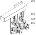
FIG. 8 is an elevational view of a large page suction cup assembly in an embodiment of the present invention;
FIG. 9 is a front view of a large leaf suction cup assembly with the large face suction cup arm mechanism removed in an embodiment of the present invention;
FIG. 10 is a rear view of FIG. 9;
FIG. 11 is an elevational view of a box blank-forming part in an embodiment of the invention;
FIG. 12 is an elevational view of a folding mechanism in an embodiment of the invention;
FIG. 13 is an elevational view of a box pushing member in an embodiment of the invention;
FIG. 14 is an elevational view of the bottom rub cover component in an embodiment of the present invention;
in the figure, 101-box blank warehouse component, 102-box separation component, 103-box opening component, 104-box blank forming component, 105-box pushing component, 106-box rolling bottom sealing component, 107-rack component;
201-box blank conveying assembly, 202-box blank width regulating assembly;
301-lower binning component, 302-upper binning component; 303-box separation air cylinder, 304-top plate, 305-upper box separation lower plate and 306-air cylinder with guide rod;
401-unpacking rack component, 402-small leaf sucker component, 403-large leaf sucker component, 404-box pressing connecting rod component;
4111-a cross beam, 4112-a base linear slide rail, 4113-a blocking component, 4114-a mounting seat, 4115-a clamping block, 4116-a trunnion, 4117-a base translation system, 4118-a servo motor;
4121-upright column, 4122-upright column linear slide rail, 4123-blocking device, 4124-motor reducer base, 4125-motor reducer, 4126-rack, 4127-drag chain system;
4131-base slide, 4132-base, 4133-first connecting pin, 4134-mount, 4135-link, 4136-third connecting pin;
4201-small leaf swing arm base, 4202-small leaf swing arm, 4203-small leaf sucker arm, 4204-small leaf cylinder mounting frame, 4205-sucker connecting plate, 4206-cylinder fixing plate, 4207-cylinder, 4208-sucker;
4301-large-face swing arm, 4302-large-face sucker arm, 4303-sliding block, 4304-bearing, 4305-transition frame, 4306-connecting guide rod, 4307-sliding block locking device, 4308-spring guide rod, 4309-compression spring, 4310-spring partition plate, 4311-large-page cylinder mounting rack, 4312-connecting mounting plate, 4313-screw rod and 4314-pressing handle;
4401-a first connecting rod, 4402-a second connecting rod pin shaft, 4403-a second connecting rod, 4404-a third connecting rod, 4405-a support, 4406-a spindle, 4407-a spindle sleeve, 4408-a spindle locking handle and 4409-a box pressing plate;
501-folding a large page component, 502-folding a small page component, 503-adjusting a large page width and 504-adjusting a small page width;
601-box pushing pipe, 602-box pushing synchronous belt, 603-box pushing motor, 604-box pushing guide rail;
701-box rolling belt component, 702-bottom sealing component and 703-box rolling belt width adjusting component.
Detailed Description
The present invention will be described in detail below with reference to the accompanying drawings and examples.
Referring to fig. 1 to 14, a vertical high-speed case unpacking machine in an embodiment of the present invention includes a frame component, a case blank warehouse component, a case unpacking component, a case blank forming component, a case pushing component, and a case twisting and bottom sealing component, which are disposed on the frame component, wherein an output end of the case blank warehouse component is in butt joint with an input end of the case unpacking component, the case blank forming component is disposed below the case unpacking component, the case pushing component is disposed on one side of the case blank forming component, and an input end of the case twisting and bottom sealing component is in butt joint with an output end of the case blank forming component; the carton opening component is used for pulling up one side of a carton blank to enable the carton to be vertically placed on the carton blank forming component, the upper opening and the bottom of the formed carton face the upper side and the lower side, then the carton blank forming component folds the bottom of the carton into small sheets for forming, the carton pushing component is used for pushing the carton blank from the carton blank forming component to the carton twisting and bottom sealing component, the carton twisting and bottom sealing component folds the bottom of the carton into large sheets for forming, and the bottom of the carton is automatically sealed by an adhesive tape, so that the vertical carton opening of the carton is realized.
Furthermore, the vertical high-speed case unpacking machine also comprises a case separating component, and the case separating component is arranged at the output end of the case blank storage component.
The box opening method of the vertical high-speed box opener comprises the following steps:
1) vertically placing the box blanks in a box blank warehouse part of a box unpacking machine;
2) separating the outermost box blanks of the box blank storage components by a box separating mechanism of the box unpacking machine and jacking the outermost box blanks into box unpacking components of the box unpacking machine;
3) after the opening part absorbs the box surfaces on the two sides of the box blank, one box surface translates and rapidly rotates at the same time, the folded box blank of the carton is pulled open to be in a shape like a Chinese character 'kou', and the opening molding of the carton is completed;
4) the opening part moves the paper box in the shape of the Chinese character kou downwards, a box blank forming part of the box opening machine folds small pages at the bottom of the paper box in the downwards moving process, and folds large pages after downwards moving is completed, so that the bottom of the paper box is formed;
4) the box pushing component pushes the paper box to the box twisting and bottom sealing component;
5) the bottom twisting and sealing part seals the bottom of the carton and outputs the carton to the next link.
The box separation component comprises an upper box separation component 302 and a lower box separation component 301, and the upper box separation component 302 is arranged above the lower box separation component 301;
the lower box separating assembly comprises a box separating cylinder 303, a guide rod and a top plate 304, the box separating cylinder is fixedly arranged on the rack part and is connected with the top plate through the guide rod, and the box separating cylinder drives the top plate to move up and down through the guide rod to push a single carton blank upwards;
the upper box-separating component comprises a cylinder 306 with a guide rod and an upper box-separating lower plate 305, the cylinder with the guide rod is arranged vertically downwards, and the cylinder with the guide rod is connected with the upper box-separating lower plate to drive the upper box-separating lower plate to move up and down.
The box separating component is used for separating the box blanks on the outermost side of the box blanks stacked together on the box blank storage component, and the specific process is as follows: the upper box-separating component is provided with a cylinder with a guide rod, the cylinder with the guide rod drives the upper box-separating lower plate to push out the outermost box blank downwards, the cylinder with the guide rod drives the upper box-separating lower plate to move upwards, the upper end of the outermost box blank is separated from other box blanks in the box blank warehouse component, the lower end of the outermost box blank is still supported by the top plate of the lower box-separating component, the cylinder with the guide rod drives the upper box-separating lower plate to move downwards, the upper ends of other subsequent box blanks in the box blank warehouse component are supported, the box-separating cylinder of the lower box-separating component drives the top plate to push out the outermost box blank upwards, the outermost box blank is separated from other subsequent box blanks in the box blank warehouse component, and the box-separating cylinder drives the top plate to move downwards and supports the lower ends of other subsequent box blanks in the box blank warehouse component.
Furthermore, the upper box-separating assembly further comprises a lifting screw rod and a hand wheel, the hand wheel is connected with the cylinder with the guide rod through the lifting screw rod, the hand wheel drives the lifting screw rod to rotate, and the reference position of the upper box-separating lower plate is adjusted up and down to adapt to carton blanks of different specifications.
The top plate and the lower plate of the upper branch box are both L-shaped.
Further, the unpacking part comprises an unpacking rack part 401, a base translation system, a small-page sucker component 402 and a large-page sucker component 403, a beam is arranged on the unpacking rack part, a base linear slide rail is arranged on the beam along the length direction of the beam, a base is arranged on the base linear slide rail through a base slider, the base translation system is arranged on the unpacking rack part and connected with the base, and the base translation system drives the base to move back and forth along the base linear slide rail through the base slider; the small-page sucker component is fixedly arranged on the base, the large-page sucker component is hinged with the base through a mounting seat, the large-page sucker component is fixedly connected with the mounting seat, the mounting seat is hinged with the base through a first connecting pin shaft, a connecting rod is connected between the mounting seat and the cross beam, and two ends of the connecting rod are respectively hinged with the mounting seat and the cross beam;
when the base slide block is at an initial position, the small-page sucker component and the large-page sucker component are oppositely arranged at two sides of a box blank reserved gap, the box splitting component separates and jacks the box blank at the outermost layer of the box blank warehouse into the box blank reserved gap between the small-page sucker component and the large-page sucker component, the box blank reserved gap is respectively used for sucking the small-page box surface and the large-page box surface of the box blank of the carton, after the base translation system drives the base slide block to move forwards along a base linear slide rail, the small-page sucker translates along with the base, and after the large-page sucker component translates along with the base for a certain distance, the translation is simultaneously rotated for 90 degrees; the small-page sucker component and the large-page sucker component pull the box blank from the small pages and the large pages on two sides of the box blank, and the flat box blank is pulled to be in a shape like a Chinese character 'kou'.
Further, a vertical moving device is arranged between the unpacking rack component 401 and the cross beam; the vertical moving device drives the cross beam to move up and down;
the vertical moving device comprises an upright column, an upright column linear slide rail 4122 fixed on the upright column 4121, a motor reducer base, a motor reducer and a rack 4126 fixed on the upright column 4121, wherein the motor reducer is fixedly arranged on the unpacking rack part through the motor reducer base, the rack is arranged along the length direction of the upright column linear slide rail, the upright column linear slide rail 4122 is in sliding connection with the motor reducer base 4124, the output end of the motor reducer is connected with a gear, the gear is meshed with the rack, and the beam is fixedly connected with the lower end of the upright column; the motor reducer drives the upright post and the cross beam to vertically move up and down through the gear and the rack.
Further, the small-page sucker assembly comprises a small-page swing arm base 4201, a small-page swing arm 4202, a small-page sucker arm 4203, a small-page cylinder mounting rack 4204, a cylinder 4207, a sucker connecting plate 4205 and a sucker 4208, the small-page swing arm is fixedly connected with the base through the small-page swing arm base, the upper end of the small-page sucker arm is connected with the small-page swing arm, the cylinder is fixedly arranged on the small-page sucker arm through the small-page cylinder mounting rack, the sucker connecting plate is connected with a piston rod of the cylinder, and the sucker is arranged on the sucker connecting plate;
further, the cylinder sets firmly on little page or leaf cylinder mounting bracket through the cylinder fixed plate.
Big page of sucking disc subassembly 403 includes big face swing arm 4301, big face sucking disc arm 4302, big page or leaf cylinder mounting bracket 4311, cylinder 4207, sucking disc connecting plate 4205 and sucking disc 4208, and big face swing arm with be connected mount pad fixed connection, the upper end and the big face swing arm of big face sucking disc arm are connected, the cylinder passes through big page or leaf cylinder mounting bracket and sets up on big face sucking disc arm, sucking disc connecting plate 4205 is connected with the piston rod of cylinder, the sucking disc arranges on the sucking disc connecting plate.
Further, the large-page sucker assembly 403 comprises a plurality of large-face sucker arms 4302, the large-face sucker arms 4302 are sequentially arranged along the length direction of the large-face swing arm 4301, and each large-face sucker arm 4302 is internally provided with a large-page cylinder mounting rack 4311, a cylinder 4207, a sucker connecting plate 4205 and a sucker 4208 correspondingly.
Furthermore, the number of the large-area sucker arms 4302 is 2-3.
Further, the cylinder sets firmly on big page or leaf cylinder mounting bracket through the cylinder fixed plate.
Furthermore, a movement adjusting and locking device is connected between the large-area sucker arm and the large-area swing arm, and the large-area sucker arm moves back and forth along the length of the large-area swing arm through the movement adjusting and locking device to adjust the position;
the mobile adjustment locking device comprises a sliding block, a bearing 4304 arranged on the sliding block 4303, a connecting guide rod 4306, a sliding block locking device 4307 and a transition frame 4305, wherein the sliding block 4303 provided with the bearing 4304 is arranged on the large-area swing arm 4301 and can slide along the length direction of the large-area swing arm, one end of the connecting guide rod is connected with the sliding block, the other end of the connecting guide rod penetrates through the large-area swing arm and the large-area sucker arm and is fixedly connected with the transition frame through a nut, and the sliding block locking device is connected between the transition frame and the large-area sucker arm;
the slide block locking device comprises a connecting mounting plate, a screw rod and a pressing handle, the connecting mounting plate is fixedly arranged on the large-area sucker arm, the pressing handle is hinged with the connecting mounting plate, one end of the screw rod is connected with the pressing handle, the other end of the screw rod is fixedly connected with the transition frame through a nut, and a return spring is connected between the screw rod and the pressing handle; when the pressing handle is pulled up, the return spring drives the screw rod and the transition frame to integrally return and move upwards, so that the slide block and the large swing arm are separated from the tightly-pushed state.
Furthermore, the large-page cylinder mounting rack is arranged in the frame of the large-face sucker arm, the spring guide rod transversely penetrates through the large-page cylinder mounting rack, two ends of the spring guide rod are respectively connected with two sides of the large-face sucker arm, and the large-page cylinder mounting rack is hung on the spring guide rod;
furthermore, the middle part of the spring guide rod is connected with a spring partition plate, compression springs are uniformly arranged on two sides of the spring partition plate, the compression springs are sleeved on the spring guide rod, one end of each compression spring is connected with the spring partition plate, and the other end of each compression spring is connected with the large-leaf cylinder mounting frame on the corresponding side;
the number of spring guide bars is two, and two spring guide bars are parallel arrangement respectively in the upper and lower both ends of big page or leaf cylinder mounting bracket.
Further, the number of spring guide rods is two, and two spring guide rods are arranged at the upper end and the lower end of the large-page cylinder mounting frame respectively.
Further, a box pressing connecting rod component 4 is arranged above a box blank reserved gap between the small-page sucker component 402 and the large-page sucker component 403;
the box pressing connecting rod assembly 4 comprises a first connecting rod 4401, a second connecting rod 4403, a third connecting rod 4404, a connecting rod pin roll 4402, a support 4405, a main shaft 4406, a main shaft sleeve 4407, a main shaft locking handle 4408 and a box pressing plate 4409, wherein the first connecting rod is fixedly arranged on the base through a small-page swing arm, the first connecting rod 4401, the second connecting rod 4403 and the third connecting rod 4404 are hinged through the connecting rod pin roll 4402 in sequence and can rotate around the corresponding connecting rod pin roll 4402, and the third connecting rod 4404 and the support 4405 are connected through the main shaft 4406 and can rotate around the main shaft 4406; the spindle sleeve 4407 is sleeved on the spindle 4406 and can slide along the spindle 4406, and the position of the spindle sleeve 4407 on the spindle 4406 is fixed through a spindle locking handle 4408 so as to meet the requirements of different carton blanks in height; the box pressing plate 4409 is fixed on the spindle sleeve 4407, and the lower end of the box pressing plate 4409 is used for pressing the carton blanks.
Further, the base translation system is an electric cylinder or a hydraulic cylinder.
Further, in step 3), the folded carton blank is pulled open into a shape like a Chinese character 'kou', and the specific process of completing the carton opening forming of the carton is as follows: before unpacking, a piston rod of a base translation system 4117 is in an extending state, a small-page sucker component 402 and a large-page sucker component 403 are in a parallel state, piston rods of 3 cylinders 4207 on the two sucker components are in a retracting state, a slit is formed in the process, a carton blank is pushed into the slit by a lower box splitting component of the unpacking machine, and the upper part of the carton blank is limited by a box pressing plate 409; at the moment, the suction cup cylinder begins to extend out, the suction cup respectively sucks the small page box surface and the large page box surface, then the electric cylinder piston rod retracts to drive the small page suction cup component to translate, the large page suction cup component translates and rotates, the folded carton blank is pulled open to be in a shape like a Chinese character 'kou', and carton opening is completed.
Furthermore, the box blank forming part comprises a small folding page assembly, a large page width adjusting assembly and a small page width adjusting assembly, the small folding page assembly comprises two small folding page mechanisms, the two small folding page mechanisms are transversely and oppositely arranged and are connected with the small page width adjusting assembly, and the small page width adjusting assembly is used for adjusting the distance between the two small folding page mechanisms; the big page or leaf subassembly of book includes two big page or leaf mechanisms of book, and two big page or leaf mechanisms of book are along vertical relative arrangement in the both sides of folding little page or leaf subassembly, and two big page or leaf mechanisms of book are connected with big page or leaf width adjustment subassembly respectively, and big page or leaf width adjustment subassembly is used for adjusting two distances of folding between the big page or leaf mechanism.
Furthermore, the small page folding mechanism comprises a page folding base 8-1, a first rocker 8-2, a second rocker 8-4, a page folding plate 8-10 and a page folding cylinder 8-9, wherein the page folding cylinder 8-9 is arranged on the page folding base 8-1, the page folding plate 8-10 is respectively hinged with one end of the first rocker 8-2 and one end of the second rocker 8-4, the other end of the first rocker 8-2 and the other end of the second rocker 8-4 are respectively hinged with the page folding base 8-1, and a piston rod of the page folding cylinder 8-9 is hinged with the first rocker 8-2; the folding cylinder drives the folding plate to turn over through a rocker, and small pages of the carton are folded and formed;
furthermore, a folding connecting rod 8-3 is fixedly arranged on the inner side surface of the folding plate 8-10, and the folding plate 8-10 is hinged with the first rocker 8-2 and the second rocker 8-4 through the folding connecting rod 8-3;
the folding base 8-1, the first rocker 8-2, the folding connecting rod 8-3 and the second rocker 8-4 are connected end to end, and are connected with each other through 4 pin shafts 8-5 to form a plane four-bar mechanism; a piston rod of the folding cylinder 8-9 is hinged with the first rocker 8-2 through a fisheye joint 8-6; the folding cylinder 8-9 is hinged with the folding base 8-1 through a cylinder trunnion support 8-8; when the piston rod of the folding cylinder 8-9 extends out, the folding plates 8-10 are obliquely arranged, and when the piston rod of the folding cylinder 8-9 retracts, the folding plates 8-10 rotate to be horizontal; the lower ends of the folding plates 8-10 are connected with a folding plate;
furthermore, the number of the small folding mechanisms is two, and the two small opening and folding mechanisms are oppositely arranged on two sides of the carton opening forming position; when piston rods of folding cylinders 8-9 of the small folding mechanisms of the two box unpacking machines are extended, two folding plates 8-10 are oppositely arranged in a V shape.
Further, in steps 3) and 4), the carton opening and bottom folding process comprises the following steps: after the base translation system drives the base sliding block to move forwards along the base linear sliding rail, the small-page sucker translates along with the base to drive the small-page box surface to translate, after the large-page sucker assembly translates along with the base for a certain distance, the large-page sucker assembly rotates around a hinged point along with the mounting seat through the connecting rod, and the large-page sucker assembly drives the large-page box surface to translate and rotate for 90 degrees simultaneously; the small-page sucker component and the large-page sucker component pull the box blank from the small-page box surface and the large-page box surface on two sides of the box blank, and the flat box blank is pulled to be in a shape like a Chinese character 'kou'; the folding plates 8-10 are obliquely arranged, the vertical moving device drives the pulled box blank to move downwards, and when a small page at the bottom of the box blank is contacted with the folding plates 8-10, a piston rod of the folding cylinder 8-9 begins to retract; the folding plates 8-10 rotate, and simultaneously, the box blank contacts with the folding plates 8-10 to move downwards; the folding plates 8-10 are turned to be horizontal from the inclination, so as to drive the small pages at the bottom of the box blank to be folded to be horizontal, and the folding of the small pages of the box blank is completed.
The big page or leaf mechanism of book includes two big page or leaf boards of book, two big page or leaf seats of book and two big page or leaf cylinders of book, two big page or leaf seats of book are along longitudinal arrangement, and be connected with big page or leaf width adjusting part, big page or leaf width adjusting part is used for adjusting two distances of folding between the big page or leaf seat, two big page or leaf boards of book arrange relatively in two big page or leaf seats of book through the pivot, two big page or leaf cylinders of book set up respectively on two big page or leaf seats of book, it is connected with big page or leaf board of book to roll over big page or leaf cylinder of book, it revolutes the axle upset to drive big page or leaf board of book, convert into a certain angle with the carton big page or leaf.
Further, push away the case part including pushing away the case pipe, push away the case motor, push away the case guide rail and push away the case hold-in range, push away the case guide rail along longitudinal arrangement, it all is equipped with the band pulley to push away case guide rail both ends, it is connected with one of them band pulley to push away the case motor, connect through pushing away the case hold-in range between two band pulleys, it is equipped with the slider on the case guide rail to push away, it transversely sets up on the slider to push away the case pipe, and be connected with pushing away the case hold-in range, it pushes away the operation of case hold-in range through the drive to push away the case motor, and through pushing away the case hold-in range drive and push away the case pipe along pushing away case guide rail round trip movement, the carton propelling movement on the case base shaping part is to rubbing case back cover part with the hands.
Furthermore, the box rubbing and bottom sealing component comprises two box rubbing and conveying belts and a glue sealing device which are arranged side by side, a box conveying channel is formed between the two box rubbing and conveying belts, and the box sealing device is arranged between the two box rubbing and conveying belts and arranged at the bottom of the box conveying channel; the two box twisting conveying belts clamp the carton from two sides and drive the carton to move forward, and the carton sealer automatically seals the bottom of the carton in the conveying process of the carton.
Furthermore, the box rubbing conveyor belt comprises two belt wheels, a box rubbing belt and a box rubbing motor, the two belt wheels are sequentially arranged along the box conveying direction, the two belt wheels are connected through the box rubbing belt, and the box rubbing motor is connected with one of the belt wheels.
Furthermore, the bottom sealing component of the box twisting machine further comprises a width adjusting component, and the width adjusting component is respectively connected with the two conveying belts to adjust the distance between the two conveying belts.
Furthermore, box blank forming part includes width adjustment subassembly and two box blank conveying assembly that arrange side by side, and box blank width adjustment subassembly is connected with two box blank conveying assembly respectively, and box blank width adjustment subassembly is used for adjusting the distance between two box blank conveying assembly, adapts to the box blank of different sizes.
The structure of the width adjusting assembly in the big page width adjusting assembly and the little page width adjusting assembly and the box blank forming part and the width adjusting assembly in the box bottom sealing part is basically the same, the width adjusting assembly comprises a sliding block seat, an adjusting screw rod, a hand wheel and an adjusting guide rod, two sliding block seats are arranged on the adjusting guide rod, the adjusting screw rod is connected with the sliding block seat through threads, a conveying belt or a synchronous belt is installed on the sliding block seat, the screw rod is rotated through the hand wheel, the left and right movement of the sliding block seat is driven, and the distance between the conveying belts can be adjusted.
In the large page width adjusting assembly and the small page width adjusting assembly, a large page folding seat or a folding base is connected with a sliding block seat; the adjustment guide rod and the gear spline shaft are installed through the helical gear, and the width adjusting assembly can adjust the distance between the folded large leaf or the folded small leaf and is suitable for cartons with more specifications.
In summary, the invention discloses a vertical high-speed case unpacking machine and a case unpacking method, which comprise a rack protection component, and a case blank storage component, a case separating component, a case unpacking component, a case blank forming component, a case pushing component and a case rubbing bottom sealing component which are arranged on the rack component. The input grabbing position of the box separating component is in butt joint with the output end of the box blank storage component, the output stacking position of the box separating component is in butt joint with the box opening component, the box blank forming component is arranged below the box opening component, and the box pushing component is used for pushing the box blanks from the box blank forming component to the box rubbing bottom sealing component; the box separating component separates box blanks stacked together, the box opening component is used for pulling up one side of a box surface of the box blanks to enable the paper boxes to be vertically placed on the box blank forming component, the opening and the bottom of the formed paper boxes face the upper side and the lower side, the box blank forming component is used for folding the bottom of the paper boxes into small pages for forming, the box rolling and bottom sealing component is used for folding the bottom of the paper boxes into large pages for forming, and automatic adhesive tape bottom sealing is carried out on the bottom of the paper boxes, so that vertical box opening of the paper boxes is realized. The whole process is high-speed and automatic, and is particularly suitable for opening the bagged beverage cartons.
The above is only a preferred embodiment of the present invention, and certainly, the scope of the present invention should not be limited thereby, and therefore, the present invention is not limited by the scope of the claims.
Claims (10)
1. The utility model provides a vertical high-speed case unpacking machine, its characterized in that includes the frame part and sets up case blank storehouse part, unpacking part, case blank shaping part, pushes away case part and rub case back cover part on the frame part, and the output of case blank storehouse part docks with the input of unpacking part, and case blank shaping part sets up in unpacking part below, pushes away the case part and sets up in case blank shaping part one side, rubs the case back cover part's input and the butt joint of case blank shaping part's output.
2. The vertical high-speed case unpacking machine as recited in claim 1, further comprising a case separating component disposed at an output end of the case blank warehouse component, the case separating component comprising an upper case separating component and a lower case separating component, the upper case separating component being disposed above the lower case separating component;
the lower box separation assembly comprises a box separation cylinder, a guide rod and a top plate, the box separation cylinder is fixedly arranged on the rack part and is connected with the top plate through the guide rod, and the box separation cylinder drives the top plate to move up and down through the guide rod;
go up the box-separating subassembly and include area guide rod cylinder and last box-separating hypoplastron, take the guide rod cylinder vertical arranging down, take the guide rod cylinder and go up the box-separating hypoplastron and be connected, drive and go up the box-separating hypoplastron and reciprocate.
3. The vertical high-speed case unpacking machine as claimed in claim 1, wherein the case unpacking component comprises a case unpacking rack component, a base translation system, a base, a small-page sucker component and a large-page sucker component, a beam is arranged on the case unpacking rack component, a base linear slide rail is arranged on the beam along the length direction of the beam, the base is arranged on the base linear slide rail through a base slider, the base translation system is arranged on the case unpacking rack component and connected with the base, and the base translation system drives the base to move back and forth along the base linear slide rail through the base slider; the small-page sucker component is fixedly arranged on the base, the large-page sucker component is hinged with the base through a mounting seat, the large-page sucker component is fixedly connected with the mounting seat, the mounting seat is hinged with the base through a first connecting pin shaft, a connecting rod is connected between the mounting seat and the cross beam, and two ends of the connecting rod are respectively hinged with the mounting seat and the cross beam;
when the base sliding block is at the initial position, the small-page sucker component and the large-page sucker component are oppositely arranged at two sides of a box blank reserved gap and are respectively used for sucking small pages and large pages of a carton blank, the base translation system drives the base sliding block to move forwards along the base linear sliding rail, the small-page sucker translates along with the base, and the large-page sucker component translates along with the base for a distance and rotates for 90 degrees at the same time; the small-page sucker component and the large-page sucker component pull the box blank from the small pages and the large pages on two sides of the box blank, and the flat box blank is pulled to be in a shape like a Chinese character 'kou'.
4. A vertical high speed case unpacking machine as claimed in claim 3 wherein vertical movement means are provided between the case unpacking frame members and the cross beams; the vertical moving device drives the cross beam to move up and down.
5. The vertical high-speed case unpacking machine according to claim 3, characterized in that the small-leaf sucker assembly comprises a small-leaf swing arm base, a small-leaf swing arm, a small-leaf sucker arm, a small-leaf cylinder mounting frame, a cylinder, a sucker connecting plate and a sucker, wherein the small-leaf swing arm is fixedly connected with the base through the small-leaf swing arm base, the upper end of the small-leaf sucker arm is connected with the small-leaf swing arm, the cylinder is fixedly arranged on the small-leaf sucker arm through the small-leaf cylinder mounting frame, the sucker connecting plate is connected with a piston rod of the cylinder, and the sucker is arranged on the sucker connecting plate;
big page or leaf sucking disc subassembly includes big face swing arm, big face sucking disc arm, big page or leaf cylinder mounting bracket, cylinder, sucking disc connecting plate and sucking disc, big face swing arm with be connected mount pad fixed connection, the upper end and the big face swing arm of big face sucking disc arm are connected, the cylinder sets up on big face sucking disc arm through big page or leaf cylinder mounting bracket, the sucking disc connecting plate is connected with the piston rod of cylinder, the sucking disc arranges on the sucking disc connecting plate.
6. The vertical high-speed case unpacking machine as recited in claim 5, wherein a movement adjusting and locking device is connected between the large surface suction disc arm and the large surface swing arm, and the large surface suction disc arm moves back and forth along the length of the large surface swing arm through the movement adjusting and locking device to adjust the position.
7. The vertical high-speed case unpacking machine as claimed in claim 6, wherein the movement adjusting and locking device comprises a slider, a bearing arranged on the slider, a connecting guide rod, a slider locking device and a transition frame, the slider provided with the bearing is arranged on the large swing arm and can slide along the length direction of the large swing arm, one end of the connecting guide rod is connected with the slider, the other end of the connecting guide rod penetrates through the large swing arm and the large suction disc arm and is fixedly connected with the transition frame through a nut, the slider locking device is connected between the transition frame and the large suction disc arm, when the slider locking device is pressed down, the slider and the large swing arm are tightly propped, and the slider and the large swing arm are relatively fixed in position to form locking fixation;
the slide block locking device comprises a connecting mounting plate, a screw rod and a pressing handle, the connecting mounting plate is fixedly arranged on the large-area sucker arm, the pressing handle is hinged with the connecting mounting plate, one end of the screw rod is connected with the pressing handle, the other end of the screw rod is fixedly connected with the transition frame through a nut, and a return spring is connected between the screw rod and the pressing handle; when the pressing handle is pulled up, the return spring drives the screw rod and the transition frame to integrally return and move upwards, so that the slide block and the large swing arm are separated from the tightly-pushed state.
8. The vertical high-speed case unpacking machine of claim 1, wherein the case blank forming part comprises a small folding page assembly, a large page width adjusting assembly and a small page width adjusting assembly, the small folding page assembly comprises two small folding page mechanisms, the two small folding page mechanisms are transversely arranged oppositely and are connected with the small page width adjusting assembly, and the small page width adjusting assembly is used for adjusting the distance between the two small folding page mechanisms; the big page or leaf subassembly of book includes two big page or leaf mechanisms of book, and two big page or leaf mechanisms of book are along vertical relative arrangement in the both sides of folding little page or leaf subassembly, and two big page or leaf mechanisms of book are connected with big page or leaf width adjustment subassembly respectively, and big page or leaf width adjustment subassembly is used for adjusting two distances of folding between the big page or leaf mechanism.
9. The vertical high-speed case unpacking machine of claim 8, wherein the small folding mechanism comprises a folding base, a first rocker, a second rocker, a folding plate and a folding cylinder, the folding cylinder is arranged on the folding base, the folding plate is respectively hinged with one end of the first rocker and one end of the second rocker, the other end of the first rocker and the other end of the second rocker are respectively hinged with the folding base, and a piston rod of the folding cylinder is hinged with the first rocker; the folding cylinder drives the folding plate to turn over through a rocker, and small pages of the carton are folded and formed;
the big page or leaf mechanism of book includes two big page or leaf boards of book, two big page or leaf seats of book and two big page or leaf cylinders of book, two big page or leaf seats of book are along longitudinal arrangement, and be connected with big page or leaf width adjusting part, big page or leaf width adjusting part is used for adjusting two distances of folding between the big page or leaf seat, two big page or leaf boards of book arrange relatively in two big page or leaf seats of book through the pivot, two big page or leaf cylinders of book set up respectively on two big page or leaf seats of book, it is connected with big page or leaf board of book to roll over big page or leaf cylinder of book, it revolutes the axle upset to drive big page or leaf board of book, convert into a certain angle with the carton big page or leaf.
10. The vertical high-speed case unpacking machine according to claim 1, wherein the case pushing component comprises a case pushing pipe, a case pushing motor, a case pushing guide rail and a case pushing synchronous belt, the case pushing guide rail is arranged along the longitudinal direction, both ends of the case pushing guide rail are provided with belt wheels, the case pushing motor is connected with one of the belt wheels, the two belt wheels are connected through the case pushing synchronous belt, the case pushing guide rail is provided with a slide block, the case pushing pipe is transversely arranged on the slide block and connected with the case pushing synchronous belt, the case pushing motor drives the case pushing synchronous belt to run through driving, and drives the case pushing pipe to move back and forth along the case pushing guide rail through the case pushing synchronous belt, so that the carton on the case blank forming component is pushed to the case rubbing bottom sealing component.
Priority Applications (1)
| Application Number | Priority Date | Filing Date | Title |
|---|---|---|---|
| CN202110680417.7A CN113479402B (en) | 2021-06-18 | 2021-06-18 | Vertical high-speed case unpacking machine |
Applications Claiming Priority (1)
| Application Number | Priority Date | Filing Date | Title |
|---|---|---|---|
| CN202110680417.7A CN113479402B (en) | 2021-06-18 | 2021-06-18 | Vertical high-speed case unpacking machine |
Publications (2)
| Publication Number | Publication Date |
|---|---|
| CN113479402A true CN113479402A (en) | 2021-10-08 |
| CN113479402B CN113479402B (en) | 2023-02-14 |
Family
ID=77935519
Family Applications (1)
| Application Number | Title | Priority Date | Filing Date |
|---|---|---|---|
| CN202110680417.7A Active CN113479402B (en) | 2021-06-18 | 2021-06-18 | Vertical high-speed case unpacking machine |
Country Status (1)
| Country | Link |
|---|---|
| CN (1) | CN113479402B (en) |
Cited By (2)
| Publication number | Priority date | Publication date | Assignee | Title |
|---|---|---|---|---|
| CN114671084A (en) * | 2020-12-24 | 2022-06-28 | 武汉人天包装自动化技术股份有限公司 | an unpacking mechanism |
| CN116923798A (en) * | 2022-04-08 | 2023-10-24 | 深圳拓新包装机械有限公司 | Vertical linear automatic box opening equipment |
Citations (8)
| Publication number | Priority date | Publication date | Assignee | Title |
|---|---|---|---|---|
| EP0063484A2 (en) * | 1981-04-17 | 1982-10-27 | Western Packaging Systems Limited | Case erector and sealer using high speed cold-cure adhesive |
| CN105026270A (en) * | 2013-02-28 | 2015-11-04 | 韩国杰派有限公司 | Box opening apparatus integrated with stand in box forming apparatus |
| CN106672327A (en) * | 2017-03-03 | 2017-05-17 | 瑞安市春余机械有限公司 | Full-automatic case packing machine |
| CN108394586A (en) * | 2018-05-02 | 2018-08-14 | 温州庄机械科技有限公司 | Automatic boxing machine |
| CN109018530A (en) * | 2018-09-13 | 2018-12-18 | 南通通机股份有限公司 | A kind of novel high speed takes case and unpacking mechanism |
| CN109250208A (en) * | 2018-10-19 | 2019-01-22 | 厦门佳创科技股份有限公司 | Box blank lifting mechanism and box opening device |
| CN211033209U (en) * | 2019-07-23 | 2020-07-17 | 上海普莱克斯自动设备制造有限公司 | Unpacking and sealing device |
| CN111824511A (en) * | 2019-04-17 | 2020-10-27 | 广州市鑫达机械制造有限公司 | Vertical product packaging equipment and packaging method |
-
2021
- 2021-06-18 CN CN202110680417.7A patent/CN113479402B/en active Active
Patent Citations (8)
| Publication number | Priority date | Publication date | Assignee | Title |
|---|---|---|---|---|
| EP0063484A2 (en) * | 1981-04-17 | 1982-10-27 | Western Packaging Systems Limited | Case erector and sealer using high speed cold-cure adhesive |
| CN105026270A (en) * | 2013-02-28 | 2015-11-04 | 韩国杰派有限公司 | Box opening apparatus integrated with stand in box forming apparatus |
| CN106672327A (en) * | 2017-03-03 | 2017-05-17 | 瑞安市春余机械有限公司 | Full-automatic case packing machine |
| CN108394586A (en) * | 2018-05-02 | 2018-08-14 | 温州庄机械科技有限公司 | Automatic boxing machine |
| CN109018530A (en) * | 2018-09-13 | 2018-12-18 | 南通通机股份有限公司 | A kind of novel high speed takes case and unpacking mechanism |
| CN109250208A (en) * | 2018-10-19 | 2019-01-22 | 厦门佳创科技股份有限公司 | Box blank lifting mechanism and box opening device |
| CN111824511A (en) * | 2019-04-17 | 2020-10-27 | 广州市鑫达机械制造有限公司 | Vertical product packaging equipment and packaging method |
| CN211033209U (en) * | 2019-07-23 | 2020-07-17 | 上海普莱克斯自动设备制造有限公司 | Unpacking and sealing device |
Cited By (2)
| Publication number | Priority date | Publication date | Assignee | Title |
|---|---|---|---|---|
| CN114671084A (en) * | 2020-12-24 | 2022-06-28 | 武汉人天包装自动化技术股份有限公司 | an unpacking mechanism |
| CN116923798A (en) * | 2022-04-08 | 2023-10-24 | 深圳拓新包装机械有限公司 | Vertical linear automatic box opening equipment |
Also Published As
| Publication number | Publication date |
|---|---|
| CN113479402B (en) | 2023-02-14 |
Similar Documents
| Publication | Publication Date | Title |
|---|---|---|
| CN113479401B (en) | Unpacking method of vertical high-speed unpacking machine | |
| CN106586090B (en) | Multifunctional high-speed packaging machine | |
| US20130090222A1 (en) | Apparatus and methods for folding paper boxes | |
| CN210338481U (en) | Automatic box filling machine | |
| CN113479402B (en) | Vertical high-speed case unpacking machine | |
| CN113291538B (en) | Intelligent vertical automatic boxing and case sealing machine | |
| CN115071207A (en) | Box folding method, automatic box folding machine and working method thereof | |
| CN115959353A (en) | Whole-product standard cigarette unpacking system and unpacking method thereof | |
| CN114789822A (en) | Carton automatic molding joint sealing equipment | |
| CN112441284A (en) | High-speed unpacking and paper folding device | |
| CN212314039U (en) | Three-dimensional wrapping machine | |
| CN214140936U (en) | an origami machine | |
| CN112224496B (en) | Welding rod boxing equipment | |
| CN210338472U (en) | Carton unpacking machine | |
| CN116176946B (en) | Vertical box unpacking machine and use method thereof | |
| WO2014066015A1 (en) | Apparatus and methods for folding paper boxes | |
| CN220763680U (en) | Folding box forming machine | |
| CN221114604U (en) | Blood product packaging device | |
| CN218199092U (en) | Carton unpacking and sealing all-in-one machine | |
| CN112299102A (en) | Arrangement and stacking device after paperboard cutting | |
| CN219428431U (en) | Packing device | |
| CN214383429U (en) | Box opening mechanism | |
| CN115231060B (en) | Lifting rotary box scraping mechanism and working method thereof | |
| CN118288613A (en) | Automatic folding device and folding method for paper boxes | |
| CN117799224A (en) | An automatic carton forming device |
Legal Events
| Date | Code | Title | Description |
|---|---|---|---|
| PB01 | Publication | ||
| PB01 | Publication | ||
| SE01 | Entry into force of request for substantive examination | ||
| SE01 | Entry into force of request for substantive examination | ||
| GR01 | Patent grant | ||
| GR01 | Patent grant |