CN113478324A - Grinding device for producing battery steel shell - Google Patents
Grinding device for producing battery steel shell Download PDFInfo
- Publication number
- CN113478324A CN113478324A CN202110621270.4A CN202110621270A CN113478324A CN 113478324 A CN113478324 A CN 113478324A CN 202110621270 A CN202110621270 A CN 202110621270A CN 113478324 A CN113478324 A CN 113478324A
- Authority
- CN
- China
- Prior art keywords
- block
- steel shell
- battery steel
- driving motor
- producing
- Prior art date
- Legal status (The legal status is an assumption and is not a legal conclusion. Google has not performed a legal analysis and makes no representation as to the accuracy of the status listed.)
- Pending
Links
- 229910000831 Steel Inorganic materials 0.000 title claims abstract description 70
- 239000010959 steel Substances 0.000 title claims abstract description 70
- 238000005498 polishing Methods 0.000 claims abstract description 35
- 238000009434 installation Methods 0.000 claims description 15
- 230000005540 biological transmission Effects 0.000 claims description 10
- 230000000149 penetrating effect Effects 0.000 claims description 3
- 238000004519 manufacturing process Methods 0.000 abstract description 7
- 230000033001 locomotion Effects 0.000 description 5
- 238000010586 diagram Methods 0.000 description 3
- 230000000694 effects Effects 0.000 description 3
- 230000003139 buffering effect Effects 0.000 description 2
- 238000000034 method Methods 0.000 description 2
- 230000009286 beneficial effect Effects 0.000 description 1
- 239000000463 material Substances 0.000 description 1
- 239000007769 metal material Substances 0.000 description 1
- 238000007517 polishing process Methods 0.000 description 1
- 238000004080 punching Methods 0.000 description 1
Images


Classifications
-
- B—PERFORMING OPERATIONS; TRANSPORTING
- B24—GRINDING; POLISHING
- B24B—MACHINES, DEVICES, OR PROCESSES FOR GRINDING OR POLISHING; DRESSING OR CONDITIONING OF ABRADING SURFACES; FEEDING OF GRINDING, POLISHING, OR LAPPING AGENTS
- B24B9/00—Machines or devices designed for grinding edges or bevels on work or for removing burrs; Accessories therefor
- B24B9/02—Machines or devices designed for grinding edges or bevels on work or for removing burrs; Accessories therefor characterised by a special design with respect to properties of materials specific to articles to be ground
- B24B9/04—Machines or devices designed for grinding edges or bevels on work or for removing burrs; Accessories therefor characterised by a special design with respect to properties of materials specific to articles to be ground of metal, e.g. skate blades
-
- B—PERFORMING OPERATIONS; TRANSPORTING
- B24—GRINDING; POLISHING
- B24B—MACHINES, DEVICES, OR PROCESSES FOR GRINDING OR POLISHING; DRESSING OR CONDITIONING OF ABRADING SURFACES; FEEDING OF GRINDING, POLISHING, OR LAPPING AGENTS
- B24B27/00—Other grinding machines or devices
- B24B27/0046—Column grinding machines
-
- B—PERFORMING OPERATIONS; TRANSPORTING
- B24—GRINDING; POLISHING
- B24B—MACHINES, DEVICES, OR PROCESSES FOR GRINDING OR POLISHING; DRESSING OR CONDITIONING OF ABRADING SURFACES; FEEDING OF GRINDING, POLISHING, OR LAPPING AGENTS
- B24B41/00—Component parts such as frames, beds, carriages, headstocks
- B24B41/005—Feeding or manipulating devices specially adapted to grinding machines
-
- B—PERFORMING OPERATIONS; TRANSPORTING
- B24—GRINDING; POLISHING
- B24B—MACHINES, DEVICES, OR PROCESSES FOR GRINDING OR POLISHING; DRESSING OR CONDITIONING OF ABRADING SURFACES; FEEDING OF GRINDING, POLISHING, OR LAPPING AGENTS
- B24B41/00—Component parts such as frames, beds, carriages, headstocks
- B24B41/007—Weight compensation; Temperature compensation; Vibration damping
-
- B—PERFORMING OPERATIONS; TRANSPORTING
- B24—GRINDING; POLISHING
- B24B—MACHINES, DEVICES, OR PROCESSES FOR GRINDING OR POLISHING; DRESSING OR CONDITIONING OF ABRADING SURFACES; FEEDING OF GRINDING, POLISHING, OR LAPPING AGENTS
- B24B41/00—Component parts such as frames, beds, carriages, headstocks
- B24B41/02—Frames; Beds; Carriages
-
- B—PERFORMING OPERATIONS; TRANSPORTING
- B24—GRINDING; POLISHING
- B24B—MACHINES, DEVICES, OR PROCESSES FOR GRINDING OR POLISHING; DRESSING OR CONDITIONING OF ABRADING SURFACES; FEEDING OF GRINDING, POLISHING, OR LAPPING AGENTS
- B24B41/00—Component parts such as frames, beds, carriages, headstocks
- B24B41/06—Work supports, e.g. adjustable steadies
-
- B—PERFORMING OPERATIONS; TRANSPORTING
- B24—GRINDING; POLISHING
- B24B—MACHINES, DEVICES, OR PROCESSES FOR GRINDING OR POLISHING; DRESSING OR CONDITIONING OF ABRADING SURFACES; FEEDING OF GRINDING, POLISHING, OR LAPPING AGENTS
- B24B47/00—Drives or gearings; Equipment therefor
- B24B47/10—Drives or gearings; Equipment therefor for rotating or reciprocating working-spindles carrying grinding wheels or workpieces
- B24B47/12—Drives or gearings; Equipment therefor for rotating or reciprocating working-spindles carrying grinding wheels or workpieces by mechanical gearing or electric power
-
- B—PERFORMING OPERATIONS; TRANSPORTING
- B24—GRINDING; POLISHING
- B24B—MACHINES, DEVICES, OR PROCESSES FOR GRINDING OR POLISHING; DRESSING OR CONDITIONING OF ABRADING SURFACES; FEEDING OF GRINDING, POLISHING, OR LAPPING AGENTS
- B24B47/00—Drives or gearings; Equipment therefor
- B24B47/20—Drives or gearings; Equipment therefor relating to feed movement
Abstract
The invention discloses a polishing device for producing a battery steel shell, which comprises a base, wherein a flat plate is fixedly arranged on the base, mounting blocks are fixedly arranged at two ends of the flat plate, a screw rod is rotatably arranged between the two mounting blocks, and a moving block which moves in the horizontal direction is connected to the screw rod in a threaded manner. According to the battery steel shell polishing device, a battery steel shell is placed on a protruding block, a third driving motor is started to rotate forwardly to drive the rotating block to rotate forwardly, two sliding blocks are pulled to move inwards through a connecting rod to drive a clamping block to clamp the battery steel shell, a first spring is compressed under stress to fix the battery steel shell on the protruding block, a cylinder is started to drive a piston rod to move downwards to drive a bottom plate and a polishing machine to move downwards, the polishing machine polishes burrs and rough edges on the outer surface wall of the bottom of the battery steel shell, the device polishes the burrs, manual polishing is not needed, polishing time is short, polishing efficiency is high, and production efficiency is improved.
Description
Technical Field
The invention relates to the technical field of polishing devices, in particular to a polishing device for producing a battery steel shell.
Background
The battery box hat is the important spare part of constituteing the battery, and the box hat appearance of the battery of different classes is different, and its material is made by metal material mostly, through stamping process production, at the in-process of box hat production, because box hat bottom outer table wall and stamping die direct contact, and the bottom of box hat is main stress point during the punching press, can form deckle edge and burr on the outer table wall of box hat bottom, consequently, need polish deckle edge and burr.
Most polishing modes in the prior art are manually polished, the steel shell is placed on a workbench, one hand of a worker presses the steel shell, the other hand holds a polishing machine to polish the outer surface wall of the bottom of the steel shell, however, firstly, the polishing time of the manual polishing mode is long, the polishing efficiency is low, the production efficiency is reduced, secondly, the hand of the worker presses the steel shell to be difficult to fix the steel shell, and in the polishing process, the steel shell can move, so that the polishing of the steel shell is not convenient.
Disclosure of Invention
In order to solve the technical problems mentioned in the background art, the grinding device for producing the battery steel shell is provided.
In order to achieve the purpose, the invention adopts the following technical scheme:
the polishing device for producing the battery steel shell comprises a base, wherein a flat plate is fixedly arranged on the base, mounting blocks are fixedly arranged at two ends of the flat plate, a screw rod is rotatably arranged between the two mounting blocks, a moving block which moves in the horizontal direction is connected to the screw rod in a threaded manner, an air cylinder is fixedly arranged on the moving block, a bottom plate is fixedly arranged on a piston rod of the air cylinder, and a polishing machine is fixedly arranged on the bottom plate;
a convex block is fixedly installed at the center of the flat plate, an installation groove and a sliding groove are formed in the convex block, an ejection rod is connected in the sliding groove in a sliding mode, an elliptical disc is installed in the installation groove in a rotating mode, the bottom of the ejection rod is abutted against the top of the elliptical disc, a limiting block is fixedly installed on the outer side of the ejection rod, and the limiting block is elastically connected with the inner surface wall of the installation groove through a second spring;
the mounting block is provided with a first driving mechanism for driving the screw rod to rotate, a second driving mechanism for driving the elliptical disk to rotate is arranged in the mounting groove, and the flat plate is provided with a clamping mechanism.
As a further description of the above technical solution:
the clamping mechanism comprises a clamping block, two through grooves are formed in the flat plate, the two through grooves are symmetrical with respect to the axis center of the lug, a second guide rod is fixedly mounted in the base, two sliding blocks are connected to the second guide rod in a sliding mode, the tops of the sliding blocks are fixedly connected with connecting blocks moving in the through grooves, a moving block is fixedly mounted at the tops of the connecting blocks, a first spring is connected to the moving block in an elastic mode, the free end of the first spring is connected with the clamping block in an elastic mode, and a third driving mechanism for driving the sliding blocks to move is arranged in the base.
As a further description of the above technical solution:
the third driving mechanism comprises a third driving motor, the third driving motor is fixedly mounted in the base, a rotating block is connected to an output shaft of the third driving motor in a transmission mode, second fixing columns are fixedly connected to two ends of the rotating block, first fixing columns are fixedly connected to the bottoms of the sliding blocks, connecting rods are rotatably mounted on the first fixing columns, and free ends of the connecting rods are rotatably mounted with the second fixing columns.
As a further description of the above technical solution:
the first driving mechanism comprises a first driving motor, the mounting block is fixedly provided with the first driving motor, and an output shaft of the first driving motor is in transmission connection with the screw rod.
As a further description of the above technical solution:
the second driving mechanism comprises a second driving motor, the second driving motor is fixedly mounted in the mounting groove, and an output shaft of the second driving motor is in transmission connection with the elliptical disc.
As a further description of the above technical solution:
the movable block is fixedly provided with a telescopic rod, the free end of the telescopic rod is fixedly installed with the clamping block, and the first spring is sleeved outside the telescopic rod.
As a further description of the above technical solution:
and a first guide rod penetrating through the moving block is fixedly arranged between the two mounting blocks, and the axis direction of the first guide rod is parallel to the axis direction of the screw rod.
As a further description of the above technical solution:
the clamping end of the clamping block is arc-shaped, and a rubber layer is bonded on the inner surface wall of the clamping end of the clamping block.
As a further description of the above technical solution:
and the third driving motor is fixedly arranged in the base through a bolt.
As a further description of the above technical solution:
the connecting block is welded on the sliding block.
In summary, due to the adoption of the technical scheme, the invention has the beneficial effects that:
1. according to the battery steel shell polishing device, a battery steel shell is placed on a protruding block, a third driving motor is started to rotate forwardly to drive the rotating block to rotate forwardly, two sliding blocks are pulled to move inwards through a connecting rod to drive a clamping block to clamp the battery steel shell, a first spring is compressed under stress to fix the battery steel shell on the protruding block, a cylinder is started to drive a piston rod to move downwards to drive a bottom plate and a polishing machine to move downwards, the polishing machine polishes burrs and rough edges on the outer surface wall of the bottom of the battery steel shell, the device polishes the burrs, manual polishing is not needed, polishing time is short, polishing efficiency is high, and production efficiency is improved.
2. According to the battery steel shell fixing device, the battery steel shell is placed on the protruding block, the third driving motor is started to rotate forward to drive the rotating block to rotate forward, the two sliding blocks are pulled to move inwards through the connecting rod to drive the clamping block to clamp the battery steel shell, the first spring is stressed and compressed to fix the battery steel shell on the protruding block, the first spring has a buffering effect, the stability of the device is improved, and the fixing effect of the clamping block on the battery steel shell is enhanced.
3. According to the invention, after polishing is finished, the third driving motor is started to rotate reversely, the clamping block is driven to leave the battery steel shell, the second driving motor is started to rotate, the elliptical disc is driven to rotate, the ejector rod is driven to reciprocate in the vertical direction, the ejector rod moves upwards to eject the battery steel shell, the battery steel shell is prevented from being clamped on the lug and cannot be taken down, and the device is convenient to use.
Drawings
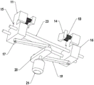
FIG. 1 shows an axial schematic diagram of a grinding device for producing a battery steel shell, provided by the embodiment of the invention;
FIG. 2 is a first angle schematic diagram of a third driving mechanism of the grinding device for producing the battery steel shell, which is provided by the embodiment of the invention;
FIG. 3 is a second angle schematic diagram of a third driving mechanism of the grinding device for producing the steel battery shell, which is provided by the embodiment of the invention;
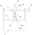
FIG. 4 is a schematic front view illustrating a grinding device for producing a battery steel shell according to an embodiment of the invention;
FIG. 5 is a schematic right-side view illustrating a grinding device for producing a battery steel shell according to an embodiment of the invention;
FIG. 6 is a schematic view of the inside of a bump of a grinding device for producing a steel battery shell, provided by the embodiment of the invention;
fig. 7 shows an enlarged schematic view at a of the grinding device for producing the steel battery case provided by the embodiment of the invention.
Illustration of the drawings:
1. a base; 2. a flat plate; 201. a through groove; 3. mounting blocks; 4. a first guide bar; 5. a screw; 6. a cylinder; 7. a base plate; 8. a sander; 9. a first drive motor; 10. a bump; 1001. mounting grooves; 1002. a sliding groove; 11. a moving block; 12. a telescopic rod; 13. a first spring; 14. a clamping block; 15. connecting blocks; 16. a slider; 17. a first fixed column; 18. a second fixed column; 19. a connecting rod; 20. rotating the block; 21. a third drive motor; 22. a motion block; 23. a second guide bar; 24. ejecting the rod; 25. a limiting block; 26. a second spring; 27. an elliptical disk; 28. a second drive motor.
Detailed Description
The technical solutions in the embodiments of the present invention will be clearly and completely described below with reference to the drawings in the embodiments of the present invention, and it is obvious that the described embodiments are only a part of the embodiments of the present invention, and not all of the embodiments. All other embodiments, which can be derived by a person skilled in the art from the embodiments given herein without making any creative effort, shall fall within the protection scope of the present invention.
Examples
Referring to fig. 1-7, the present invention provides a technical solution: the polishing device for producing the battery steel shell comprises a base 1, wherein a flat plate 2 is fixedly installed on the base 1, installation blocks 3 are fixedly installed at two ends of the flat plate 2, a screw rod 5 is rotatably installed between the two installation blocks 3, a moving block 22 moving in the horizontal direction is connected to the screw rod 5 in a threaded manner, an air cylinder 6 is fixedly installed on the moving block 22, a bottom plate 7 is fixedly installed on a piston rod of the air cylinder 6, and a polishing machine 8 is fixedly installed on the bottom plate 7; a convex block 10 is fixedly installed at the center of the flat plate 2, an installation groove 1001 and a sliding groove 1002 are formed in the convex block 10, an ejection rod 24 is connected in the sliding groove 1002 in a sliding mode, an elliptical disk 27 is installed in the installation groove 1001 in a rotating mode, the bottom of the ejection rod 24 is abutted to the top of the elliptical disk 27, a limiting block 25 is fixedly installed on the outer side of the ejection rod 24, and the limiting block 25 is elastically connected with the inner surface wall of the installation groove 1001 through a second spring 26; be equipped with the first actuating mechanism of drive screw 5 pivoted on the installation piece 3, be equipped with drive elliptical disk 27 pivoted second actuating mechanism in the mounting groove 1001, be equipped with fixture on dull and stereotyped 2, fixture includes clamp splice 14, two logical groove 201 have been seted up on dull and stereotyped 2, two lead to groove 201 about the axis central symmetry of lug 10, fixed mounting has second guide arm 23 in the base 1, sliding connection has two sliding blocks 16 on second guide arm 23, sliding block 16 top fixedly connected with is leading to connecting block 15 of groove 201 internal motion, connecting block 15 top fixed mounting has movable block 11, elastic connection has first spring 13 on the movable block 11, the free end elastic connection of first spring 13 has clamp splice 14, be equipped with the third actuating mechanism of drive sliding block 16 motions in the base 1.
Referring to fig. 1-7, the third driving mechanism includes a third driving motor 21, the base 1 is internally and fixedly provided with the third driving motor 21, an output shaft of the third driving motor 21 is connected with a rotating block 20 in a transmission manner, two ends of the rotating block 20 are fixedly connected with second fixing columns 18, the bottom of the sliding block 16 is fixedly connected with the first fixing columns 17, the first fixing columns 17 are rotatably provided with a connecting rod 19, a free end of the connecting rod 19 is rotatably provided with the second fixing columns 18, the first driving mechanism includes a first driving motor 9, the mounting block 3 is fixedly provided with a first driving motor 9, an output shaft of the first driving motor 9 is in transmission connection with the screw 5, the second driving mechanism includes a second driving motor 28, the mounting groove 1001 is fixedly provided with a second driving motor 28, an output shaft of the second driving motor 28 is in transmission connection with the elliptical disk 27, the moving block 11 is fixedly provided with an expansion link 12, the free end of the telescopic rod 12 is fixedly installed with the clamping block 14, the first spring 13 is sleeved outside the telescopic rod 12, the first guide rod 4 penetrating through the moving block 22 is fixedly installed between the two installation blocks 3, the axis direction of the first guide rod 4 is parallel to the axis direction of the screw 5, the clamping end of the clamping block 14 is arc-shaped, a rubber layer is adhered to the inner surface wall of the clamping end of the clamping block 14, the third driving motor 21 is fixedly installed in the base 1 through bolts, the connecting block 15 is welded on the sliding block 16, the battery steel shell is placed on the lug 10, the third driving motor 21 is started to rotate forwards to drive the rotating block 20 to rotate forwards, the two sliding blocks 16 are pulled to move inwards through the connecting rod 19, the clamping block 14 is further driven to clamp the battery steel shell, the first spring 13 is stressed and compressed to fix the battery steel shell on the lug 10, the first spring 13 has a buffering effect, the stability of the device is improved, and the fixing effect of the clamping block 14 on the battery steel shell is enhanced, start first driving motor 9 and rotate, drive screw rod 5 and rotate, according to the screw thread transmission principle, the direction motion of motion block 22 along first guide arm 4 axis can be adjusted the position of polisher 8 according to actual conditions, conveniently polishes, strengthens the effect of polishing.
The battery steel shell is placed on the lug 10, the third driving motor 21 is started to rotate in the positive direction to drive the rotating block 20 to rotate in the positive direction, the two sliding blocks 16 are pulled to move inwards through the connecting rod 19, the clamping block 14 is further driven to clamp the battery steel shell, the first spring 13 is compressed under stress to fix the battery steel shell on the lug 10, the starting air cylinder 6 drives the piston rod to move downwards, the driving bottom plate 7 and the grinding machine 8 move downwards, when the grinding sheet of the grinding machine 8 is in contact with the outer surface wall of the battery steel shell, the air cylinder 6 is paused, the grinding machine 8 grinds burrs and rough edges on the outer surface wall of the bottom of the battery steel shell, the grinding is carried out through the device, manual grinding is not needed, the grinding time is short, the grinding efficiency is high, the production efficiency is improved, after grinding is finished, the third driving motor 21 is started to rotate in the reverse direction, the driving clamping block 14 is separated from the battery steel shell, the second driving motor 28 is started to rotate, the elliptical disc 27 is driven to rotate, the ejector rod 24 is driven to reciprocate in the vertical direction, the ejector rod 24 moves upwards to eject the battery steel shell, and the battery steel shell is prevented from being clamped on the bump 10 and cannot be taken down, so that the device is convenient to use.
The working principle is as follows: when the battery steel shell polishing device is used, a battery steel shell is placed on a lug 10, a third driving motor 21 is started to rotate in the forward direction to drive a rotating block 20 to rotate in the forward direction, two sliding blocks 16 are pulled to move inwards through a connecting rod 19, a clamping block 14 is further driven to clamp the battery steel shell, a first spring 13 is stressed and compressed to fix the battery steel shell on the lug 10, a cylinder 6 is started to drive a piston rod to move downwards, a bottom plate 7 and a polisher 8 are driven to move downwards, when a polishing sheet of the polisher 8 is in contact with the outer surface wall of the battery steel shell, the cylinder 6 is paused, the polisher 8 polishes burrs and rough edges on the outer surface wall of the bottom of the battery steel shell, manual polishing is not needed, polishing time is short, polishing efficiency is high, production efficiency is improved, after polishing is finished, the third driving motor 21 is started to rotate in the reverse direction, the clamping block 14 is driven to leave the battery steel shell, a second driving motor 28 is started to rotate, and an elliptic disc 27 is driven to rotate, the ejector rod 24 is driven to reciprocate in the vertical direction, the ejector rod 24 moves upwards to eject the battery steel shell, and the battery steel shell is prevented from being clamped on the bump 10 and cannot be taken down, so that the device is convenient to use.
The above description is only for the preferred embodiment of the present invention, but the scope of the present invention is not limited thereto, and any person skilled in the art should be considered to be within the technical scope of the present invention, and the technical solutions and the inventive concepts thereof according to the present invention should be equivalent or changed within the scope of the present invention.
Claims (10)
1. The polishing device for producing the battery steel shell comprises a base (1) and is characterized in that a flat plate (2) is fixedly mounted on the base (1), mounting blocks (3) are fixedly mounted at two ends of the flat plate (2), a screw rod (5) is rotatably mounted between the two mounting blocks (3), a moving block (22) moving in the horizontal direction is connected to the screw rod (5) in a threaded manner, an air cylinder (6) is fixedly mounted on the moving block (22), a bottom plate (7) is fixedly mounted on a piston rod of the air cylinder (6), and a polishing machine (8) is fixedly mounted on the bottom plate (7);
a convex block (10) is fixedly installed at the center of the flat plate (2), an installation groove (1001) and a sliding groove (1002) are formed in the convex block (10), an ejector rod (24) is connected in the sliding groove (1002) in a sliding mode, an elliptical disc (27) is installed in the installation groove (1001) in a rotating mode, the bottom of the ejector rod (24) is abutted to the top of the elliptical disc (27), a limiting block (25) is fixedly installed on the outer side of the ejector rod (24), and the limiting block (25) is elastically connected with the inner surface wall of the installation groove (1001) through a second spring (26);
the mounting block (3) is provided with a first driving mechanism for driving the screw rod (5) to rotate, a second driving mechanism for driving the elliptical disk (27) to rotate is arranged in the mounting groove (1001), and the flat plate (2) is provided with a clamping mechanism.
2. Grinding device for producing battery steel casings according to claim 1, characterized in that the clamping mechanism comprises a clamping block (14), two through grooves (201) are arranged on the flat plate (2), the two through grooves (201) are centrosymmetric about the axis of the bump (10), a second guide rod (23) is fixedly arranged in the base (1), two sliding blocks (16) are connected on the second guide rod (23) in a sliding way, the top of the sliding block (16) is fixedly connected with a connecting block (15) moving in the through groove (201), a moving block (11) is fixedly arranged at the top of the connecting block (15), a first spring (13) is elastically connected to the moving block (11), the free end of the first spring (13) is elastically connected with a clamping block (14), and a third driving mechanism for driving the sliding block (16) to move is arranged in the base (1).
3. The grinding device for producing the battery steel shell as claimed in claim 2, wherein the third driving mechanism comprises a third driving motor (21), the third driving motor (21) is fixedly installed in the base (1), a rotating block (20) is connected to an output shaft of the third driving motor (21) in a transmission manner, second fixing columns (18) are fixedly connected to two ends of the rotating block (20), first fixing columns (17) are fixedly connected to the bottoms of the sliding blocks (16), connecting rods (19) are rotatably installed on the first fixing columns (17), and free ends of the connecting rods (19) are rotatably installed with the second fixing columns (18).
4. The grinding device for producing the battery steel shell as claimed in claim 3, wherein the first driving mechanism comprises a first driving motor (9), the first driving motor (9) is fixedly mounted on the mounting block (3), and an output shaft of the first driving motor (9) is in transmission connection with the screw (5).
5. The grinding device for producing the battery steel shell as claimed in claim 4, wherein the second driving mechanism comprises a second driving motor (28), the second driving motor (28) is fixedly installed in the installation groove (1001), and an output shaft of the second driving motor (28) is in transmission connection with the elliptical disk (27).
6. The grinding device for producing the battery steel shell as claimed in claim 5, wherein a telescopic rod (12) is fixedly mounted on the moving block (11), the free end of the telescopic rod (12) is fixedly mounted with a clamping block (14), and the first spring (13) is sleeved outside the telescopic rod (12).
7. The grinding device for producing the battery steel shell as claimed in claim 6, wherein a first guide rod (4) penetrating through a moving block (22) is fixedly installed between the two installation blocks (3), and the axial direction of the first guide rod (4) is parallel to the axial direction of the screw rod (5).
8. The grinding device for producing the battery steel shell as claimed in claim 7, wherein the clamping end of the clamping block (14) is arc-shaped, and a rubber layer is adhered to the inner surface wall of the clamping end of the clamping block (14).
9. The grinding device for producing the battery steel shell as recited in claim 8, wherein the third driving motor (21) is fixedly installed in the base (1) through bolts.
10. Grinding device for producing battery steel casings according to claim 9, characterized in that the connecting block (15) is welded on the sliding block (16).
Priority Applications (1)
| Application Number | Priority Date | Filing Date | Title |
|---|---|---|---|
| CN202110621270.4A CN113478324A (en) | 2021-06-03 | 2021-06-03 | Grinding device for producing battery steel shell |
Applications Claiming Priority (1)
| Application Number | Priority Date | Filing Date | Title |
|---|---|---|---|
| CN202110621270.4A CN113478324A (en) | 2021-06-03 | 2021-06-03 | Grinding device for producing battery steel shell |
Publications (1)
| Publication Number | Publication Date |
|---|---|
| CN113478324A true CN113478324A (en) | 2021-10-08 |
Family
ID=77934559
Family Applications (1)
| Application Number | Title | Priority Date | Filing Date |
|---|---|---|---|
| CN202110621270.4A Pending CN113478324A (en) | 2021-06-03 | 2021-06-03 | Grinding device for producing battery steel shell |
Country Status (1)
| Country | Link |
|---|---|
| CN (1) | CN113478324A (en) |
Cited By (1)
| Publication number | Priority date | Publication date | Assignee | Title |
|---|---|---|---|---|
| CN114043348A (en) * | 2021-12-07 | 2022-02-15 | 扬州市宝余光电有限公司 | Multi-shape processing device for lens and working method thereof |
Citations (7)
| Publication number | Priority date | Publication date | Assignee | Title |
|---|---|---|---|---|
| CN205630034U (en) * | 2016-05-27 | 2016-10-12 | 盛奇石 | Workpiece clamping device |
| CN207841980U (en) * | 2017-12-25 | 2018-09-11 | 江苏蓝佩得工业科技有限公司 | A kind of secondary ejection device of silica gel mould |
| US20200086449A1 (en) * | 2019-08-01 | 2020-03-19 | Jianhua Yao | A processing apparatus for elliptical annular optical glass |
| CN210255715U (en) * | 2019-06-29 | 2020-04-07 | 河南中磨钻石工具有限公司 | Diamond grinding device |
| CN111730460A (en) * | 2020-07-01 | 2020-10-02 | 马朋飞 | Steel pipe grinding device with remove flavor module |
| CN112720221A (en) * | 2020-12-31 | 2021-04-30 | 朱轶静 | Method for removing and cleaning steel formwork of prefabricated building concrete prefabricated part |
| CN112792207A (en) * | 2020-12-17 | 2021-05-14 | 广州众山精密科技有限公司 | Method for preventing material from being broken and bent |
-
2021
- 2021-06-03 CN CN202110621270.4A patent/CN113478324A/en active Pending
Patent Citations (7)
| Publication number | Priority date | Publication date | Assignee | Title |
|---|---|---|---|---|
| CN205630034U (en) * | 2016-05-27 | 2016-10-12 | 盛奇石 | Workpiece clamping device |
| CN207841980U (en) * | 2017-12-25 | 2018-09-11 | 江苏蓝佩得工业科技有限公司 | A kind of secondary ejection device of silica gel mould |
| CN210255715U (en) * | 2019-06-29 | 2020-04-07 | 河南中磨钻石工具有限公司 | Diamond grinding device |
| US20200086449A1 (en) * | 2019-08-01 | 2020-03-19 | Jianhua Yao | A processing apparatus for elliptical annular optical glass |
| CN111730460A (en) * | 2020-07-01 | 2020-10-02 | 马朋飞 | Steel pipe grinding device with remove flavor module |
| CN112792207A (en) * | 2020-12-17 | 2021-05-14 | 广州众山精密科技有限公司 | Method for preventing material from being broken and bent |
| CN112720221A (en) * | 2020-12-31 | 2021-04-30 | 朱轶静 | Method for removing and cleaning steel formwork of prefabricated building concrete prefabricated part |
Cited By (1)
| Publication number | Priority date | Publication date | Assignee | Title |
|---|---|---|---|---|
| CN114043348A (en) * | 2021-12-07 | 2022-02-15 | 扬州市宝余光电有限公司 | Multi-shape processing device for lens and working method thereof |
Similar Documents
| Publication | Publication Date | Title |
|---|---|---|
| CN210281686U (en) | A terminal surface grinding device for spring processing | |
| CN111299397B (en) | Burr-free stamping die | |
| CN110497299B (en) | Improved motorcycle starting rod machining device and process | |
| CN113478324A (en) | Grinding device for producing battery steel shell | |
| CN210024719U (en) | Rotating shaft polishing device for machining | |
| CN211029341U (en) | Outside grinding device of stainless steel stamping workpiece | |
| CN112388456A (en) | Die end face machining device and machining method thereof | |
| CN212705852U (en) | Burr grinding device is used in production of compressor housing subassembly | |
| CN212653167U (en) | Deburring device for product processing | |
| CN214723186U (en) | Polishing assembly suitable for automobile parts | |
| CN212420681U (en) | Grinding device for steel of adjustable area of polishing | |
| CN213438765U (en) | End face deburring device for gear production | |
| CN212578429U (en) | Positioning and clamping device | |
| CN211249425U (en) | Motor shell burr removing device | |
| CN113523970A (en) | Injection mold system of polishing with clamping function | |
| CN111300250A (en) | Grinding and polishing treatment device for craft sword | |
| CN214817256U (en) | Automobile balance shaft blank burr removing device | |
| CN109968130B (en) | Floating polishing device for engine cylinder block | |
| CN214322991U (en) | Grinding clamp | |
| CN215035979U (en) | Grinding device is used in motor pulley production | |
| CN211249432U (en) | Deburring equipment for automobile side window aluminum shell | |
| CN217728170U (en) | Deburring device for machining vehicle driving window profiled bar | |
| CN213054186U (en) | Cylinder type pressing and moving device for reducing end surface roughness | |
| CN219837560U (en) | Part deburring mechanism | |
| CN220094201U (en) | Processing die for vehicle-mounted mobile phone support |
Legal Events
| Date | Code | Title | Description |
|---|---|---|---|
| PB01 | Publication | ||
| PB01 | Publication | ||
| SE01 | Entry into force of request for substantive examination | ||
| SE01 | Entry into force of request for substantive examination | ||
| RJ01 | Rejection of invention patent application after publication | ||
| RJ01 | Rejection of invention patent application after publication |
Application publication date: 20211008 |