Efficient spin flash dryer
Technical Field
The invention relates to the technical field of dryers, in particular to a high-efficiency spin flash dryer.
Background
The rotary flash evaporation dryer is characterized in that hot air enters a stirring, crushing and drying chamber from the bottom of the dryer through an inlet pipe at a proper spouting speed to generate strong shearing, collision and friction on materials to be micronized, so that the mass and heat transfer are enhanced, large and wet particle groups are mechanically crushed under the action of a stirrer at the bottom of the dryer, particles with low moisture content and small particle size are entrained by rotary airflow to ascend, and the particles are further dried in the ascending process. Because the gas phase and the solid phase flow in a rotating way, the inertia of the solid phase is larger than that of the gas phase, the relative speed between the solid phase and the gas phase is higher, and the mass transfer and the heat transfer between the two phases are enhanced, the machine has high production strength.
But current spin flash dryer is when using, and rotating electrical machines mostly seals up and sets up in dry barrel below, and in the course of the work, the heat can not in time distribute away, influences rotating electrical machines's performance and life-span, simultaneously, at the rotatory in-process of rotation axis, and sealed effect is relatively poor, makes the dry thing immerse the normal work that influences the rotation axis in rotation axis department easily, and feed arrangement's feed efficiency is lower moreover.
Disclosure of Invention
The present invention is directed to solving the above problems and providing a high efficiency spin flash dryer.
The invention realizes the purpose through the following technical scheme:
an efficient rotary flash evaporation dryer comprises a vehicle body, a jaw crusher and a crushing and sorting box body, wherein wheels are connected below the vehicle body through bolts, the jaw crusher is arranged on one side above the vehicle body, a blanking hopper is welded below the jaw crusher, a spiral conveyor is arranged below the blanking hopper, a conveying support is arranged between the spiral conveyor and the vehicle body, the crushing and sorting box body is arranged on one side of the conveying support, the blanking hopper is welded above the crushing and sorting box body, the crushing and sorting box body is welded on one side of the crushing and sorting box body in a side-to-side mode, a first discharge hopper is arranged on the other side wall of the crushing and sorting box body, a second discharge hopper is arranged on one side of the first discharge hopper, a third discharge hopper is arranged on one side of the second discharge hopper, a thing-connection controller is arranged on one side of the crushing and sorting box body, a first crushing support plate is arranged on one side inside the crushing and sorting box body, a fixed wheel support is arranged above the first crushing support plate, a fixed crushing wheel is arranged in the fixed wheel support, a first crushing motor is arranged at one end of the fixed crushing wheel, a second crushing support plate is arranged at the other side in the crushing and sorting box body, an adjustable support is arranged above the second crushing support plate, an electric push rod is connected between the adjustable support and the crushing and sorting box body, the number of the electric push rods is two, an adjustable crushing wheel is arranged in the adjustable support, a second crushing motor is arranged at one end of the adjustable crushing wheel, a material guide plate is welded at one side below the second crushing support plate, a filtering screen is arranged below the material guide plate, the filtering screen comprises a first filtering screen arranged at one side in the filtering screen, a second filtering screen arranged at one side of the first filtering screen, a third filtering screen arranged at one side of the second filtering screen and a handle arranged on the side wall of the first filtering screen, a material guide box is arranged below the filter screen mesh and comprises a material guide cavity I, a material guide cavity II and a material guide cavity III, wherein the material guide cavity II is arranged on one side of the material guide cavity I, and the material guide cavity III is arranged on one side of the material guide cavity II.
Furthermore, the drying cylinder body is welded with the air inlet cover, the air inlet cover is welded with the motor support cylinder body, and the guide pipe is connected with the heating cylinder body through a flange.
Through adopting above technical scheme, can pass through the honeycomb duct will the heating pipe with the air inlet cover intercommunication, and then ensure dry hot-blast smooth circulation.
Further, the electric heating wire with the heating barrel passes through screwed connection, even aerofoil with the heating barrel passes through the draw-in groove and is connected, temperature sensor with the heating barrel passes through screwed connection.
Through adopting above technical scheme, electric heating wire can be right the heating of the inside air base type of heating barrel, temperature sensor can real-time detection the temperature of heating barrel air outlet, for electric heating wire's output adjusts and provides the data reference.
Further, the air inlet cover with rotatory support interference is connected, the rotation axis with rotatory support passes through bearing roll connection, the sealing washer with the rotation axis and the seal groove is all connected through the card pressure mode.
Through adopting above technical scheme, can ensure when the rotation axis is nimble to be rotated, ensure the sealing performance of rotation axis lower extreme prevents that too garrulous tiny particle of drying process from entering into the rotation axis with between the rotating support, influence the rotation axis pivoted flexibility.
Further, the rotating electrical machines with motor support barrel passes through bolted connection, radiator vane with the rotating electrical machines passes through the key-type connection.
Through adopting above technical scheme, the rotating electrical machines starts, can drive radiating vane rotates, and is right the rotating electrical machines carries out the forced air cooling heat dissipation, and then does the rotating electrical machines cooling can be ensured the rotating electrical machines has a good operational environment, and then improves the rotating electrical machines's life.
Furthermore, the rotating motor is connected with the rotating shaft through a key, and the rotating shaft is connected with the spiral cutting knife through a screw.
Through adopting above technical scheme, the rotating electrical machines starts, can drive the helical cutting sword is rotatory fast, right the dry material of large granule of drying barrel bottom cuts and smashes, makes it float, carries out the drying to it through hot-blast, can realize carrying out high-efficient drying to dry material.
Further, the feeding device is welded with the drying cylinder, the feeding device is arranged to form an inclined angle of 5-10 degrees with the horizontal direction, and the feeding device is connected with the feeding motor through screws.
Through adopting above technical scheme, can ensure the inside dry thing of feed arrangement smoothly enters into dry barrel is inside to be dried.
Further, the feeding shaft is in rolling connection with the feeding device, the feeding shaft is in key connection with the feeding motor, and the feeding shaft is welded with the helical blades.
Through adopting above technical scheme, the feeding motor starts, drives the pay-off axle and helical blade rotates, realizes the transport to dry raw materials.
Furthermore, the feed hopper is welded with the feeding device, and the discharge pipe is welded with the feeding device.
Through adopting above technical scheme, can pass through the feeder hopper will need dry raw materials to be added inside feed arrangement, then carry the dry thing the discharging pipe department discharges to inside the drying barrel dries.
Furthermore, the drying cylinder body is connected with the material receiving pipe through a flange, and the material receiving pipe is connected with the cyclone separator through a flange.
Through adopting above technical scheme, cyclone is the same with current cyclone device inner structure completely, mainly is used for separating the powdered particulate matter after the drying and air, can improve the separation efficiency of dry back raw materials.
The specific working principle is as follows: when the drying machine is used, the drying machine is fixedly installed, then the temperature sensor, the electric heating wire, the rotating motor, the feeding motor, the air blower and the cyclone separator are connected with an external controller, the output end of a raw material conveying device needing drying is aligned to the feeding hopper, firstly, the air blower is started, then external air is blown into the heating cylinder, the electric heating wire and the air in the heating cylinder are rapidly heated, the air homogenizing plate plays a role in homogenizing the air, the external air can be ensured to enter the heating cylinder at a constant speed, the heating stability and consistency can be ensured, the temperature sensor can detect the temperature of the air outlet of the heating cylinder in real time, data reference is provided for the output power adjustment of the electric heating wire, and then the hot air in the heating cylinder enters the air inlet cover from the flow guide pipe, the drying device is characterized in that the drying device blows out the drying material into the drying barrel through an air outlet hole above the air inlet cover, the rotating motor is started to drive the radiating blades to rotate, the rotating motor is cooled by air, the rotating motor is cooled, a good working environment can be ensured, the service life of the rotating motor is prolonged, the spiral cutting knife is driven to rotate rapidly, large-particle dry materials at the bottom of the drying barrel are cut and crushed to float, the large-particle dry materials are dried by hot air, the dry materials can be dried efficiently, the dry materials at the feed hopper are driven by the feed motor to drive the feed shaft and the spiral blades to rotate, the dry materials are conveyed to the discharge pipe to be discharged into the drying barrel to be dried, and in the rotating process of the rotating shaft, the bearing can be ensured the rotation axis rotates in a flexible way, the sealing washer can be ensured the sealing performance of rotation axis lower extreme prevents that the drying process from crossing garrulous tiny particle and entering into the rotation axis with between the swivel support, the influence rotation axis pivoted flexibility, the dry thing that the drying finishes passes through receive the material pipe and enter into inside the cyclone, through the cyclone separates the powdered particulate matter after with the drying with the air, can improve the separation efficiency of dry back raw materials.
The invention has the beneficial effects that:
1. according to the invention, the rotating motor with double output shafts is arranged, so that the radiating blades can be driven to rotate, the rotating motor is cooled by air, and the rotating motor is cooled, so that a good working environment of the rotating motor can be ensured, and the service life of the rotating motor is prolonged;
2. in the process of rotating the rotating shaft, the bearing can ensure that the rotating shaft can rotate flexibly, and the sealing ring can ensure the sealing performance of the lower end of the rotating shaft, so that small particles which are crushed excessively in the drying process are prevented from entering between the rotating shaft and the rotating support to influence the rotating flexibility of the rotating shaft;
according to the invention, the feeding device is provided with an inclination angle of 5-10 degrees with the horizontal direction, so that dried materials in the feeding device can be ensured to smoothly enter the drying cylinder for drying, and the phenomenon that the working efficiency of the dryer is influenced due to extrusion and blockage of the dried raw materials during spiral conveying is prevented.
Drawings
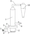
FIG. 1 is a front view of a high efficiency spin flash dryer of the present invention;
FIG. 2 is a front cross-sectional view of a heating cylinder in a high efficiency spin flash dryer of the present invention;
FIG. 3 is a front cross-sectional view of a dryer drum in a high efficiency spin flash dryer of the present invention;
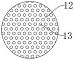
FIG. 4 is a top view of a uniform air plate of a high efficiency spin flash dryer of the present invention;
FIG. 5 is a partial enlarged view of a solid seal ring portion of a high efficiency spin flash dryer of the present invention;
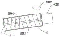
fig. 6 is an internal structure view of a feeding device in a high efficiency spin flash dryer according to the present invention.
The reference numerals are explained below:
1. drying the cylinder body; 2. the motor supports the cylinder; 3. heat dissipation holes; 4. an air inlet cover; 5. a flow guide pipe; 6. heating the cylinder; 7. a blower; 8. a feeding device; 801. a feeding motor; 802. a feed hopper; 803. a feed shaft; 804. a helical blade; 805. a discharge pipe; 9. a material receiving pipe; 10. a cyclone separator; 11. heating wires; 12. a wind homogenizing plate; 13. air holes are formed; 14. a temperature sensor; 15. a wind collecting cavity; 16. an air outlet; 17. rotating the support; 18. a bearing; 19. a sealing groove; 20. a seal ring; 21. a rotating electric machine; 22. a heat dissipating fin; 23. a rotating shaft; 24. a spiral cutter.
Detailed Description
The invention will be further described with reference to the accompanying drawings in which:
as shown in fig. 1-6, an efficient rotary flash dryer comprises a vehicle body, a jaw crusher and a crushing and sorting box body, wherein wheels are connected below the vehicle body through bolts, the jaw crusher is arranged on one side above the vehicle body, a blanking hopper is welded below the jaw crusher, a spiral conveyor is arranged below the blanking hopper, a conveying support is arranged between the spiral conveyor and the vehicle body, the crushing and sorting box body is arranged on one side of the conveying support, a blanking hopper is welded above the crushing and sorting box body, a blanking hopper is welded on one side of the crushing and sorting box body, a first discharge hopper is arranged on the other side wall of the crushing and sorting box body, a second discharge hopper is arranged on one side of the first discharge hopper, a third discharge hopper is arranged on one side of the second discharge hopper, and an internet-of things controller is arranged on one side of the crushing and sorting box body, the novel automatic crushing and sorting device is characterized in that a first crushing support plate is arranged on one side inside the first crushing and sorting box body, a fixed wheel support is arranged above the first crushing support plate, a fixed crushing wheel is arranged inside the fixed wheel support, a first crushing motor is arranged at one end of the fixed crushing wheel, a second crushing support plate is arranged on the other side inside the first crushing and sorting box body, an adjustable support is arranged above the second crushing support plate, an electric push rod is connected between the adjustable support and the crushing and sorting box body, the number of the electric push rod is two, an adjustable crushing wheel is arranged inside the adjustable support, a second crushing motor is arranged at one end of the adjustable crushing wheel, a material guide plate is welded on one side below the second crushing support plate, a filtering screen is arranged below the material guide plate, and the filtering screen comprises a first filtering screen arranged on one side inside the filtering screen, a second filtering screen arranged on one side inside the filtering screen, The filter screen box comprises a first filter screen, a second filter screen, a third filter screen and a handle, wherein the first filter screen is arranged on one side of the first filter screen, the third filter screen is arranged on one side of the second filter screen, the handle is arranged on the side wall of the first filter screen, a material guide box is arranged below the filter screen, and the material guide box comprises a first material guide cavity, a second material guide cavity arranged on one side of the first material guide cavity and a third material guide cavity arranged on one side of the second material guide cavity.
In this embodiment, the drying cylinder 1 is welded to the air inlet cover 4, the air inlet cover 4 is welded to the motor support cylinder 2, the flow guide pipe 5 is connected to the heating cylinder 6 through a flange, and the heating pipe is communicated with the air inlet cover 4 through the flow guide pipe 5, so as to ensure smooth circulation of the drying hot air.
In this embodiment, electric heating wire 11 with heating barrel 6 passes through the screw connection, even aerofoil 12 with heating barrel 6 passes through the draw-in groove and connects, temperature sensor 14 with heating barrel 6 passes through the screw connection, and electric heating wire 11 can be right the inside air base type heating of heating barrel 6, temperature sensor 14 can real-time detection the temperature of heating barrel 6 air outlet, for the output regulation of electric heating wire 11 provides data reference.
In this embodiment, the air inlet cover 4 is in interference fit with the rotating support 17, the rotating shaft 23 is in rolling connection with the rotating support 17 through the bearing 18, and the sealing ring 20 is connected with the rotating shaft 23 and the sealing groove 19 in a clamping and pressing manner, so that the sealing performance of the lower end of the rotating shaft 23 is ensured while the rotating shaft 23 rotates flexibly, and the phenomenon that the rotating flexibility of the rotating shaft 23 is affected due to the fact that small particles are crushed excessively in the drying process and enter between the rotating shaft 23 and the rotating support 17 is avoided.
In this embodiment, the rotating electrical machine 21 with the motor supports barrel 2 and passes through bolted connection, radiator vane 22 with rotating electrical machine 21 passes through the key-type connection, rotating electrical machine 21 starts, can drive radiator vane 22 rotates, and is right rotating electrical machine 21 carries out the forced air cooling heat dissipation, and then does rotating electrical machine 21 cools down, can ensure rotating electrical machine 21 has a good operational environment, and then improves rotating electrical machine 21's life.
In this embodiment, the rotating electrical machines 21 with the rotation axis 23 passes through the key-type connection, the rotation axis 23 with the helical cutting sword 24 passes through the screw connection, the rotating electrical machines 21 starts, can drive the helical cutting sword 24 fast turn, it is right the large granule dry material of drying barrel 1 bottom cuts and smashes, makes it float, carries out the drying to it through hot-blast, can realize carrying out high-efficient drying to dry material.
In this embodiment, the feeding device 8 is welded to the drying cylinder 1, the feeding device has an inclination angle of 5 ° to 10 ° with the horizontal direction, and the feeding device 8 is connected to the feeding motor 801 by screws, so as to ensure that the dried material inside the feeding device 8 can smoothly enter the drying cylinder 1 for drying.
In this embodiment, the feeding shaft 803 is connected with the feeding device 8 in a rolling manner, the feeding shaft 803 is connected with the feeding motor 801 in a key manner, the feeding shaft 803 is welded with the helical blade 804, and the feeding motor 801 is started to drive the feeding shaft 803 and the helical blade 804 to rotate, so that the dry raw material is conveyed.
In this embodiment, the feeding hopper 802 is welded to the feeding device 8, the discharging pipe 805 is welded to the feeding device 8, raw materials to be dried can be fed into the feeding device 8 through the feeding hopper 802, and then dried materials are conveyed to the discharging pipe 805 and discharged into the drying cylinder 1 for drying.
In this embodiment, the drying cylinder 1 is connected with the material receiving pipe 9 through a flange, the material receiving pipe 9 is connected with the cyclone separator 10 through a flange, and the cyclone separator 10 has the same internal structure as an existing cyclone separation device, and is mainly used for separating dried powdery particles from air, so that the separation efficiency of the dried raw materials can be improved.
The specific working principle is as follows: when the drying machine is used, the drying machine is fixedly installed, then the temperature sensor 14, the electric heating wire 11, the rotating motor 21, the feeding motor 801, the air blower 7 and the cyclone separator 10 are connected with an external controller, the output end of a raw material conveying device to be dried is aligned to the feeding hopper 802, firstly, the air blower 7 is started, then external wind is blown into the heating cylinder 6, the electric heating wire 11 in the heating cylinder 6 is rapidly heated with the wind, the wind homogenizing plate 12 plays a role in homogenizing the wind, external wind can be ensured to enter the heating cylinder 6 at a constant speed, the heating stability and consistency can be ensured, the temperature sensor 14 can detect the temperature of the air outlet of the heating cylinder 6 in real time, and data reference is provided for adjusting the output power of the electric heating wire 11, then the hot air in the heating cylinder 6 enters the air inlet cover 4 from the draft tube 5, and is blown out to the inside of the drying cylinder 1 through the air outlet 16 above the air inlet cover 4, the rotating motor 21 is started to drive the heat dissipation blades 22 to rotate, so as to cool the rotating motor 21, so as to ensure that the rotating motor 21 has a good working environment, thereby prolonging the service life of the rotating motor 21, and simultaneously drive the spiral cutting knife 24 to rotate rapidly, cut and crush the large-particle dry substance at the bottom of the drying cylinder 1, so as to float the large-particle dry substance, and dry the large-particle dry substance through the hot air, thereby realizing the high-efficiency drying of the dry substance, the dry substance at the feed hopper 802 can drive the feed shaft 803 and the spiral blades 804 to rotate under the drive of the feed motor 801, the dried material is conveyed to the discharge pipe 805 and discharged into the drying cylinder 1 for drying, in the rotating process of the rotating shaft 23, the bearing 18 can ensure that the rotating shaft 23 can rotate flexibly, the sealing ring 20 can ensure the sealing performance of the lower end of the rotating shaft 23, small particles which are excessively crushed in the drying process are prevented from entering between the rotating shaft 23 and the rotating support 17, the rotating flexibility of the rotating shaft 23 is influenced, the dried material which is dried enters the cyclone separator 10 through the material receiving pipe 9, the dried powdery particles are separated from air through the cyclone separator 10, and the separation efficiency of the dried raw material can be improved.
The foregoing illustrates and describes the principles, general features, and advantages of the present invention. It will be understood by those skilled in the art that the present invention is not limited to the embodiments described above, which are described in the specification and illustrated only to illustrate the principle of the present invention, but that various changes and modifications may be made therein without departing from the spirit and scope of the present invention, which fall within the scope of the invention as claimed.