Active anti-theft electromagnetic lock catch with signal feedback of actuating structure
Technical Field
The invention relates to the technical field of mechanical electromagnetic locks, in particular to an active anti-theft electromagnetic lock catch with an actuating structure and signal feedback.
Background
At present, most of the existing electromagnetic lock structures are electromagnetic lock locks (installed on the upper part of a door), and the electromagnetic lock locks (installed in the inner part of a door frame) are rarely applied. The electromagnetic door lock and the electromagnetic lock catch are different in installation position and have different actuating structures, the electromagnetic door lock emphasizes the actuation of the lock tongue, and the electromagnetic lock catch emphasizes the actuation of the lock catch. In addition, the existing electromagnetic lock has less monitoring on the actuating structure, can not quickly judge whether the electromagnetic lock is unlocked, locked, has faults and the like, and can not meet the application of occasions with higher safety.
Chinese patent (publication No. CN 109653603B, bulletin date 2020.07.14) authorizes a double-redundancy thermal backup actuator electromagnetic lock unlocking and unlocking detection circuit, which comprises a DSP controller and an actuator electromagnetic lock, wherein the unlocking and monitoring circuit comprises two control circuits, two locking and unlocking circuits, two voltage monitoring circuits and two current monitoring circuits. The monitoring circuit can realize unlocking and locking state check and circuit health state evaluation and transmit the unlocking and locking state check and circuit health state evaluation to the remote main control station.
The method has the following defects:
judging whether the electromagnetic lock is unlocked or locked only by judging whether the fed-back voltage or current is within a set threshold range, and easily causing misjudgment when a control circuit is interfered or fails;
secondly, a feasible mechanical structure is not available, and whether the mechanical structure for realizing unlocking or locking is actuated in place cannot be judged;
and thirdly, whether the spring bolt extends into the lock catch or not can not be judged, and potential safety hazards are left.
Therefore, it is necessary to develop an electromagnetic lock catch capable of directly feeding back the position of the actuating structure to determine whether the electromagnetic lock is unlocked or locked, and feeding back whether the coil assembly is normal or not and whether the bolt extends into the lock catch.
Disclosure of Invention
The invention aims to provide an active anti-theft electromagnetic lock catch with an actuating structure and signal feedback, which can directly feed back the position of the actuating structure to judge whether an electromagnetic lock is unlocked or locked without indirectly feeding back whether the electromagnetic lock is unlocked or locked through setting a threshold value by a circuit; and whether the coil assembly is normal or not and whether the lock tongue extends into the lock catch or not can be fed back.
In order to achieve the purpose, the technical scheme of the invention is as follows: the utility model provides an initiative theftproof electromagnetism hasp that signal feedback was followed to actuation structure, its characterized in that: the lock comprises a lock shell component, an electromagnetic transmission component, a lock body transmission component and a lock seat component;
the electromagnetic transmission component is arranged on the lock body transmission component through a screw;
the lock shell assembly and the lock body transmission assembly are both arranged on the lock seat assembly;
the electromagnetic transmission assembly and the lock body transmission assembly are both positioned between the lock shell assembly and the lock seat assembly;
the electromagnetic transmission assembly comprises a magnet box assembly, a cylindrical spiral spring, an armature, a coil supporting frame assembly, a microswitch I, a cable assembly, an actuating rod assembly, a coil assembly and a copper sleeve; the magnet box assembly, the cylindrical spiral spring, the armature, the microswitch I, the cable assembly, the actuating rod assembly, the coil assembly and the copper sleeve are all arranged on the coil supporting frame assembly; the cable assembly is connected with the microswitch I and the coil assembly in a welding mode; when the coil assembly is electrified, a closed magnetic circuit can be formed; when the coil assembly is electrified, the magnet box assembly triggers the micro switch I along with the electromagnetic attraction motion of the armature; when the coil assembly is powered off, the magnet box assembly is separated from contact with the microswitch I under the action of the elastic force of the cylindrical spiral spring; when the coil assembly is in a power-off state, the locking assembly triggers the microswitch II; when the coil assembly is electrified, the locking assembly is separated from being in contact with the microswitch II under the action of the torsion spring II;
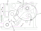
the lock body transmission assembly comprises a torsion spring II, a locking assembly, a safety block assembly, a torsion spring I, a microswitch III, a fixing frame assembly and a microswitch II; the locking assembly, the safety block assembly, the microswitch II and the microswitch III are arranged on the fixed frame assembly; the cable assembly is connected with the micro switch II and the micro switch III in a welding mode; the locking assembly can be switched on or off when moving (both on and off of the microswitch are feedback signals); when the locking assembly moves below the locking transmission rod assembly, the electromagnetic lock catch is locked; when the locking assembly is arranged below the locking transmission rod assembly and props against the locking transmission rod assembly, the propped locking transmission rod assembly limits the movement of the lock catch, and the electromagnetic lock catch is locked; when the locking assembly is separated from the lower part of the locking transmission rod assembly, the limitation of the locking transmission rod assembly is removed, the locking transmission rod assembly can rotate around the axis of the locking transmission rod assembly, when the locking transmission rod assembly can move, the lock catch can also move, and the electromagnetic lock catch is unlocked (as shown in fig. 6, 7 and 8).
The electromagnetic transmission assembly can attract the armature when being electrified, and the magnet box assembly can prop against a microswitch I arranged on the coil support frame assembly when the attraction movement is finished; the actuating rod assembly can be linked with the safety block assembly; the locking assembly can be linked with the locking assembly (as shown in fig. 6-12, the actuating rod assembly and the safety block assembly form a linkage structure, the safety block assembly hooks the actuating rod assembly, the actuating rod assembly moves linearly along with the armature under the action of magnetic force of the coil assembly to drive the safety block assembly to rotate around the axis of the safety block assembly, and the locking assembly is pulled or loosened to complete the linkage action of the actuating rod assembly and the safety block assembly); the safety block assembly can rotate around a shaft and can return to the original position under the action of the torsion spring I; the locking assembly can rotate around a shaft and can return to the original position under the action of the torsion spring II, and a microswitch II is triggered; as shown in fig. 8, when the electromagnetic latch of the present invention is powered off, the armature returns to the original position under the action of the helical cylindrical spring, the actuator rod assembly mounted on the armature pulls back the safety block assembly, and the safety block assembly pulls (pulls back) the locking assembly to complete the unlocking action. When the electromagnetic lock is powered on, the armature moves towards one side of the safety block assembly under the action of magnetic force, so that the safety block assembly rotates around the axis of the safety block assembly, the locking assembly is loosened, the unlocking assembly rotates under the action of the torsion spring II to move to the position below the locking transmission rod assembly, and locking action is completed.
The lock seat assembly comprises a locking transmission rod assembly, a torsion spring IV, a lock catch, a torsion spring III, a bolt transmission assembly, a torsion spring V, a lock seat and a lock catch rod; the locking transmission rod assembly, the torsion spring IV, the lock catch, the torsion spring III, the lock tongue transmission assembly, the torsion spring V and the lock catch rod are all arranged on the lock seat; the locking transmission rod component, the lock catch and the lock tongue transmission component are sequentially arranged from top to bottom; when the lock tongue transmission component moves, the transmission block is transmitted, and the transmission block moves linearly and touches the microswitch III.
In the technical scheme, the microswitch I is arranged at the upper end of the coil supporting frame assembly through a screw;
the coil assembly penetrates through the copper sleeve and is arranged in the coil supporting frame assembly;
the cylindrical spiral spring is arranged on the armature, and the armature is arranged in the coil supporting frame assembly;
the magnet box assembly and the actuating rod assembly are respectively arranged at two sides of the coil support frame assembly; the armature is mounted on the inner face of the coil support frame assembly (the axis of the armature and coil support frame assembly).
One end of the armature is provided with a magnet box component, and the other end is provided with an actuating rod component; the magnet box assembly is arranged at one end of the armature through a screw; the actuating rod component is arranged at the other end of the armature; the magnet box assembly and the actuating rod assembly are both arranged on the outer side surface of the coil supporting frame assembly.
In the technical scheme, a microswitch III and a microswitch II are respectively arranged on two sides of a fixed frame component; the locking assembly is hinged on the fixed frame assembly; the torsion spring II is arranged on the locking assembly and is positioned between the locking assembly and the fixed frame assembly;
the safety block assembly is hinged on the fixed frame assembly and is positioned above the side of the locking assembly; the torsion spring I is installed on the safety block assembly and located between the safety block assembly and the fixing frame assembly.
In the above technical scheme, the lock body transmission assembly further comprises a transmission block, and the transmission block is mounted on the fixed frame assembly and movably connected with the fixed frame assembly;
the transmission block is positioned below the microswitch III (shown in figure 4).
In the technical scheme, a first V-shaped surface is arranged on the transmission block;
a second V-shaped surface is arranged on the lock tongue transmission assembly;
the first V-shaped surface is matched with the second V-shaped surface and is arranged in parallel; when the door is closed, the lock tongue on the door is inserted into the lock catch to prop against the lock tongue transmission assembly, and the lock tongue transmission assembly rotates. The second V-shaped surface of the lock tongue transmission assembly actuates the first V-shaped surface of the transmission block, so that the transmission block moves linearly along the fixed frame assembly to touch the microswitch III;
when the door is opened, the lock tongue on the door leaves the lock catch, is separated from the lock tongue transmission assembly, enables the lock tongue transmission assembly to rotate and return to the original position, the second V-shaped surface of the lock tongue transmission assembly returns to be in a parallel state with the first V-shaped surface of the transmission block, the transmission block is pushed away by a straight line under the action of contact thrust on the microswitch III, and the microswitch III is not touched (as shown in figures 4 and 5).
In the technical scheme, the lock catch is hinged on the lock seat through the lock catch rod and is positioned below the locking transmission rod assembly; the torsion spring III is arranged on the lock catch and is positioned between the lock catch and the lock seat, and the lock catch can rotate around the lock catch rod and can return to the original position under the action of the torsion spring III;
the locking transmission rod assembly is hinged on the lock seat; the torsion spring IV is arranged on the locking transmission rod assembly and is positioned between the locking transmission rod assembly and the lock seat; the locking transmission rod assembly can rotate around a shaft and can return to the original position under the action of the torsion spring IV, and the locking transmission rod assembly can limit and remove the rotation function of the lock catch through rotating around the shaft and returning;
the lock tongue transmission assembly is hinged on the lock seat and positioned below the lock catch side, the torsion spring V is arranged on the lock tongue transmission assembly and positioned between the lock tongue transmission assembly and the lock seat, and when a lock tongue on a door props against or loosens the lock tongue transmission assembly, the lock tongue transmission assembly can rotate; the torsion spring V can enable the lock tongue transmission assembly to return to the original position.
In the technical scheme, the lock shell assembly is a sheet metal part, is arranged on the lock seat through a screw and can fix the cable assembly and protect the internal structure of the active anti-theft electromagnetic lock catch with the signal feedback of the actuating structure.
In the technical scheme, the locking transmission rod assembly and the locking rod are both installed on the lock base through the shaft retainer ring, and the locking transmission rod assembly and the locking rod are limited to be separated from the axial direction of the installation hole of the lock base.
One end of the cylindrical helical spring is abutted against the magnet box assembly, the other end of the cylindrical helical spring is abutted against the coil supporting frame assembly, when the coil assembly is electrified, the armature is attracted, the magnet box assembly arranged on the armature is driven to move towards the direction of the coil supporting frame assembly, and the restoring effect is achieved.
In the technical scheme, a permanent magnet is arranged in the magnet box assembly; energizing the coil assembly with a high level to generate a relatively strong magnetic force, so that the armature moves towards one side of the locking assembly 15 instantly under the action of the magnetic force; the high level can not be switched on for a long time after the movement is finished (the high level is switched on for about 10s, the coil assembly generates heat seriously, and the coil assembly can be burnt out); when the magnetic iron box assembly works for a long time, the low level is used for supplying power to the coil assembly (the low level supplies power to the coil assembly, and the coil assembly does not generate heat), but the low level supplies power to the coil assembly, the generated magnetic force is small, and the cylindrical spiral spring cannot restore the parts such as the armature and the actuating rod assembly arranged on the armature to the original positions, so that the magnetic force is supplemented by the permanent magnet arranged in the magnet box assembly (the permanent magnet in the magnetic iron box assembly has the function of increasing the magnetic force), and the armature and the actuating rod assembly arranged on the armature keep the attraction position under the condition of long-term low level.
The actuating rod assembly, the locking assembly, the safety block assembly and the fixing frame assembly are made of weak magnetic materials or non-magnetic materials, and the problem that transmission of an electromagnetic lock is interfered due to the fact that the actuating rod assembly, the locking assembly, the safety block assembly and the fixing frame assembly are magnetized after the permanent magnet and the coil assembly are electrified is solved.
The coil supporting frame assembly is made of a magnetic conductive material, and is magnetized after being electrified; the magnetized coil supporting frame assembly is attracted with the moving armature and the permanent magnet and the like arranged on the armature, so that the attraction force and the firmness after attraction are enhanced.
The applicant has carried out tests such as vibration tests, impact falling tests, 50kg pendulum impact door body (impact force is transmitted to the electromagnetic lock) and the like of relevant standards of the electromagnetic lock on the invention, and the tests are used for verifying the suction force of the coil assembly, the coil supporting frame assembly, the armature and the permanent magnet and the firmness after attraction under the condition of low level. The invention passes the test verification of vibration test, impact falling test and 50kg pendulum impact door body (the impact force is transmitted to the electromagnetic lock) of the relevant standards of the electromagnetic lock. The tests prove that the low level is adopted to supply power to the coil assembly for a long time, and meanwhile, the magnetic force of the permanent magnet is supplemented, so that the suction force and the firmness after the attraction are reliable.
The invention has the following positive effects:
(1) the feedback signal is generated when the mechanical actuating structure actually moves to the corresponding position, and the feedback signal result is more reliable; a microswitch I is arranged on the electromagnetic transmission assembly and can feed back the actuating state of the electromagnetic transmission assembly to the control system, and the control system can recognize that the electromagnetic transmission assembly works normally; the microswitch II can feed back the actuating state of the locking component to the control system, and the control system can recognize that the electromagnetic lock catch is locked; the microswitch III on the lock body transmission component can feed back the action state of the lock tongue transmission component to the control system, and the control system can identify that the door is opened;
(2) the invention can feed back whether the lock tongue on the door extends into the lock catch, thereby improving the safety;
(3) when the anti-theft lock is unlocked and locked abnormally, the micro switch I, the micro switch II and the micro switch III are switched on and off in an unpredicted logic mode, and a control system can recognize and warn to play an active anti-theft role.
The invention relates to an electromagnetic lock catch with an active anti-theft structure, wherein the active anti-theft function is realized by the signal feedback of a microswitch.
When a monitoring system (in the prior art) monitors abnormal signals of the micro switch, an alarm is started;
when the electromagnetic lock catch is in a standby state (namely, the electromagnetic lock catch is locked for a long time, the monitoring system identifies the states of the three micro switches, the on-off states of the three micro switches are fixed), when a normal request is not made (a violent means), a signal affecting the micro switches is generated, if a door is opened without a normal request, the on-off signal of the micro switch III is identified by the monitoring system, and a corresponding warning (such as an abnormal signal) is sent out; if the electromagnetic lock catch fails to be locked due to violence, the on-off signal of the microswitch II is identified by the monitoring system and corresponding warning is sent out.
Drawings
FIG. 1 is a block diagram of the present invention.
FIG. 2 is a structural diagram of the electromagnetic transmission assembly of the present invention.
Figure 3 is a side view of the transmission assembly of the lock body of the present invention.
Figure 4 is a side view of the lock body transmission assembly of the present invention.
Fig. 5 is a block diagram of the invention.
Fig. 6 is a construction diagram of a locking operation step of the present invention.
Fig. 7 is a structural diagram of an unlocking operation step of the present invention.
Fig. 8 is a schematic view of an unlocking structure of the electromagnetic lock according to the present invention.
Fig. 9 is an enlarged view a of fig. 8.
Fig. 10 is an enlarged view of fig. 8 at a.
Fig. 11 is a schematic structural diagram of a safety block assembly according to the present invention.
FIG. 12 is a schematic view of the actuator assembly of the present invention.
Fig. 13 is a schematic top view of the present invention.
Fig. 14 is a sectional view taken along line a-a of fig. 13.
FIG. 15 is a flow chart of the locking logic of the present invention.
Fig. 16 is a logic flow diagram for unlocking the present invention.
In FIG. 8, E indicates the direction of rotation of the locking assembly, which is rotatable along the arrow of E; f indicates the direction of rotation of the locking drive rod assembly, which can be rotated along the arrow of F.
A in fig. 9 indicates a rotation shaft of the safety block assembly, which rotates about an axis of the rotation shaft a.
In the figure 1-lock shell component, 2-electromagnetic drive component, 3-lock body drive component, 4-lock seat component, 5-magnet box component, 6-cylindrical helical spring, 7-armature, 8-coil supporting frame component, 9-microswitch I, 10-cable component, 11-actuating rod component, 12-coil component, 12.1-main coil component, 12.2-standby coil component, 13-copper sleeve, 14-torsion spring II, 15-locking component, 16-safety block component, 17-torsion spring I, 18-microswitch III, 19-fixing frame component, 20-microswitch II, 21-locking drive rod component, 22-torsion spring IV, 23-lock catch, 24-torsion spring III, 25-lock tongue drive component, 25.1-a second V-shaped surface, 26-a torsion spring V, 27-a locking seat, 28-a locking rod, 29-a transmission block, 29.1-a first V-shaped surface, 101-a screw, 102-a shaft retainer ring I, 103-a shaft retainer ring II, 104-a shaft retainer ring III.
Detailed Description
The embodiments of the present invention will be described in detail with reference to the accompanying drawings, which are not intended to limit the present invention, but are merely exemplary. While the advantages of the invention will be clear and readily understood by the description.
The electromagnetic lock catch integrates the feedback functions of three signals, and the electromagnetic lock catch can give out unlocking and locking signals by generating on-off signals through the micro switch, can feed back whether a lock tongue extends into the lock catch or not, and can also judge whether the coil assembly of the electromagnetic lock catch is normal in function. The invention relates to a structural form of an electromagnetic lock catch arranged on a door upright post. The mechanical actuating structure actually moves to a corresponding position to trigger the microswitch to give unlocking and locking signals, the position of the actuating structure can be directly fed back to judge whether the electromagnetic lock is unlocked or locked, whether the lock tongue extends into the lock catch can be accurately fed back, and the normal function of the coil assembly of the electromagnetic lock catch can also be accurately judged; the defects that whether the electromagnetic lock is unlocked or locked or not is judged by judging whether the voltage or the current fed back is within a set threshold range or not, misjudgment is easy to occur, no feasible mechanical structure exists, and whether the mechanical structure for realizing unlocking or locking is actuated in place or not can not be judged in the prior art are overcome.
As shown in fig. 1, the present invention discloses an active anti-theft electromagnetic lock with signal feedback for an actuation structure, comprising: the lock comprises a lock shell component 1, an electromagnetic transmission component 2, a lock body transmission component 3 and a lock seat component 4. The electromagnetic transmission component 2 is arranged on the lock body transmission component 3 through a screw; after the electromagnetic transmission component 2 is arranged on the lock body transmission component 3, the lock body transmission component 3 is arranged on the lock seat component 4 through a screw; the lock shell component 1 is installed on the lock seat component 4 through screws, and can fix the cable component 10 and protect the internal structures of the electromagnetic transmission component 2, the lock body transmission component 3 and the lock seat component 4.
As shown in fig. 2, the electromagnetic transmission assembly 2 is provided with a coil assembly 12, a copper sleeve 13, a coil support frame assembly 8, an armature 7, a magnet box assembly 5, a cylindrical coil spring 6, an actuating rod assembly 11, a microswitch i 9 and a cable assembly 10. The coil assembly 12 penetrates through the copper sleeve 13 and is arranged on the coil supporting frame assembly 8; the cylindrical coil spring 6 is mounted on the armature 7 and then mounted together on the coil support frame assembly 8; the magnet box assembly 5 is arranged at one end of the armature 7 through a screw; the actuating rod component 11 is arranged at the other end of the armature 7; the microswitch I9 is arranged on the coil supporting frame assembly 8 through a screw; the cable assembly 10 is connected with the coil assembly 12 and the microswitch I9 in a welding mode.
As shown in fig. 3, a fixing frame assembly 19, a locking assembly 15, a safety block assembly 16, a micro switch ii 20, a micro switch iii 18, a torsion spring ii 14 and a torsion spring i 17 are arranged in the lock body transmission assembly 3. The electromagnetic transmission component 2, the locking component 15, the safety block component 16, the micro switch II 20 and the micro switch III 18 are arranged on the fixed frame component 19; a permanent magnet is arranged in the magnet box component 5 for increasing magnetism; the electromagnetic transmission component 2 can attract the armature 7 when being electrified, the magnet box component 5 can prop against a microswitch I9 arranged on the coil supporting frame component 8 when the attracting motion is finished, and meanwhile, the armature 7 can prop against the coil supporting frame component 8; the actuating rod assembly 11 can be linked with the safety block assembly 16; the safety block assembly 16 can be linked with the locking assembly 15; the safety block component 16 can rotate around a shaft and can return to the original position under the action of a torsion spring I17; the locking assembly 15 can rotate around a shaft and can return to the original position under the action of the torsion spring II 14, and a microswitch II 20 is triggered; and the micro switch II 20 and the micro switch III 18 are connected with the cable assembly 10 in a welding mode.
As shown in fig. 4, the driving block 29 can move linearly to trigger the microswitch iii 18.
As shown in fig. 5, the lock seat assembly 4 is provided with a lock seat 27, a lock catch 23, a lock catch lever 28, a lock transmission lever assembly 21, a torsion spring iii 24, a torsion spring iv 22, a torsion spring v 26 and a bolt transmission assembly 25. The lock catch 23 is arranged on the lock seat 27 through a lock catch rod 28, and the lock catch 23 can rotate around the lock catch rod 28 and can return to the original position under the action of the torsion spring III 24; the torsion spring IV 22 is arranged on the locking transmission rod component 21 and then is arranged on the lock seat 27 together; the locking transmission rod assembly 21 can rotate around a shaft and can return to the original position under the action of the torsion spring IV 22; the locking transmission rod assembly 21 can limit and release the rotation function of the lock catch 23; the bolt transmission assembly 25 is arranged on the lock seat 27, and when the bolt on the door props or loosens the bolt transmission assembly 25, the bolt transmission assembly 25 can rotate; the torsion spring v 26 is able to return the deadbolt drive assembly 25 to the home position.
The shaft retainer ring comprises a shaft retainer ring I102, a shaft retainer ring II 103 and a shaft retainer ring III 104.
The locking transmission rod assembly 21 is arranged on the lock seat 27 through a shaft retainer ring I102;
two ends of the lock catch rod 28 are respectively installed on the lock base 27 through a shaft retaining ring II 103 and a shaft retaining ring III 104, and the lock catch rod 28 is limited to be separated from the axial direction of the installation hole of the lock base.
The invention has three microswitches, three signal feedbacks are provided, which are respectively the signal feedback of whether the coil component is normal, the signal feedback of unlocking and the signal feedback of opening and closing the door; the three signal feedback modes are as follows:
1) signal feedback whether the coil assembly is normal: the microswitch I9 arranged on the coil supporting frame assembly 8 can judge whether the coil assemblies (as shown in figures 1 and 2, two coil assemblies 12 are respectively a main coil assembly 12.1 and a standby coil assembly 12.2, the main coil assembly 12.1 and the standby coil assembly 12.2 are both arranged on the coil supporting frame assembly 8, the main coil assembly 12.1 and the standby coil assembly 12.2 are both provided with thermal protection resistors and are independent of each other, when the main coil assembly 12.1 fails, the standby coil assembly 12.2 can be in relay locking in a low level state, the main coil assembly 12.1 generates heat, when electromagnetic attraction is reduced, the state and the use of the standby coil assembly are not influenced, the high-level to low-level power switching time is within 1s, the main coil assembly 12.1 can realize the function in the normal locking working step, when the main coil assembly 12.1 is switched to the standby coil assembly within 300 milliseconds, the standby coil assembly 12.2 can realize the relay locking function of the invention), after the coil component is electrified, electromagnetic force is generated to attract the armature 7 and the magnet box component 5 arranged on the armature 7, the magnet box component 5 triggers the microswitch I9, if the coil component cannot generate magnetic force after being electrified (the damage of the coil component is indicated), the magnet box component 5 cannot trigger the microswitch I9, a signal of the microswitch I9 is abnormal (namely the signal is not in accordance with the preset logic of a monitoring system, the preset logic of the monitoring system is shown in figures 15 and 16), and the monitoring system identifies (the monitoring system is the prior art);
2) unlocking and unlocking signal feedback: install micro-gap switch II 20 in mount subassembly 19 one side and can direct feedback and actuate the structure position and judge whether the electromagnetic lock unblanks or locks, the principle is: when the electromagnetic lock catch is powered on, the locking assembly 15 is hinged to the fixed frame assembly 19 and rotates to move, when the locking assembly leaves the micro switch II 20, a locking signal is obtained, and meanwhile the locking assembly moves to the position below the locking transmission rod assembly 21, at the moment, the locking assembly 15 abuts against the locking transmission rod assembly 21 (namely, the locking transmission rod assembly 21 is limited), when the locking transmission rod assembly 21 abuts against, the lock catch 23 is also fixed by being locked, and the lock catch 23 is fixed, namely, the electromagnetic lock catch is locked (the locking logic is shown in figure 15);
on the contrary, after the power is cut off, the locking assembly 15 returns to the original position under the action of the torsion spring II 14, the micro switch II 20 is triggered, an unlocking signal can be obtained, the limit of the locking transmission rod assembly 21 is released, and the electromagnetic lock catch is unlocked (the unlocking logic is shown in figure 16).
3) And (3) door opening and closing signal feedback: the microswitch III 18 can feed back whether the door is closed or not; the principle is as follows: when the door is closed, the bolt on the door props against the bolt transmission component 25 of the electromagnetic lock, the second V-shaped surface 25.1 of the bolt transmission component 25 pushes the first V-shaped surface 29.1 on the transmission block 29 to make the bolt transmission component move linearly, the micro switch III 18 is triggered, and the electromagnetic lock feeds back a door closing signal to be identified by a monitoring system. Otherwise, the bolt on the door is separated from the bolt transmission assembly 25 of the electromagnetic lock, the switch button of the microswitch III 18 rebounds, and the electromagnetic lock feeds back a door opening signal to be identified by the monitoring system.
Therefore, the invention has the capability of feeding back whether the electromagnetic lock coil assembly is normal or not, feeding back whether the electromagnetic lock is unlocked or locked or not, and feeding back whether the door is closed or not.
As shown in fig. 1 to 12, the working steps of the active anti-theft electromagnetic lock with signal feedback in the actuating structure according to the present invention are as follows:
1) and locking the working step:
when the door is closed, the door latch bolt is inserted into the buckle 23, and abuts against the latch bolt driving assembly 25, and the latch bolt driving assembly 25 is rotated. The second V-shaped surface 25.1 of the bolt transmission component 25 actuates the V-shaped surface of the transmission block 29, so that the transmission block 29 moves linearly to touch the microswitch III 18, the microswitch III 18 generates an on-off signal to the control system, the control system can identify that the bolt on the door is inserted into the lock catch 23, the control system (namely the monitoring system) energizes the coil component 12 according to the preset logic (the preset locking logic of the control system is shown in figure 15), the coil component 12 forms a closed magnetic circuit under the action of the coil support frame component 8, overcomes the elastic force of the cylindrical spiral spring 6, attracts the armature 7 and the magnet box component 5 to move towards the coil component 12, until the armature 7 props against the coil support frame component 8, the magnetic attracting movement generated by the coil component 12 is finished, at the moment, the magnet box component 5 triggers the microswitch I9 along with the movement of the armature 7, and the microswitch I9 generates an on-off signal to the microswitch I9, the control system can recognize that the coil assembly 12 is operating properly. The actuating rod assembly 11 moves towards the coil assembly 12 along with the armature 7 in the attracting process and is linked with the safety block assembly 16, and at the moment, the safety block assembly 16 is separated from the locking assembly 15 under the action of the torsion spring I17 and is located at a position where the safety block assembly abuts against the locking assembly 15, so that the safety function is achieved. When the locking assembly 15 rotates around the shaft to the lower part of the locking transmission rod assembly 21 under the action of the torsion spring II 14, the locking assembly 15 is just limited by the fixed frame assembly 19 to move, at the moment, the locking assembly 15 is separated from the microswitch II 20, the microswitch II 20 generates an on-off signal to be sent to the control system, and the control system can recognize that the locking assembly 15 works normally. The locking transmission rod assembly 21 can only be limited to the rotation movement direction of the locking assembly 15, when the locking transmission rod assembly 21 is limited to the locking assembly 15, the rotation movement direction of the lock catch 23 is also limited by the locking transmission rod assembly 21, and the active anti-theft electromagnetic lock catch with signal feedback is locked in the actuating structure.
2) And unlocking the lock:
when the door needs to be opened, the coil assembly 12 is powered off, the armature 7 returns to the original position under the elastic force action of the cylindrical spiral spring 6, the magnet box assembly 5 moves along with the armature 7 to leave the microswitch I9, the microswitch I9 generates an on-off signal to the control system, the control system can recognize that the coil assembly 12 stops working, and the control system (namely the monitoring system) powers off the coil assembly 12 according to preset logic (the preset unlocking logic of the control system is shown in figure 16). The actuating rod assembly 11 arranged on the armature 7 is linked with the safety block assembly 16, the safety block assembly 16 is linked with the locking assembly 15, the locking assembly 15 is separated from the lower part of the locking transmission rod assembly 21, and the rotation limitation of the locking transmission rod assembly 21 is removed. Accordingly, the rotation restriction of the lock 23 by the lock transmission lever assembly 21 is also released. Along with the fact that the locking assembly 15 leaves the lower portion of the locking transmission rod assembly 21, the micro switch II 20 generates an on-off signal to the control system, the control system can recognize that the active anti-theft electromagnetic lock catch with the signal feedback of the actuating structure is in an unlocking state, operations such as door handle rotation and key insertion unlocking are not needed, and the door can be opened when being pushed.
3) And door opening signal feedback:
when the door is opened, the lock tongue on the door leaves the lock catch 23 and is separated from the lock tongue transmission assembly 25, the lock tongue transmission assembly 25 is rotated and returned to the original position, the second V-shaped surface 25.1 of the lock tongue transmission assembly 25 is returned to be parallel to the first V-shaped surface 29.1 of the transmission block 29, the transmission block 29 is pushed away linearly under the action of contact thrust on the micro switch III 18, the micro switch III 18 is not touched, the micro switch III 18 generates an on-off signal to the control system, and the control system can recognize that the door is opened.
It should be noted that the control system recognizes the on/off signal and is easy to be powered on and off according to the preset logic, and therefore, the detailed description thereof is omitted.
Other parts not described belong to the prior art.