CN113426556B - Purification and grinding equipment for waste and impurity discharge - Google Patents
Purification and grinding equipment for waste and impurity discharge Download PDFInfo
- Publication number
- CN113426556B CN113426556B CN202110984973.3A CN202110984973A CN113426556B CN 113426556 B CN113426556 B CN 113426556B CN 202110984973 A CN202110984973 A CN 202110984973A CN 113426556 B CN113426556 B CN 113426556B
- Authority
- CN
- China
- Prior art keywords
- grinding
- crushing
- screening
- connecting rod
- impurities
- Prior art date
- Legal status (The legal status is an assumption and is not a legal conclusion. Google has not performed a legal analysis and makes no representation as to the accuracy of the status listed.)
- Active
Links
Images


Classifications
-
- B—PERFORMING OPERATIONS; TRANSPORTING
- B02—CRUSHING, PULVERISING, OR DISINTEGRATING; PREPARATORY TREATMENT OF GRAIN FOR MILLING
- B02C—CRUSHING, PULVERISING, OR DISINTEGRATING IN GENERAL; MILLING GRAIN
- B02C21/00—Disintegrating plant with or without drying of the material
-
- B—PERFORMING OPERATIONS; TRANSPORTING
- B02—CRUSHING, PULVERISING, OR DISINTEGRATING; PREPARATORY TREATMENT OF GRAIN FOR MILLING
- B02C—CRUSHING, PULVERISING, OR DISINTEGRATING IN GENERAL; MILLING GRAIN
- B02C18/00—Disintegrating by knives or other cutting or tearing members which chop material into fragments
- B02C18/0084—Disintegrating by knives or other cutting or tearing members which chop material into fragments specially adapted for disintegrating garbage, waste or sewage
-
- B—PERFORMING OPERATIONS; TRANSPORTING
- B02—CRUSHING, PULVERISING, OR DISINTEGRATING; PREPARATORY TREATMENT OF GRAIN FOR MILLING
- B02C—CRUSHING, PULVERISING, OR DISINTEGRATING IN GENERAL; MILLING GRAIN
- B02C18/00—Disintegrating by knives or other cutting or tearing members which chop material into fragments
- B02C18/06—Disintegrating by knives or other cutting or tearing members which chop material into fragments with rotating knives
- B02C18/08—Disintegrating by knives or other cutting or tearing members which chop material into fragments with rotating knives within vertical containers
- B02C18/10—Disintegrating by knives or other cutting or tearing members which chop material into fragments with rotating knives within vertical containers with drive arranged above container
-
- B—PERFORMING OPERATIONS; TRANSPORTING
- B02—CRUSHING, PULVERISING, OR DISINTEGRATING; PREPARATORY TREATMENT OF GRAIN FOR MILLING
- B02C—CRUSHING, PULVERISING, OR DISINTEGRATING IN GENERAL; MILLING GRAIN
- B02C18/00—Disintegrating by knives or other cutting or tearing members which chop material into fragments
- B02C18/06—Disintegrating by knives or other cutting or tearing members which chop material into fragments with rotating knives
- B02C18/16—Details
- B02C18/18—Knives; Mountings thereof
-
- B—PERFORMING OPERATIONS; TRANSPORTING
- B02—CRUSHING, PULVERISING, OR DISINTEGRATING; PREPARATORY TREATMENT OF GRAIN FOR MILLING
- B02C—CRUSHING, PULVERISING, OR DISINTEGRATING IN GENERAL; MILLING GRAIN
- B02C18/00—Disintegrating by knives or other cutting or tearing members which chop material into fragments
- B02C18/06—Disintegrating by knives or other cutting or tearing members which chop material into fragments with rotating knives
- B02C18/16—Details
- B02C18/24—Drives
-
- B—PERFORMING OPERATIONS; TRANSPORTING
- B02—CRUSHING, PULVERISING, OR DISINTEGRATING; PREPARATORY TREATMENT OF GRAIN FOR MILLING
- B02C—CRUSHING, PULVERISING, OR DISINTEGRATING IN GENERAL; MILLING GRAIN
- B02C19/00—Other disintegrating devices or methods
- B02C19/10—Mills in which a friction block is towed along the surface of a cylindrical or annular member
-
- B—PERFORMING OPERATIONS; TRANSPORTING
- B02—CRUSHING, PULVERISING, OR DISINTEGRATING; PREPARATORY TREATMENT OF GRAIN FOR MILLING
- B02C—CRUSHING, PULVERISING, OR DISINTEGRATING IN GENERAL; MILLING GRAIN
- B02C23/00—Auxiliary methods or auxiliary devices or accessories specially adapted for crushing or disintegrating not provided for in preceding groups or not specially adapted to apparatus covered by a single preceding group
- B02C23/08—Separating or sorting of material, associated with crushing or disintegrating
- B02C23/14—Separating or sorting of material, associated with crushing or disintegrating with more than one separator
-
- B—PERFORMING OPERATIONS; TRANSPORTING
- B02—CRUSHING, PULVERISING, OR DISINTEGRATING; PREPARATORY TREATMENT OF GRAIN FOR MILLING
- B02C—CRUSHING, PULVERISING, OR DISINTEGRATING IN GENERAL; MILLING GRAIN
- B02C2201/00—Codes relating to disintegrating devices adapted for specific materials
- B02C2201/06—Codes relating to disintegrating devices adapted for specific materials for garbage, waste or sewage
Abstract
The invention relates to the field of crushing and screening, in particular to a purification and grinding device for waste and impurity discharge. Impurities which cannot be fully ground in the primary grinding cavity are increased, so that the first vertical edge moves outwards under the action of the outward pushing force of the impurities on the inner side of the screening plate, the area of the screening hole is increased, the volume of the primary grinding cavity is increased, and the included angle between the sliding connecting rod group and the screening plate is increased; one side of the sliding connection group facing the screening plate is used for guiding impurities to enter the secondary grinding cavity through the screening holes; the impurity that the chamber was not ground is ground to the second grade increases, makes the screening plate outside receive the inside thrust effect of impurity to inside removal down to the realization is grinding crushing in-process, further reduces the device and grinds obstructed time, and then improves grinding efficiency.
Description
Technical Field
The invention relates to the field of crushing and screening, in particular to a purification and grinding device for waste and impurity discharge.
Background
Present cutting breaker is cutting broken in-process to impurity, when meetting the great impurity of diameter, cutting breaker can not directly effectually fully cut the breakage with impurity, consequently along with leading-in to cutting the garrulous device that impurity lasts, impurity in the device can be more and more, it can make cutting breaker's rotation be obstructed until the card dies to gather impurity, this kind of condition just needs the stop equipment to carry out manual operation, will block dead part and dredge, like this will greatly reduced the broken efficiency of cutting, personnel's cost input has also been increased.
Disclosure of Invention
The invention provides a purification and grinding device for waste and impurity discharge, which aims to solve the problem that the existing cutting and crushing device is low in efficiency and easy to block.
The invention discloses a purification and grinding device for waste and impurity discharge, which adopts the following technical scheme:
the purifying and grinding equipment for waste and impurity discharge comprises a grinding barrel, a plurality of crushing plates, a plurality of sliding connecting rod groups, a driving connecting mechanism and a grinding column; the crushing plates are positioned in the grinding barrel and are uniformly distributed along the circumferential direction of the grinding barrel, and each crushing plate comprises a screening plate and a crushing tooth group; the screening plates are rectangular plate-shaped and are vertically arranged, two vertical edges of each screening plate are respectively a first vertical edge and a second vertical edge, the first vertical edge of each screening plate is contacted with the inner side surface of one adjacent screening plate, the second vertical edge is positioned at the outer side of the other adjacent screening plate, and the crushing tooth group is arranged on the second vertical edge and is used for being matched with the grinding barrel to crush impurities on the outer sides of the screening plates; the screening plate is provided with a plurality of screening holes extending along the horizontal direction, and each screening hole extends along the horizontal direction; each sliding connecting rod group comprises a plurality of sliding connecting rods which are sequentially arranged up and down, and the outer end of each sliding connecting rod is rotatably arranged on a second vertical edge; each sliding connecting rod is slidably arranged on one first vertical edge along the length direction of the sliding connecting rod, and when the first vertical edge slides outwards along the inner side face of the corresponding screening plate, the included angle between the sliding connecting rod group and the screening plate is increased, and the area of the screening hole is increased; a crushing cutter group is arranged at the inner end of each sliding connecting rod group; the plurality of crushing plates and the plurality of sliding linkages constitute a crushing ring. The driving connection mechanism is configured to drive the plurality of crushing plates to synchronously rotate in the grinding barrel; the grinding column is vertically arranged at the axis of the crushing ring, and the crushing ring divides the space between the grinding column and the grinding barrel into a primary grinding cavity at the inner side and a secondary grinding cavity at the outer side; impurities which cannot be fully ground in the primary grinding cavity are increased, so that the first vertical edge moves outwards under the action of the outward pushing force of the impurities on the inner side of the screening plate, the area of the screening hole is increased, the volume of the primary grinding cavity is increased, and the included angle between the sliding connecting rod group and the screening plate is increased; one side of the sliding connecting rod group facing the screening plate is used for guiding impurities to enter the secondary grinding cavity through the screening hole; the impurity that the second grade grinding chamber was not ground increases, makes the screening plate outside receive the inward thrust of impurity effect down inwards to remove.
Furthermore, the sliding connecting rod is in a long rod shape, the outer end of the sliding connecting rod is provided with a hinge hole, and the sliding connecting rod is rotatably arranged on the second vertical edge through the hinge hole; the sliding connecting rod is provided with a waist-shaped groove, and the first vertical edge can be slidably arranged on the waist-shaped groove.
Further, a crushing knife group comprises a plurality of crushing knives, each crushing knife is arranged at the inner end of one sliding connecting rod, the cutting edge of each crushing knife is smoothly connected with the edge of the inner end of the sliding connecting rod, so that a material guide surface is formed between the cutting edges of the crushing knives and the sliding connecting rods, and impurities are guided to pass through the screening holes from the inner side of the screening plate to the outer side of the screening plate.
Furthermore, the upper end surface of the grinding column is a spherical surface with an upward convex axis; a plurality of crushing column knife groups are uniformly distributed on the peripheral wall of the grinding column along the axial direction; each crushing column knife group comprises a plurality of crushing column knives, one end of each crushing column knife is fixed on the peripheral wall of the grinding column, the other end of each crushing column knife extends outwards, and a cutting edge extends out of the left side surface of each crushing column knife; each crushing column knife corresponds to the interval between two adjacent crushing knives and is configured to cut and crush impurities inside the crushing plate.
Furthermore, the crushing tooth group comprises a plurality of crushing teeth, each crushing tooth is a semicircular tooth, one end of the circular arc extends outwards, and the other end of the circular arc is fixed on the second vertical edge; a plurality of crushing teeth are uniformly distributed on the second vertical edge at intervals in the vertical direction; a plurality of grinding tooth groups are uniformly distributed on the inner wall of the grinding barrel along the axial direction; each grinding tooth group comprises a plurality of grinding teeth, each grinding tooth is a semicircular tooth, one end of the circular arc extends outwards, the other end of the circular arc is fixed on the peripheral wall, and each crushing tooth penetrates between two grinding teeth.
Further, the width of the screening holes at the end near the first vertical edge is smaller than the width at the end near the second vertical edge.
Further, the driving connection structure comprises a driving mechanism and a connection mechanism; the driving mechanism comprises a motor and a sliding column sleeve; the sliding column sleeve is slidably and rotatably arranged in the grinding barrel, and the motor is configured to drive the sliding column sleeve to rotate through the transmission mechanism; the connecting mechanism comprises a plurality of driving connecting rods and a plurality of hinged parts; the plurality of hinged parts are uniformly distributed at the lower end of the sliding column sleeve in the circumferential direction; each drive link is hinged at an upper end to one of the hinge portions and at a lower end to an upper end of one of the first vertical edges.
Further, the purification and grinding equipment for the waste and impurity discharge also comprises a feeding mechanism; the feeding mechanism comprises a feed hopper and a material guide pipe; the feed hopper is funnel-shaped, the bottom of the feed hopper is provided with a discharge hole, and the feed hopper is fixedly arranged at an opening at the upper end of the grinding barrel; the material guide pipe comprises a straight pipe and a conical pipe; the straight pipe is vertically arranged, and the upper end of the straight pipe is fixedly connected with the discharge port and is used for communicating with the feed hopper; the diameter of the lower end of the conical pipe is larger than that of the upper end of the conical pipe, the upper end opening of the conical pipe is fixedly connected with the lower end of the straight pipe, the lower end of the conical pipe is fixedly connected to the upper end of the grinding column, the spherical surface of the conical pipe extends into the conical pipe, and a material guide opening is formed between the conical pipe and the grinding column, so that impurities in the material guide pipe enter the primary grinding cavity from the material guide opening.
Further, the transmission mechanism comprises a driving wheel and a driven wheel; the driven wheel can be rotatably arranged in the grinding barrel through a bracket; the sliding column sleeve can be inserted in the driven wheel in a vertical sliding manner; the motor base is fixedly arranged on the lower surface of the feed hopper, and an output shaft of the motor extends downwards; the driving wheel is fixedly arranged on an output shaft of the motor and is connected with the driven wheel through a transmission belt.
A purification and grinding process for waste and impurity discharge comprises the following steps:
s1, introducing the waste into a purification grinding device for grinding and purification treatment;
s2, turning on a motor to drive a crushing ring to rotate, grinding impurities by the crushing ring, pushing the screening plate to the outer side when the rotation of the crushing ring is blocked due to the impurities, and increasing the volume of a primary grinding cavity to enlarge the movable space of the impurities, wherein the screening plate is pushed to the outer side by the impurities and is subjected to the outward thrust;
and S3, reducing the volume of the secondary grinding cavity, so that the crushing teeth gradually penetrate into the space between two adjacent grinding wall teeth, further grinding the impurities entering the secondary grinding cavity, fully grinding the crushed impurities, and screening by using a screening mesh screen.
And S4, recovering and intensively treating the materials after evolution and grinding through a recovery device.
The invention has the beneficial effects that: according to the purification and grinding equipment for the waste and impurity discharge, the rotation of the crushing ring is blocked due to the accumulation of impurities in the primary grinding cavity, the screening plate is pushed outwards by the impurities, the screening plate is pushed outwards, the size of the primary grinding cavity is increased, the movement space of the impurities is increased, and the effect of eliminating the rotation resistance is achieved. Simultaneously first vertical edge is outside along corresponding screening inboard, makes the screening hole area increase, the also corresponding grow of volume of accessible impurity, again because the contained angle grow gradually between this in-process and corresponding screening board of sliding linkage group, so sliding linkage group has the guide effect to impurity through the screening hole, improves impurity and passes through screening hole speed. Because first vertical edge outwards slides along corresponding screening inboard, the volume in second grade grinding chamber reduces to the impurity that makes and then the second grade grinding intracavity is ground the breakage once more, has realized abundant high-efficient broken effect.
Drawings
In order to more clearly illustrate the embodiments of the present invention or the technical solutions in the prior art, the drawings used in the description of the embodiments or the prior art will be briefly described below, and it is obvious that the drawings in the following description are only some embodiments of the present invention, and for those skilled in the art, other drawings can be obtained according to these drawings without creative efforts.
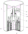
FIG. 1 is a sectional view of an embodiment of a waste effluent purification mill apparatus of the present invention;
FIG. 2 is an enlarged view of a portion of FIG. 1 at A;
FIG. 3 is a schematic view of the crushing ring of an embodiment of the apparatus for purifying and grinding the waste and impurities discharge according to the present invention;
FIG. 4 is an enlarged view of a portion of FIG. 3 at B;
FIG. 5 is a top plan view of a breaker ring of an embodiment of the apparatus for the clean-up grinding of waste material of the present invention;
FIG. 6 is a fragmentary top plan view of a crushing ring of an embodiment of the apparatus for the clean-up grinding of waste effluent of the present invention;
FIG. 7 is a partial perspective view of a crushing ring of an embodiment of the apparatus for the purification and grinding of waste effluent of the present invention;
FIGS. 8 and 9 are schematic views showing the operation of an embodiment of the waste material purifying and grinding apparatus according to the present invention;
FIG. 10 is a schematic view of a polishing column of an embodiment of the waste effluent purifying polishing apparatus according to the present invention;
in the figure: 111. a feed hopper; 112. an inner wall; 113. grinding the column; 114. a straight pipe; 115. a material guide port; 116. a tapered tube; 117. crushing a cylindrical cutter; 12. a motor; 13. a transmission belt; 14. a drive link; 15. a sliding column sleeve; 151. a spline; 152. a hinge ring; 16. a driven wheel; 20. a crushing ring; 201. crushing teeth; 202. a spherical hinge button; 203. a material guiding surface; 204. a crushing knife; 205. a screening well; 206. screening the plate; 207. a waist-shaped groove; 30. and (4) screening the net.
Detailed Description
The technical solutions in the embodiments of the present invention will be clearly and completely described below with reference to the drawings in the embodiments of the present invention, and it is obvious that the described embodiments are only a part of the embodiments of the present invention, and not all of the embodiments. All other embodiments, which can be derived by a person skilled in the art from the embodiments given herein without making any creative effort, shall fall within the protection scope of the present invention.
One embodiment of the present invention, as shown in fig. 1-10, further includes a plurality of crushing plates, a plurality of sliding linkages, a drive linkage, and a grinding column 113. A plurality of breaker plates are located the grinding barrel, and along the circumference equipartition setting of grinding barrel, every breaker plate includes screening plate 206 and broken tooth 201 group. The screening plate 206 is rectangular plate-shaped and vertical setting, and two vertical edges of every screening plate 206 are first vertical edge and second vertical edge respectively, and the first vertical edge of every screening plate 206 contacts with the medial surface of an adjacent screening plate 206, and the second vertical edge is in the outside of another adjacent screening plate 206, and broken tooth 201 group sets up on the second vertical edge for with the impurity in the grinding barrel cooperation breakage screening plate 206 outside. The screening plate 206 is provided with a plurality of screening holes 205 extending in the horizontal direction, and each screening hole 205 extends in the horizontal direction. Each sliding connecting rod group comprises a plurality of sliding connecting rods which are sequentially arranged from top to bottom, and the outer end of each sliding connecting rod is rotatably arranged on one second vertical edge. Each sliding link is slidably mounted along its length on a first vertical edge, and when the first vertical edge slides outward along the inner side of the corresponding screening plate 206, the included angle between the sliding link group and the screening plate 206 increases, and the area of the screening hole 205 increases. The sliding connecting rod is in a long rod shape, the outer end of the sliding connecting rod is provided with a hinge hole, and the sliding connecting rod is rotatably arranged on the vertical edge of the second through the hinge hole. The sliding connecting rod is provided with a waist-shaped groove 207, and the first vertical edge can be slidably arranged on the waist-shaped groove 207. A crushing knife 204 group is arranged on the inner side of each sliding connecting rod group; the plurality of crushing plates and the plurality of sliding linkages constitute a crushing ring 20. The drive connection mechanism is configured to drive the plurality of crushing plates to synchronously rotate in the grinding barrel. The grinding column 113 is vertically arranged at the axis of the crushing ring 20, and the crushing ring 20 divides the space between the grinding column 113 and the grinding barrel into a primary grinding cavity at the inner side and a secondary grinding cavity at the outer side. The impurity that the intracavity can not fully grind is ground to the one-level increases, makes first vertical edge receive outside removal under the effect of the outside thrust of impurity at screening plate 206 inboard, and screening hole 205 area grow, and the chamber volume grow is ground to the one-level, and the contained angle grow between sliding linkage and the screening plate 206 is ground to the one-level simultaneously. The side of the sliding linkage facing the screen plate 206 serves to guide impurities through the screen apertures 205 into the secondary grinding chamber. The secondary grinding chamber is more unground and the outside of the screening plate 206 is forced by the inward pushing force of the impurities to move inward. The grinding barrel base is provided with a screening net 30, and a grinding column 113 is fixed on the screening net 30. The number of the crushing plates is six.
In the present embodiment, as shown in fig. 3 to 7, one crushing blade 204 set includes a plurality of crushing blades 204, each crushing blade 204 is installed at the inner end of one sliding connecting rod, the cutting edge of each crushing blade 204 is smoothly connected with the edge of the inner end of the sliding connecting rod, so that a material guiding surface 203 is formed between the cutting edges of the plurality of crushing blades 204 and the plurality of sliding connecting rods, so as to guide impurities from the inner side of the screening plate 206 to the outer side of the screening plate 206 through the screening holes 205, when the included angle between the sliding connecting rod set and the screening plate 206 is increased, the material guiding surface 203 can further improve the efficiency and speed of the impurities passing through the screening holes 205, thereby shortening the rotation blocking time.
In the present embodiment, as shown in fig. 1 and 10, the upper end surface of the grinding pillar 113 is a spherical surface whose axis is convex upward; a plurality of crushing cylinder blade 117 sets are uniformly distributed on the circumferential wall of the grinding cylinder 113 along the axial direction. Each crushing cylinder blade 117 group comprises a plurality of crushing cylinder blades 117, one end of each crushing cylinder blade 117 is fixed on the peripheral wall of the grinding cylinder 113, the other end of each crushing cylinder blade 117 extends outwards, and a cutting edge extends from the left side surface of each crushing cylinder blade 117, so that the cutting edge cuts and crushes impurities when the crushing ring 20 rotates anticlockwise. Each crushing cylinder blade 117 corresponds to the interval between two adjacent crushing blades 204, so that the crushing cylinder blades 117 and the crushing blades 204 in the primary grinding cavity are matched with each other to cut and crush impurities in the primary grinding cavity.
In the present embodiment, as shown in fig. 3 to 7, the crushing teeth 201 set includes a plurality of crushing teeth 201, each crushing tooth 201 is a semicircular tooth, one end of the arc extends outwards, the other end is fixed on the second vertical edge, the crushing tooth 201 is located at the outermost end and does not contact with the grinding wall, and the arc is configured to prevent the crushing tooth 201 and the grinding wall from being jammed by impurities. A plurality of crushing teeth 201 are evenly spaced in the vertical direction on the second vertical edge. A plurality of grinding tooth groups are uniformly distributed on the inner wall 112 of the grinding barrel along the axial direction; each grinding tooth group comprises a plurality of grinding teeth, each grinding tooth is a semicircular tooth, one end of an arc extends outwards, the other end of the arc is fixed on the peripheral wall, and each crushing tooth 201 is used for penetrating between two grinding teeth.
In the present embodiment, as shown in fig. 7, the width of the screening hole 205 at an end near the first vertical edge is smaller than the width at an end near the second vertical edge. The first vertical edges are slid outward along the corresponding screening plates 206, and the height of the screening holes 205 in the vertical direction becomes larger, and the volume of passing impurities becomes larger.
In the present embodiment, as shown in fig. 1, a purification and grinding apparatus for waste and impurity discharge further includes a feeding mechanism; the feeding mechanism includes a feeding hopper 111 and a guide tube. The feed hopper 111 is funnel-shaped, a discharge hole is formed in the bottom of the feed hopper 111, and the feed hopper 111 is fixedly arranged at an opening at the upper end of the grinding barrel; the guide tubes include a straight tube 114 and a tapered tube 116; the straight pipe 114 is vertically arranged, and the upper end of the straight pipe is fixedly connected with the discharge port and is used for being communicated with the feed hopper 111; the diameter of the lower end of the conical tube 116 is larger than that of the upper end, the opening of the upper end is fixedly connected with the lower end of the straight tube 114, the lower end of the conical tube 116 is fixedly connected with the upper end of the grinding column 113, the spherical surface extends into the conical tube 116, and a material guiding opening 115 is arranged between the conical tube 116 and the grinding column 113, so that impurities in the material guiding tube enter the primary grinding cavity from the material guiding opening 115.
In the present embodiment, as shown in fig. 1 to 10, the drive connection structure includes a drive mechanism and a connection mechanism. The drive mechanism includes a motor 12 and a sliding collar. The sliding post sleeve is slidably and rotatably disposed within the grinding barrel, and the motor 12 is configured to drive the sliding post sleeve to rotate via a transmission mechanism. The linkage mechanism includes a plurality of drive links 14 and a plurality of hinge portions. The lower end of the sliding column sleeve is provided with a hinge ring 152, and a plurality of hinge parts are uniformly distributed on the hinge ring at the lower end of the sliding column sleeve in the circumferential direction. Each drive link 14 is hinged at its upper end to a hinge joint and each drive link 14 is hinged at its lower end to a first vertical edge ball joint 202. The first return spring is sleeved on the guide pipe, is positioned between the sliding column sleeve 15 and the feed hopper 111, and is configured to contract to accumulate force when the sliding column sleeve 15 slides upwards, the first return spring extrudes the accumulated force, and the first return spring is released to restore the sliding column sleeve 15 to the initial position. The second return spring is sleeved on the material guide pipe, is positioned between the sliding column sleeve 15 and the tapered pipe 116, and is configured to contract to accumulate force when the sliding column sleeve 15 slides downwards, the sliding column sleeve 15 slides upwards, the return spring extrudes the accumulated force, and the return spring is released to restore the sliding column sleeve 15 to the initial position. The first return spring and the second return spring make the sliding column sleeve be in the middle part of the straight pipe 114, the transmission mechanism comprises a driving wheel and a driven wheel 16, and the driven wheel 16 can be rotatably arranged in the grinding barrel through a bracket. The sliding column sleeve 15 is inserted into the driven wheel 16 through the spline 151 on the peripheral wall in a vertically sliding manner, and the driven wheel 16 rotates to drive the sliding column sleeve to rotate. The base of the motor 12 is fixedly arranged on the lower surface of the feed hopper 111, and the output shaft of the motor 12 extends downwards; the driving wheel is fixedly arranged on an output shaft of the motor 12 and is connected with the driven wheel 16 through a transmission belt 13. The motor 12 rotates to drive the driving wheel to rotate, and the driving wheel drives the driven wheel 16 to rotate through the transmission belt 13.
When the crushing device works, the motor 12 is turned on, the motor 12 rotates to drive the driving wheel to rotate through the output shaft, the driving wheel rotates to drive the driven wheel 16 to rotate through the transmission belt 13, the rotation of the driven wheel 16 further drives the sliding column sleeve 15 to rotate on the material guide pipe, and then the sliding column sleeve 15 drives the crushing ring 20 to rotate through the driving connecting rod 14. The impurities are poured into the feed hopper 111, the impurities downwards pass through the material guide opening 115 from the feed hopper 111 and enter the primary grinding cavity, the crushing knives 204 on the sliding connecting rod group in the initial state deeply penetrate into the space between two adjacent crushing column knives 117, the first vertical edge is located in the middle of the screening plate 206, and the included angle between the screening plate 206 and the sliding connecting rod group is minimum. The rotation of the crushing ring 20 enables the crushing knife 204 group and the crushing column knife 117 group to be matched with each other, impurities in the primary grinding cavity are cut and crushed, and the cut and crushed impurities are screened by the screening net 30 in the primary grinding cavity. Along with the one-level grinding intracavity can not be by abundant cutting broken impurity increase, the grinding resistance that crushing ring 20 received increases, the impurity that the one-level ground the intracavity outwards extrudees the breaker plate, the breaker plate receives outside thrust, make first vertical edge outwards slide along the internal surface of corresponding sieve plate 206 through the sliding connecting rod group, the one end of sliding connecting rod group rotates around the second vertical edge simultaneously along with the slip of first vertical edge, make the contained angle between sieve plate 206 and the sliding connecting rod group grow gradually, and the lower extreme that drives drive connecting rod 14 outwards slides on first vertical edge, drive sliding column cover 15 and slide down on the passage simultaneously, first reset spring is compressed and holds up power, because follow driving wheel 16 and can slide on sliding column cover 15, so follow driving wheel 16 and be unchangeable for the passage position. First vertical edge outwards slides on the sliding connecting rod, and then the screening hole 205 area on the screening plate 206 also increases, and through the volume also grow of impurity, the volume grow of chamber is ground to the one-level, and contained angle grow between sliding connecting rod group and the screening plate 206 simultaneously leads the impurity that can not be ground to the charge level 203 guide, makes impurity more quick get into the second grade grinding chamber from screening hole 205.
Along with first vertical edge outwards slides along the internal surface of corresponding screening plate 206, second grade grinding chamber volume diminishes, consequently broken tooth 201 deepens gradually in the interval of two adjacent grinding wall teeth, and then makes the impurity that gets into the second grade grinding intracavity by further grinding, and the impurity after the abundant grinding is screened out by screen 30. Meanwhile, the distance between the crushing knife 204 and two adjacent crushing column knives 117 in the first-stage grinding cavity is increased, the cutting and crushing efficiency in the first-stage grinding cavity is lowered, a large amount of impurities which are not fully cut and crushed enter the second-stage grinding cavity from the screening holes 205 and are guided by the material guide surface 203, the grinding and crushing resistance of the second-stage grinding cavity is increased at the moment, the rotating resistance borne by the crushing ring 20 is increased, the impurities which are accumulated in the second-stage grinding cavity and are not screened are extruded inwards to the crushing plates, so that the first vertical edge slides inwards along the inner surfaces of the corresponding screening plates 206, the included angle between the sliding connecting rod group and the corresponding screening plates 206 is reduced, the efficiency of guiding the first-stage grinding cavity to enter the second-stage grinding cavity is reduced by the material guide surface 203, the crushing knife 204 penetrates into the interval between the two adjacent crushing column knives 117 again, the area of the screening holes 205 is reduced, and the sliding column sleeve 15 is upwards slid by the driving connecting rod 14, the first return spring is released, and the second return spring is compressed and stored as the upward sliding distance of the sliding column sleeve 15 increases. At this moment, the volume of the secondary grinding cavity is increased, in the process of the volume increase of the secondary grinding cavity, impurities which are not fully crushed and ground in the secondary grinding cavity enter the primary grinding cavity from the screening hole 205, the impurities in the primary grinding cavity are fully crushed and ground again, and the ground impurities fall from the screening net 30.
After the grinding is finished, the compressed second return spring is released, the sliding column sleeve 15 is pushed to slide downwards to return to the initial position, and the crushing ring 20 is restored to the initial state through the connecting rod.
A purification and grinding process for waste and impurity discharge comprises the following steps:
s1: introducing the waste into a purification grinding device for grinding and purification treatment;
s2: the motor 12 is started to drive the crushing ring 20 to rotate, the crushing ring 20 grinds impurities, and when the rotation of the crushing ring 20 is blocked due to the impurities, the impurities push the screening plate 206 outwards, the screening plate 206 is pushed outwards, the size of a primary grinding cavity is increased, and the movement space of the impurities is increased;
s3: the volume of the secondary grinding cavity is reduced, so that the crushing teeth 201 gradually go deep into the space between two adjacent grinding wall teeth, and then impurities entering the secondary grinding cavity are further ground, and the impurities after being sufficiently ground and crushed are screened out by the screening net 30.
S4: and (5) evolving and grinding the materials, and recycling and carrying out centralized treatment on the materials through a recycling device.
The above description is only for the purpose of illustrating the preferred embodiments of the present invention and is not to be construed as limiting the invention, and any modifications, equivalents, improvements and the like that fall within the spirit and principle of the present invention are intended to be included therein.
Claims (9)
1. A purification and grinding device for waste and impurity discharge comprises a grinding barrel, and is characterized in that: further comprising:
the crushing plates are positioned in the grinding barrel and are uniformly distributed along the circumferential direction of the grinding barrel, and each crushing plate comprises a screening plate and a crushing tooth group; the screening plates are rectangular plate-shaped and are vertically arranged, two vertical edges of each screening plate are respectively a first vertical edge and a second vertical edge, the first vertical edge of each screening plate is contacted with the inner side surface of one adjacent screening plate, the second vertical edge is positioned at the outer side of the other adjacent screening plate, and the crushing tooth group is arranged on the second vertical edge and is used for being matched with the grinding barrel to crush impurities on the outer sides of the screening plates; the screening plate is provided with a plurality of screening holes extending along the horizontal direction, and each screening hole extends along the horizontal direction;
the sliding connecting rod groups are arranged in sequence from top to bottom, and the outer end of each sliding connecting rod is rotatably arranged on a second vertical edge; each sliding connecting rod is slidably arranged on one first vertical edge along the length direction of the sliding connecting rod, and when the first vertical edge slides outwards along the inner side face of the corresponding screening plate, the included angle between the sliding connecting rod group and the screening plate is increased, and the area of the screening hole is increased; the inner end of each sliding connecting rod group is provided with a crushing cutter group so as to slide along the length direction of the sliding connecting rod direction relative to the first vertical edge; the crushing plates and the sliding connecting rods form a crushing ring;
the driving connection mechanism is configured to drive the plurality of crushing plates to synchronously rotate in the grinding barrel;
the grinding column is vertically arranged at the axis of the crushing ring, and the crushing ring divides the space between the grinding column and the grinding barrel into a primary grinding cavity at the inner side and a secondary grinding cavity at the outer side;
impurities which cannot be fully ground in the primary grinding cavity are increased, so that the first vertical edge moves outwards under the action of the outward pushing force of the impurities on the inner side of the screening plate, the area of the screening hole is increased, the volume of the primary grinding cavity is increased, and the included angle between the sliding connecting rod group and the screening plate is increased; one side of the sliding connecting rod group facing the screening plate is used for guiding impurities to enter the secondary grinding cavity through the screening hole; the impurity that the second grade grinding chamber was not ground increases, makes the screening plate outside receive the inward thrust of impurity effect down inwards to remove.
2. The apparatus for purifying and grinding exhaust impurities according to claim 1, wherein:
the sliding connecting rod is in a long rod shape, the outer end of the sliding connecting rod is provided with a hinge hole, and the sliding connecting rod is rotatably arranged on the second vertical edge through the hinge hole; the sliding connecting rod is provided with a waist-shaped groove, and the first vertical edge can be slidably arranged on the waist-shaped groove.
3. The apparatus for purifying and grinding exhaust impurities according to claim 2, wherein:
a crushing knife group comprises a plurality of crushing knives, each crushing knife is arranged at the inner end of a sliding connecting rod, the cutting edge of each crushing knife is smoothly connected with the edge of the inner end of the sliding connecting rod, so that a material guide surface is formed between the cutting edges of the crushing knives and the sliding connecting rods, and impurities are guided to pass through the screening holes from the inner side of the screening plate to the outer side of the screening plate.
4. The apparatus for purifying and grinding exhaust impurities discharge according to claim 3, wherein:
the upper end surface of the grinding column is a spherical surface with an axis protruding upwards;
a plurality of crushing column knife groups are uniformly distributed on the peripheral wall of the grinding column along the axial direction; each crushing column knife group comprises a plurality of crushing column knives, one end of each crushing column knife is fixed on the peripheral wall of the grinding column, the other end of each crushing column knife extends outwards, and a cutting edge extends out of the left side surface of each crushing column knife; each crushing column knife corresponds to the interval between two adjacent crushing knives and is configured to cut and crush impurities inside the crushing plate.
5. The apparatus for purifying and grinding exhaust impurities according to claim 1, wherein:
the crushing tooth group comprises a plurality of crushing teeth, each crushing tooth is a semicircular tooth, one end of the circular arc extends outwards, and the other end of the circular arc is fixed on the second vertical edge; a plurality of crushing teeth are uniformly distributed on the second vertical edge at intervals in the vertical direction;
a plurality of grinding tooth groups are uniformly distributed on the inner wall of the grinding barrel along the axial direction; each grinding tooth group comprises a plurality of grinding teeth, each grinding tooth is a semicircular tooth, one end of the circular arc extends outwards, the other end of the circular arc is fixed on the peripheral wall, and each crushing tooth penetrates between two grinding teeth.
6. The apparatus for purifying and grinding exhaust impurities according to claim 1, wherein:
the width of the screening holes at the end close to the first vertical edge is smaller than the width of the screening holes at the end close to the second vertical edge.
7. The apparatus for purifying and grinding exhaust impurities discharge according to claim 4, wherein:
the driving connection structure comprises a driving mechanism and a connection mechanism;
the driving mechanism comprises a motor and a sliding column sleeve; the sliding column sleeve is slidably and rotatably arranged in the grinding barrel, and the motor is configured to drive the sliding column sleeve to rotate through the transmission mechanism;
the connecting mechanism comprises a plurality of driving connecting rods and a plurality of hinged parts; the plurality of hinged parts are uniformly distributed at the lower end of the sliding column sleeve in the circumferential direction; each drive link is hinged at an upper end to one of the hinge portions and at a lower end to an upper end of one of the first vertical edges.
8. The apparatus for purifying and grinding exhaust impurities discharge according to claim 7, wherein: the device also comprises a feeding mechanism;
the feeding mechanism comprises a feed hopper and a material guide pipe; the feed hopper is funnel-shaped, the bottom of the feed hopper is provided with a discharge hole, and the feed hopper is fixedly arranged at an opening at the upper end of the grinding barrel; the material guide pipe comprises a straight pipe and a conical pipe; the straight pipe is vertically arranged, and the upper end of the straight pipe is fixedly connected with the discharge port and is used for communicating with the feed hopper; the diameter of the lower end of the conical pipe is larger than that of the upper end of the conical pipe, the upper end opening of the conical pipe is fixedly connected with the lower end of the straight pipe, the lower end of the conical pipe is fixedly connected to the upper end of the grinding column, the spherical surface of the conical pipe extends into the conical pipe, and a material guide opening is formed between the conical pipe and the grinding column, so that impurities in the material guide pipe enter the primary grinding cavity from the material guide opening.
9. The apparatus for purifying and grinding exhaust impurities discharge according to claim 7, wherein:
the transmission mechanism comprises a driving wheel and a driven wheel; the driven wheel can be rotatably arranged in the grinding barrel through a bracket;
the sliding column sleeve can be inserted in the driven wheel in a vertical sliding manner;
the motor base is fixedly arranged on the lower surface of the feed hopper, and an output shaft of the motor extends downwards;
the driving wheel is fixedly arranged on an output shaft of the motor and is connected with the driven wheel through a transmission belt.
Priority Applications (1)
| Application Number | Priority Date | Filing Date | Title |
|---|---|---|---|
| CN202110984973.3A CN113426556B (en) | 2021-08-26 | 2021-08-26 | Purification and grinding equipment for waste and impurity discharge |
Applications Claiming Priority (1)
| Application Number | Priority Date | Filing Date | Title |
|---|---|---|---|
| CN202110984973.3A CN113426556B (en) | 2021-08-26 | 2021-08-26 | Purification and grinding equipment for waste and impurity discharge |
Publications (2)
| Publication Number | Publication Date |
|---|---|
| CN113426556A CN113426556A (en) | 2021-09-24 |
| CN113426556B true CN113426556B (en) | 2021-11-16 |
Family
ID=77797921
Family Applications (1)
| Application Number | Title | Priority Date | Filing Date |
|---|---|---|---|
| CN202110984973.3A Active CN113426556B (en) | 2021-08-26 | 2021-08-26 | Purification and grinding equipment for waste and impurity discharge |
Country Status (1)
| Country | Link |
|---|---|
| CN (1) | CN113426556B (en) |
Families Citing this family (3)
| Publication number | Priority date | Publication date | Assignee | Title |
|---|---|---|---|---|
| CN114011541B (en) * | 2021-11-05 | 2022-10-18 | 正岩建设集团有限公司 | Energy-concerving and environment-protective building drainage device |
| CN114345453B (en) * | 2022-03-18 | 2022-06-07 | 河南省祥东交通建设工程有限公司 | Processing apparatus of highway bridge roof beam slab precast concrete waste material |
| CN114700160B (en) * | 2022-06-06 | 2022-08-23 | 河南允正建设工程有限公司 | Building rubbish collection device for building engineering |
Citations (9)
| Publication number | Priority date | Publication date | Assignee | Title |
|---|---|---|---|---|
| JPH05261310A (en) * | 1992-03-23 | 1993-10-12 | Mitsubishi Heavy Ind Ltd | Superfine grinding mill |
| CN105435914A (en) * | 2015-11-09 | 2016-03-30 | 长沙奥佳信息科技有限公司 | Recycling type smart kitchen garbage disposal device |
| CN109158170A (en) * | 2018-08-31 | 2019-01-08 | 王吟箫 | A kind of vegetable fat raw material breaking method |
| CN210229697U (en) * | 2019-03-05 | 2020-04-03 | 虞城能臣家居用品有限公司 | Calcium chloride desiccant agitator tank |
| CN112590067A (en) * | 2020-12-10 | 2021-04-02 | 湖南省康瑶生物科技有限公司 | Environment-friendly waste tire grinds machine |
| CN213254985U (en) * | 2020-09-10 | 2021-05-25 | 滇麻生物科技(曲靖)有限公司 | Raw material crushing device for extracting industrial hemp for cannabidiol |
| CN213254955U (en) * | 2020-06-24 | 2021-05-25 | 王彤 | Graphene battery material grinding structure |
| CN112934438A (en) * | 2021-03-05 | 2021-06-11 | 严金明 | Machining process and machining equipment for deformation-resistant corundum-mullite high-temperature setter plate |
| CN113136237A (en) * | 2021-04-26 | 2021-07-20 | 无锡市华凌环保设备有限公司 | Decomposition and recovery equipment and recovery method for glass fiber reinforced plastics |
-
2021
- 2021-08-26 CN CN202110984973.3A patent/CN113426556B/en active Active
Patent Citations (9)
| Publication number | Priority date | Publication date | Assignee | Title |
|---|---|---|---|---|
| JPH05261310A (en) * | 1992-03-23 | 1993-10-12 | Mitsubishi Heavy Ind Ltd | Superfine grinding mill |
| CN105435914A (en) * | 2015-11-09 | 2016-03-30 | 长沙奥佳信息科技有限公司 | Recycling type smart kitchen garbage disposal device |
| CN109158170A (en) * | 2018-08-31 | 2019-01-08 | 王吟箫 | A kind of vegetable fat raw material breaking method |
| CN210229697U (en) * | 2019-03-05 | 2020-04-03 | 虞城能臣家居用品有限公司 | Calcium chloride desiccant agitator tank |
| CN213254955U (en) * | 2020-06-24 | 2021-05-25 | 王彤 | Graphene battery material grinding structure |
| CN213254985U (en) * | 2020-09-10 | 2021-05-25 | 滇麻生物科技(曲靖)有限公司 | Raw material crushing device for extracting industrial hemp for cannabidiol |
| CN112590067A (en) * | 2020-12-10 | 2021-04-02 | 湖南省康瑶生物科技有限公司 | Environment-friendly waste tire grinds machine |
| CN112934438A (en) * | 2021-03-05 | 2021-06-11 | 严金明 | Machining process and machining equipment for deformation-resistant corundum-mullite high-temperature setter plate |
| CN113136237A (en) * | 2021-04-26 | 2021-07-20 | 无锡市华凌环保设备有限公司 | Decomposition and recovery equipment and recovery method for glass fiber reinforced plastics |
Also Published As
| Publication number | Publication date |
|---|---|
| CN113426556A (en) | 2021-09-24 |
Similar Documents
| Publication | Publication Date | Title |
|---|---|---|
| CN113426556B (en) | Purification and grinding equipment for waste and impurity discharge | |
| CN113441264A (en) | Broken recovery plant of hardware processing waste material | |
| CN113426537A (en) | Garbage collection reducing mechanism for hardware processing | |
| CN113426555B (en) | Waste recycling and crushing device for machining of mechanical parts | |
| CN111957416A (en) | Cement processing high-pressure roller mill based on building construction is used | |
| CN113731599B (en) | Environment-friendly medical instrument belt cleaning device | |
| CN208896307U (en) | A kind of waste tire recycling oil refining production line | |
| CN114308243A (en) | Aralia glossy ganoderma capsule production is with raw materials broken wall reducing mechanism | |
| CN113998851A (en) | Green cyclic utilization system of river silt | |
| CN113399064B (en) | Abrasion-resistant ceramic glaze grinding production device and production process | |
| CN109940785A (en) | A kind of waste tire recycling oil refining production line | |
| CN211636875U (en) | A broken system of raw materials for water-soluble fertile | |
| CN115121312A (en) | Anti-blocking grain threshing device in rice finish machining process | |
| CN114308224A (en) | Broken recovery unit of old and useless dry battery | |
| CN215312847U (en) | Chemical production waste treatment and recovery device | |
| CN109174405B (en) | High-pressure roller mill for building ore | |
| CN111589515A (en) | Concrete cleaning waste residue and waste liquid treatment machine | |
| CN115106366B (en) | Fruit and vegetable garbage anaerobic fermentation pretreatment equipment | |
| CN111632734A (en) | Hydraulic engineering stone crushing device | |
| CN114471864B (en) | Traditional chinese medicine draws separator with screening function | |
| CN109847880A (en) | A kind of solid waste crushing recovery system | |
| CN219092209U (en) | Smashing device for ginger extract extraction process | |
| CN218282030U (en) | Crushing apparatus for meat products | |
| CN219308846U (en) | Multistage rubbing crusher of medicinal material | |
| CN117283760B (en) | A breaker for junked tire |
Legal Events
| Date | Code | Title | Description |
|---|---|---|---|
| PB01 | Publication | ||
| PB01 | Publication | ||
| SE01 | Entry into force of request for substantive examination | ||
| SE01 | Entry into force of request for substantive examination | ||
| GR01 | Patent grant | ||
| GR01 | Patent grant |