Efficient machining device for valve body of seat valve
Technical Field
The invention relates to the technical field of valve body machining devices, in particular to a high-efficiency machining device for a seat valve body.
Background
The seat valve is one of the common devices for controlling the flow of liquid in a pipeline, in the production of the seat valve, a series of processing such as the opening of threads is often required to be carried out on two ends of a valve body of the seat valve, although the current valve body processing device can meet certain use requirements, the current valve body processing device only carries out clamping and fixing through a common clamping mechanism, the fixing effect is poor, reliable positioning is not facilitated, and therefore improvement is needed.
Through retrieval, the Chinese patent with the application number of CN202021318406.1 discloses a valve body fixing device for processing a universal valve body, which comprises a mounting seat, a hydraulic telescopic rod, a mounting plate, a guide rail, a slide block, a clamping plate and a valve body; the mounting seat is fixedly arranged at a designated processing position by adopting a bolt; the hydraulic telescopic rod is fixedly arranged in the center of the upper end face of the mounting seat and is arranged inside the protective cover; the mounting plate is fixedly arranged at the upper end of the connecting support frame; four guide rails are arranged, and one end of each two guide rails is fixedly arranged at the upper end of the mounting plate; the sliding block is arranged at the upper end of the guide rail; the clamping plate is fixedly arranged on the clamping seat; the valve body is arranged between the two clamping plates and is arranged in the triangular chuck. The valve body fixing device in the above patent has the following disadvantages: although certain use requirements can be met, the clamping plate is only used for clamping and fixing, the fixing effect is poor, and reliable positioning is not facilitated, so that improvement is needed.
Disclosure of Invention
The invention aims to solve the defects in the prior art and provides an efficient machining device for a valve body of a seat valve.
In order to achieve the purpose, the invention adopts the following technical scheme:
a high-efficiency processing device of a seat valve body comprises a processing table and a clamping mechanism, wherein a rotating motor is fixed on the outer wall of one side of the top of the processing table, the output end of the rotating motor is rotatably connected with a first mounting seat, the clamping mechanism comprises a clamping motor and an adjusting disc, the clamping motor is fixed on the outer wall of one side of the first mounting seat, the output end of the clamping motor is rotatably connected with a threaded rod, the adjusting disc is connected with the outer wall of the threaded rod through threads, the outer wall of one side of the first mounting seat is provided with a mounting frame through a connecting rod, the mounting frame is of a hexagonal structure, the outer wall of the mounting frame is rotatably connected with six rotary drums, clamping rods are fixed on the outer wall of one side of each rotary drum, the outer wall of one side of each adjusting disc is provided with six through holes for the clamping rods to pass through, the inner walls of the two sides of each through hole are rotatably connected with sleeves through the connecting shaft, the six sleeves are respectively sleeved on the outer walls of the six clamping rods, one end of each clamping plate is provided with a clamping plate, the outer wall of one side of the clamping plate is rotatably connected with a clamping head; an electric telescopic cylinder is fixed on the outer wall of one side of the top of the processing table, and a milling cutter assembly is arranged at the output end of the electric telescopic cylinder.
Preferably, the following components: the mounting bracket both sides outer wall is fixed with the link, adjusting disk both sides outer wall is fixed with the guide bracket, and the adjusting disk passes through guide bracket sliding connection in the link outer wall.
Further: the outer wall of one side of the clamping head is provided with first hollow rubber columns which are uniformly distributed in an embedded mode.
Further preferred is: and a positioning column is fixed on the outer wall of one side of the connecting frame, and the axis of the positioning column is coincided with the axis of the threaded rod.
As a preferable aspect of the present invention: one end of the positioning column is of a circular truncated cone-shaped structure, and second hollow rubber columns which are uniformly distributed are embedded in the outer wall of the circumference of one end of the positioning column.
Further preferred as the invention: and an annular seat is fixed on the circumferential inner wall of the positioning column, and one end of the threaded rod is rotatably connected to the inner wall of the annular seat.
As a still further scheme of the invention: the outer wall of one side of the processing table is fixed with a support frame, the top of the support frame is rotationally connected with a rotating arm, a spray head is clamped on the inner wall of one end of the rotating arm, an air pressure generating device is arranged on one side of the processing table, and the spray head is connected to the output end of the air pressure generating device through an air pipe.
On the basis of the scheme: the outer wall of the top of the processing table is detachably provided with a collecting box.
On the basis of the foregoing scheme, it is preferable that: the outer wall of the top of the collecting box is provided with two handles, the outer wall of the bottom of the processing table is fixedly provided with a positioning pin, and the processing table is provided with a pin hole matched with the positioning pin.
The invention has the beneficial effects that:
1. the clamping motor, the clamping rod, the adjusting disc and other structures are arranged, so that the clamping motor can be utilized to work to drive the threaded rod to rotate, the sleeve is sleeved outside the clamping rod, the threaded rod rotates to drive the adjusting disc to translate, the sleeve slides on the clamping rod, an included angle between the clamping rod and the threaded rod is changed along with the movement of the sleeve, the clamping head is further driven to gather inwards, one end of the valve body is clamped, the rotating motor works to drive the valve body to rotate through the clamping mechanism, the electric telescopic cylinder sends out the milling cutter assembly at a constant speed, the inner wall of the other end of the valve body is milled, and therefore the machining of threads is completed; the mode is good in fixing effect, the rotating center of the valve body can be kept consistent during each processing without complex positioning operation, and the mode can adapt to the valve bodies with different sizes.
2. By arranging the connecting frame and the guide bracket, the displacement of the adjusting disc can be guided, and the stability and the reliability are improved; through setting up first hollow gluey post, can utilize the deformation of first hollow gluey post to promote and the valve body between the frictional force to promote the firmness.
3. By arranging the positioning column, one end of the valve body can be conveniently sleeved outside the positioning column for auxiliary positioning, and then the clamping mechanism is controlled for clamping, so that the operation is convenient, and the convenience is improved; through setting up the hollow gluey post of second, further promoted the location firmness.
4. Through setting up rotor arm, shower nozzle isotructure, can be after processing finishes, through rotating the rotor arm, make the shower nozzle aim at the valve body, control air pressure generating device work utilizes the shower nozzle to blow off the piece in the valve body, has promoted the practicality.
5. By arranging the collection box, fallen scraps can be collected conveniently, and the practicability is improved; through setting up the locating pin, can be convenient for carry out reliable location to the collecting box, do benefit to the installation of collecting box, set up the handle, be convenient for take out the collecting box, promoted the practicality.
Drawings
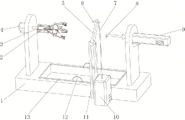
FIG. 1 is a schematic structural diagram of an overall efficient machining device for a seat valve body according to the present invention;
FIG. 2 is a schematic structural view of a collecting box of the efficient machining device for the valve body of the seat valve, which is provided by the invention, being detached from a machining table;
FIG. 3 is a schematic structural diagram of a clamping mechanism of an efficient machining device for a valve body of a seat valve according to the present invention;
FIG. 4 is a schematic structural diagram of a clamping mechanism of the efficient machining device for the valve body of the seat valve according to the present invention;
FIG. 5 is a schematic cross-sectional structural view of a clamping mechanism of an efficient machining device for a valve body of a seat valve according to the present invention;
fig. 6 is an enlarged view of a portion a in fig. 5.
Fig. 7 is a cross-sectional view of another improved embodiment of a clamping mechanism of a high-efficiency machining device for a valve body of a seat valve.
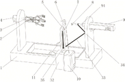
Fig. 8 is a schematic view of a first operating state of the modified embodiment of fig. 7.
Fig. 9 is a second operational state illustration of the modified embodiment of fig. 7.
In the figure: 1, a processing table, 2, a clamping motor, 3, a first mounting seat, 4, a rotating motor, 5, a rotating arm, 6, a spray nozzle, 7, an air pipe, 8, a milling cutter assembly, 9 electric telescopic cylinders, 91, telescopic rods, 10 air pressure generating devices, 11 support frames, 12 handles, 13 collecting boxes, 14 positioning pins, 15 threaded rods, 16 adjusting discs, 17 positioning columns and 18; the device comprises a connecting rod, a 19 mounting frame, a 20 rotating cylinder, a 21 clamping rod, a 22 clamping plate, a 23 sleeve, a 24 connecting shaft, a 25 guide support, a 26 through hole, a 27 connecting frame, a 28 first hollow rubber column, a 29 clamping head, a 30 second hollow rubber column and a 31 annular seat.
Detailed Description
The technical solution of the present patent will be described in further detail with reference to the following embodiments.
Example 1:
a high-efficiency processing device of a seat valve body is disclosed, as shown in figures 1-6, and comprises a processing table 1 and a clamping mechanism, wherein a rotating motor 4 is fixed on the outer wall of one side of the top of the processing table 1 through screws, the output end of the rotating motor 4 is rotatably connected with a first mounting seat 3, the clamping mechanism comprises a clamping motor 2 and an adjusting disc 16, the clamping motor 2 is fixed on the outer wall of one side of the first mounting seat 3 through screws, the output end of the clamping motor 2 is rotatably connected with a threaded rod 15, the adjusting disc 16 is connected with the outer wall of the threaded rod 15 through threads, a mounting frame 19 is mounted on the outer wall of one side of the first mounting seat 3 through a connecting rod 18, the mounting frame 19 is of a hexagonal structure, the outer wall of the mounting frame 19 is rotatably connected with six rotating cylinders 20, clamping rods 21 are welded on the outer wall of one side of the rotating cylinder 20, six through holes 26 for the clamping rods 21 to pass through are formed in the outer wall of one side of the adjusting disc 16, sleeves 23 are rotatably connected with the inner walls of two sides of the through connecting shaft 24, the six sleeves 23 are respectively sleeved on the outer walls of the six clamping rods 21, one end of each clamping rod 21 is integrally provided with a clamping plate 22, and the outer wall of one side of each clamping plate 22 is rotatably connected with a clamping head 29; an electric telescopic cylinder 9 is fixed on the outer wall of one side of the top of the processing table 1 through screws, and a milling cutter assembly 8 is arranged at the output end of the electric telescopic cylinder 9; through the arrangement of the clamping motor 2, the clamping rod 21, the adjusting disc 16 and other structures, the clamping motor 2 can be utilized to work to drive the threaded rod 15 to rotate, the sleeve 23 is sleeved outside the clamping rod 21, the threaded rod 15 rotates to drive the adjusting disc 16 to translate, so that the sleeve 23 slides on the clamping rod 21, along with the movement of the sleeve 23, the included angle between the clamping rod 21 and the threaded rod 15 is changed, the clamping head 29 is further promoted to gather inwards to clamp one end of the valve body, the rotating motor 4 works to drive the valve body to rotate through the clamping mechanism, the electric telescopic cylinder 9 sends the milling cutter assembly 8 out at a constant speed, the inner wall of the other end of the valve body is milled, and therefore the machining of threads is completed; the mode is good in fixing effect, the rotating center of the valve body can be kept consistent during each processing without complex positioning operation, and the mode can adapt to the valve bodies with different sizes.
In order to improve the stability; as shown in fig. 4 and 5, connecting frames 27 are welded on the outer walls of the two sides of the mounting frame 19, guide brackets 25 are welded on the outer walls of the two sides of the adjusting disc 16, and the adjusting disc 16 is slidably connected to the outer walls of the connecting frames 27 through the guide brackets 25; through setting up link 27 and guide bracket 25, can lead the displacement of adjusting disk 16, promote stability and reliability.
In order to improve the clamping firmness; as shown in fig. 6, the first hollow glue columns 28 are embedded and uniformly distributed on the outer wall of one side of the clamping head 29; through setting up first hollow glue post 28, can be when the centre gripping, utilize first hollow glue post 28 deformation to promote and the valve body between frictional force to promote the firmness.
The valve body is convenient to position; as shown in fig. 3, a positioning column 17 is fixed on the outer wall of one side of the connecting frame 27 through a screw, and the axis of the positioning column 17 is overlapped with the axis of the threaded rod 15; through setting up reference column 17, can be convenient for carry out assistance-localization real-time with valve body pot head in the reference column 17 outside, control fixture again and carry out the centre gripping, convenient operation has promoted the convenience.
In order to improve the positioning firmness; as shown in fig. 3 and 6, one end of the positioning column 17 is of a circular truncated cone structure, and second hollow rubber columns 30 which are uniformly distributed are embedded in the outer wall of the circumference of one end of the positioning column 17; through setting up second hollow gluey post 30, further promoted the location firmness.
In order to improve reliability; as shown in fig. 6, an annular seat 31 is fixed on the inner circumferential wall of the positioning post 17 through screws, and one end of the threaded rod 15 is rotatably connected to the inner wall of the annular seat 31.
This embodiment is when using, the valve body one end cover that will treat processing carries out assistance-localization real-time in the reference column 17 outside, the tight motor 2 work of control clamp again, drive threaded rod 15 and rotate, because sleeve 23 cup joints in supporting rod 21 outsidely, threaded rod 15 rotates and drives adjusting disk 16 translation, thereby make sleeve 23 slide on supporting rod 21, along with sleeve 23's removal, supporting rod 21 changes with threaded rod 15's contained angle, and then make holding head 29 gather together to the inboard, thereby carry out the centre gripping to valve body one end, it drives the valve body rotation through fixture to rotate 4 works of motor, electronic telescoping cylinder 9 sends out milling cutter assembly 8 at the uniform velocity, mill valve body other end inner wall, thereby accomplish threaded processing.
Example 2:
a high-efficiency processing device for a valve body of a seat valve is disclosed, which is shown in figure 1 and is used for cleaning chips after milling; the present embodiment is modified from embodiment 1 as follows: a support frame 11 is fixed on the outer wall of one side of the processing table 1 through screws, the top of the support frame 11 is rotatably connected with a rotating arm 5, a spray head 6 is clamped on the inner wall of one end of the rotating arm 5, an air pressure generating device 10 is arranged on one side of the processing table 1, and the spray head 6 is connected to the output end of the air pressure generating device 10 through an air pipe 7; through setting up rotor arm 5, shower nozzle 6 isotructure, can be after processing finishes, through rotating rotor arm 5, make shower nozzle 6 aim at the valve body, the work of control air pressure generating device 10 utilizes shower nozzle 6 to blow off the piece in the valve body, has promoted the practicality.
In order to collect the collected debris, as shown in fig. 1, a collecting box 13 is detachably mounted on the outer wall of the top of the processing table 1; through setting up collecting box 13, can be convenient for collect the piece that falls, promoted the practicality.
In order to further improve the practicability, as shown in fig. 1 and 2, two handles 12 are integrally arranged on the outer wall of the top of the collecting box 13, a positioning pin 14 is fixed on the outer wall of the bottom of the processing table 1 through a screw, and a pin hole matched with the positioning pin 14 is formed in the processing table 1; through setting up locating pin 14, can be convenient for carry out reliable location to collecting box 13, do benefit to the installation of collecting box 13, set up handle 12, be convenient for take out collecting box 13, promoted the practicality.
As another modified example: referring to fig. 7-9, the supporting frame 11 is longitudinally slidably disposed on a positioning seat 32, a right side region of the supporting frame 11 partially protrudes from the positioning seat 32, a spring for driving the supporting frame to move upwards is disposed in a sliding groove of the positioning seat, and a protruding triggering portion 38 is disposed on the right side of the supporting frame 11. The telescopic rod 91 of the electric telescopic cylinder 9 is provided with the pull rope 33 in a fixed sleeve mode, the pull rope 33 is guided through the first guide wheel 34 and the second guide wheel 35 (the first guide wheel 34 can be installed on a supporting seat below the electric telescopic cylinder 9, and the second guide wheel 35 can be installed on the supporting seat 11 or the positioning seat 32) to be connected to the rotating arm 5, so that when the telescopic rod 91 moves towards the direction of the first installation seat 3, the supporting seat 11 is pulled downwards by the pull rope, the supporting seat 32 slides downwards to form abdicating (refer to fig. 9), the milling cutter assembly 8 can normally process a workpiece, the triggering portion 38 also follows the supporting seat 11 downwards to be not in contact with the switch 37 on the air pressure generating device 10, when the spray head 6 forms abdicating, the air pressure generating device 10 does not work, and energy consumption is reduced. When the milling cutter assembly 8 finishes processing and retracting the workpiece, the pull rope 33 is loosened, no force is applied to the support frame 11, the support frame 11 moves upwards under the action of the spring 36, so that the spray head 6 and the workpiece are at the same horizontal height (refer to fig. 8), and in the moving process, the trigger part 38 presses the switch 37, so that the air pressure generating device 10 works. Through foretell process, realized that telescopic link and shower nozzle whether work link, automated control need not the manual work and operates atmospheric pressure generating device 10, raises the efficiency.
The above description is only for the purpose of illustrating the preferred embodiments of the present invention and is not intended to limit the scope of the present invention, which is defined by the claims and their equivalents, and all changes which come within the meaning and range of equivalency of the art are therefore intended to be embraced therein.