CN113367509B - Multifunctional table - Google Patents
Multifunctional table Download PDFInfo
- Publication number
- CN113367509B CN113367509B CN202110668008.5A CN202110668008A CN113367509B CN 113367509 B CN113367509 B CN 113367509B CN 202110668008 A CN202110668008 A CN 202110668008A CN 113367509 B CN113367509 B CN 113367509B
- Authority
- CN
- China
- Prior art keywords
- rod
- supporting
- flexible
- connecting strip
- vertical
- Prior art date
- Legal status (The legal status is an assumption and is not a legal conclusion. Google has not performed a legal analysis and makes no representation as to the accuracy of the status listed.)
- Active
Links
- 230000000694 effects Effects 0.000 claims abstract description 11
- 230000003014 reinforcing effect Effects 0.000 description 13
- 239000002184 metal Substances 0.000 description 5
- 238000004519 manufacturing process Methods 0.000 description 3
- 239000002023 wood Substances 0.000 description 3
- 238000010586 diagram Methods 0.000 description 2
- 238000004026 adhesive bonding Methods 0.000 description 1
- 238000005452 bending Methods 0.000 description 1
- 230000009286 beneficial effect Effects 0.000 description 1
- 238000005516 engineering process Methods 0.000 description 1
- 238000010030 laminating Methods 0.000 description 1
- 239000000463 material Substances 0.000 description 1
- 238000000034 method Methods 0.000 description 1
- 230000000149 penetrating effect Effects 0.000 description 1
- 230000002787 reinforcement Effects 0.000 description 1
- 238000007790 scraping Methods 0.000 description 1
Images




Classifications
-
- A—HUMAN NECESSITIES
- A47—FURNITURE; DOMESTIC ARTICLES OR APPLIANCES; COFFEE MILLS; SPICE MILLS; SUCTION CLEANERS IN GENERAL
- A47B—TABLES; DESKS; OFFICE FURNITURE; CABINETS; DRAWERS; GENERAL DETAILS OF FURNITURE
- A47B87/00—Sectional furniture, i.e. combinations of complete furniture units, e.g. assemblies of furniture units of the same kind such as linkable cabinets, tables, racks or shelf units
- A47B87/002—Combination of tables; Linking or assembling means therefor
-
- A—HUMAN NECESSITIES
- A47—FURNITURE; DOMESTIC ARTICLES OR APPLIANCES; COFFEE MILLS; SPICE MILLS; SUCTION CLEANERS IN GENERAL
- A47B—TABLES; DESKS; OFFICE FURNITURE; CABINETS; DRAWERS; GENERAL DETAILS OF FURNITURE
- A47B13/00—Details of tables or desks
- A47B13/02—Underframes
-
- A—HUMAN NECESSITIES
- A47—FURNITURE; DOMESTIC ARTICLES OR APPLIANCES; COFFEE MILLS; SPICE MILLS; SUCTION CLEANERS IN GENERAL
- A47B—TABLES; DESKS; OFFICE FURNITURE; CABINETS; DRAWERS; GENERAL DETAILS OF FURNITURE
- A47B13/00—Details of tables or desks
- A47B13/08—Table tops; Rims therefor
-
- A—HUMAN NECESSITIES
- A47—FURNITURE; DOMESTIC ARTICLES OR APPLIANCES; COFFEE MILLS; SPICE MILLS; SUCTION CLEANERS IN GENERAL
- A47B—TABLES; DESKS; OFFICE FURNITURE; CABINETS; DRAWERS; GENERAL DETAILS OF FURNITURE
- A47B13/00—Details of tables or desks
- A47B13/08—Table tops; Rims therefor
- A47B13/10—Tops characterised by shape, other than circular or rectangular
-
- F—MECHANICAL ENGINEERING; LIGHTING; HEATING; WEAPONS; BLASTING
- F16—ENGINEERING ELEMENTS AND UNITS; GENERAL MEASURES FOR PRODUCING AND MAINTAINING EFFECTIVE FUNCTIONING OF MACHINES OR INSTALLATIONS; THERMAL INSULATION IN GENERAL
- F16B—DEVICES FOR FASTENING OR SECURING CONSTRUCTIONAL ELEMENTS OR MACHINE PARTS TOGETHER, e.g. NAILS, BOLTS, CIRCLIPS, CLAMPS, CLIPS OR WEDGES; JOINTS OR JOINTING
- F16B7/00—Connections of rods or tubes, e.g. of non-circular section, mutually, including resilient connections
- F16B7/18—Connections of rods or tubes, e.g. of non-circular section, mutually, including resilient connections using screw-thread elements
Landscapes
- Engineering & Computer Science (AREA)
- General Engineering & Computer Science (AREA)
- Mechanical Engineering (AREA)
- Accommodation For Nursing Or Treatment Tables (AREA)
- Tables And Desks Characterized By Structural Shape (AREA)
Abstract
The utility model relates to a multifunctional table relates to the field of furniture, and it includes the table body and middle seat, and the table body is provided with two, and the middle seat sets up between two table bodies, and the both ends of middle seat are connected with the one end that two table bodies set up in opposite directions respectively, and the middle seat is used for making when the angle between two table bodies changes, makes between the two table bodies still can remain stable connection. The application has the effect of being suitable for different use environments.
Description
Technical Field
The application relates to the field of furniture, in particular to a multifunctional table.
Background
The table is a common furniture, and is provided with a table board on the upper part and a supporting seat on the lower part. The table can be used for placing things or doing things on the table for eating, writing, working or playing cards, and is mainly divided into two types according to materials, wherein the first type is a pure wood table with a table plate and a supporting seat both made of wood, and the second type is a combined table with a table plate made of wood and a supporting seat supported by a metal pipe.
In the related art, three types of tables are commonly used in restaurants to meet different use requirements, a long table is arranged at a position close to a wall for multiple guests to use simultaneously, a short table is arranged at a position with a smaller space for single or fewer guests to use, and an L-shaped table (namely, a table in an L shape in a overlooking manner) is arranged at a corner position.
In view of the above-mentioned related technologies, the inventor believes that three kinds of tables are arranged in a restaurant as required, each table needs to be separately designed and produced, which results in an increase in the cost of the corollary production, and thus needs to be improved.
Disclosure of Invention
In order to solve the problem that the production cost of table matching with various specifications is too high, the multifunctional table is provided.
The multifunctional table provided by the application adopts the following technical scheme.
A multi-function table, comprising:
the table comprises two table bodies, wherein each table body comprises a supporting seat and a table plate;
the middle seat comprises a flexible inner connecting strip, a flexible outer connecting strip and supporting rods, two ends of the flexible inner connecting strip and two ends of the flexible inner connecting strip are respectively in telescopic connection with two long edge sides of the two table plates, the supporting rods are provided with a plurality of pieces, and two ends of each supporting rod are respectively in sliding connection with the flexible inner connecting strip and the flexible outer connecting strip;
when the two table plates are arranged side by side along the length direction, the flexible inner connecting strips and the flexible outer connecting strips are parallel to each other, and the supporting rods are tightly attached to each other; when the length directions of the two table plates are crossed, the flexible inner connecting strips and the flexible outer connecting strips are bent to be arranged in an arc shape, and the supporting rods are swung open in a fan shape.
By adopting the technical scheme, when the multifunctional table is used as a long table to be close to a wall as required, only two table bodies are required to be arranged side by side along the length direction of the table body, and all the supporting rods can be tightly closed together, so that all the supporting rods can form a rectangular plate shape, and redundant parts of the flexible inner connecting strips and the flexible outer connecting strips are retracted into the table plate, so that the two table bodies and the supporting seat can form the rectangular long table; when the multifunctional table is required to be used as a corner table or a table with other angles, the two table bodies are placed at a specified angle, then the supporting rods are unfolded in a fan shape, and the parts, between the two table bodies, of the flexible inner connecting strips and the flexible outer connecting strips are bent to enable the two ends of the supporting rods to be supported respectively, so that the whole middle seat is arranged in a fan shape, and at the moment, the two table bodies respectively connected with the two ends of the middle seat can be stably connected at the specified angle; when needs use this desk as short table, only need with two table bodies side by side along the width direction of the table body, and make each bracing piece can be the semicircle form and expand, flexible inner connecting strip and flexible outer connecting strip be in two partial bending between the table body so that can prop the both ends of each bracing piece respectively can, thereby make the whole semicircle shape setting that is of midseat, at this moment, two table bodies can be stable link together side by side, and the midseat can play the effect that expands the usage space a little.
Optionally, the flexible inner connecting strip and the flexible outer connecting strip both include:
the attaching part is matched with the side edge of the table plate;
the movable part is arranged on one side surface, which is attached to the table board, of the attaching part;
the two long side edges of the two table plates are respectively provided with a first sliding clamping groove, and the movable parts are respectively clamped in the corresponding first sliding clamping grooves in a sliding manner.
Through adopting above-mentioned technical scheme, utilize laminating portion to ensure the area of contact between flexible interior connecting strip and the flexible outer connecting strip and the table, utilize cooperation between movable part and the first draw-in groove that slides to realize the scalable connection between flexible interior connecting strip and the flexible outer connecting strip and the table, when needs accomodate into the table with the unnecessary part of flexible interior connecting strip and flexible outer connecting strip in, only need with flexible interior connecting strip and the flexible outer connecting strip need accomodate the part towards the table body keep away from the one end pull of midseat can.
Optionally, the support rod includes:
the support rod comprises a support rod, a plurality of abdicating grooves and a plurality of fixing grooves, wherein the abdicating grooves are arranged in a plurality of ways, each abdicating groove is uniformly distributed on the end surfaces of two ends of the support rod, and each abdicating groove arranged on the same end of the support rod is arranged along the height direction of the support rod;
when the end part of the supporting rod is connected with the flexible inner connecting strip or the flexible outer connecting strip, the abdicating grooves are respectively connected with the movable parts in a sliding and clamping manner.
Through adopting above-mentioned technical scheme, utilize the cooperation between the groove of stepping down and the movable part for the bracing piece can be connected with flexible outer connecting strip (or flexible interior connecting strip) are stable.
Optionally, the flexible inner connecting strip and the flexible outer connecting strip both include:
the two ends of the flexible connecting strip are provided with through holes;
the locking piece is provided with two locking pieces which are respectively arranged at two ends of the flexible connecting strip, the locking piece comprises a fastening bolt and a nut, and a bolt body of the fastening bolt penetrates through the through hole and is in threaded connection with the nut;
wherein, be provided with the second draw-in groove that slides that extends along table length direction on the side of table, fastening bolt's nut slides the draw-in groove joint with the second.
Through adopting above-mentioned technical scheme, partly reverse plug-in connection slides in order to realize the joint that slides between the two in the draw-in groove through the nut with fastening bolt, then wear to establish the perforation with fastening bolt's the key body, and wear to establish the effect that the nut can reach the tight flexible connection strip of clamp at the fastening bolt key body, thereby make and to keep fixed between flexible connection strip and the table, can also adjust the position according to actual need simultaneously, realize the stable connection between flexible outer joint strip and the flexible inner joint strip and the table.
Optionally, the flexible connecting strip is further provided with:
the adjusting groove extends along the length direction of the flexible connecting strip;
the adjusting bolts are provided with a plurality of adjusting bolts, the bolt body of each adjusting bolt penetrates through the adjusting groove and is in threaded connection with the end part of the supporting rod, and the adjusting bolts are matched with the supporting rod to achieve the effect of clamping the flexible connecting strip.
Through adopting above-mentioned technical scheme, utilize the adjustment tank that sets up on flexible connection strip for adjusting bolt of pegging graft on the adjustment tank can reach the effect of fixed connection flexible connection strip and bracing piece through with bracing piece tip threaded connection, simultaneously, makes the bracing piece can be according to actual demand adjustment position, and the middle table of being convenient for changes the shape.
Optionally, the middle seat further includes:
the supporting frames are provided with two supporting frames, one ends of the two supporting frames, which are arranged oppositely, are respectively and rotatably connected with one ends of the two supporting seats, which are arranged oppositely, and the upper surfaces of the two supporting frames and the lower surfaces of the supporting rods are positioned on the same horizontal plane;
the support frame is rotatably connected with the support seat at a position close to the flexible outer connecting strip, and a rotating shaft between the support frame and the support seat is vertically arranged.
Through adopting above-mentioned technical scheme, utilize the cooperation between support frame and the supporting seat for when needing to keep appointed angle between two table bodies, can carry out the reinforcement through the support frame and support each bracing piece, avoid taking place after the supporting seat surface pressurized sunken.
Optionally, the support frame includes:
the upright post is vertically arranged and is rotationally connected with the supporting seat;
one end of the horizontal rod is fixed with the upper end of the vertical rod, and the upper surface of the horizontal rod and the lower surfaces of the supporting rods are in the same horizontal plane;
the upper end of the diagonal brace is connected with one end of the horizontal rod, which is far away from the vertical rod, and the lower end of the diagonal brace is connected with the lower end of the vertical rod;
wherein, the pole setting is located the vertical projection plane of table.
Through adopting above-mentioned technical scheme, utilize the pole setting to realize the rotation relation of being connected between support frame and the supporting seat, utilize the horizon bar to play the effect of each corresponding bracing piece in support position, utilize the diagonal brace to play the one end of propping the unsettled setting of horizon bar for the use of horizon bar is safer, stable.
Optionally, the supporting seat includes:
the upper supporting frame is horizontally arranged and fixed with the lower surface of the table board;
the vertical supporting frame is vertically arranged and is parallel to the short side of the table plate, and the upper end of the vertical supporting frame is fixedly connected with one end, far away from the supporting frame, of the upper supporting frame;
the lower connecting rod extends along the length direction of the table and is located below one side of the table, which is provided with the flexible outer connecting strip, one end of the lower connecting rod is connected with the lower end of the vertical supporting frame, and the other end of the lower connecting rod is connected with the lower end of the supporting frame in a rotating mode.
Through adopting above-mentioned technical scheme, utilize the carriage to play the effect of outrigger table, utilize the cooperation between carriage, lower connecting rod and the support frame to play the effect of outrigger on the outrigger to make the table can the stable use.
Optionally, the method further includes:
the movable connecting rod assembly comprises two first connecting rods and two second connecting rods, one ends of the two first connecting rods, which are opposite to each other, are rotatably connected with the two supporting frames respectively, and two ends of the second connecting rods are slidably and rotatably connected with the two first connecting rods respectively.
Through adopting above-mentioned technical scheme, the movable connecting rod subassembly that the utilization is constituteed has the head rod and second connecting rod can be in the same place the stable connection of the lower extreme of two support frames for also can stable connection between the lower extreme of two table bodies.
In summary, the present application includes at least one of the following beneficial technical effects:
the table can be converted into various forms according to actual needs, meets different use requirements, and is wider in application range;
the structure is simple, the production and the implementation are convenient, and the desk can be transformed and used on the existing desk, so that the popularization is convenient;
the use is more convenient, and the user can not have too much restriction on the legs when sitting down for use, especially when the table is used as a corner table.
Drawings
Fig. 1 is a front view of a multifunctional table according to a first embodiment of the present application;
fig. 2 is a front view of a table body according to a first embodiment of the application;
FIG. 3 is a front view of the support base according to the first embodiment of the present application;
FIG. 4 is a front view of the center seat according to the first embodiment of the present application;
FIG. 5 is a schematic view of the use of the flexible inner connecting strip and the flexible outer connecting strip of the first embodiment of the present application;
fig. 6 is a schematic view of a mounting bar according to a first embodiment of the present application;
FIG. 7 is a schematic structural diagram of a supporting rod according to a first embodiment of the present application;
FIG. 8 is a schematic structural diagram of a supporting frame according to a first embodiment of the present application;
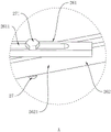
FIG. 9 is an enlarged partial schematic view of A of FIG. 8;
FIG. 10 is a schematic view of the use of the flexible inner connecting strip and the flexible outer connecting strip of example two of the present application;
fig. 11 is a schematic view of a mounting bar according to a second embodiment of the present application;
FIG. 12 is a schematic view of the support rod of the second embodiment of the present application; .
Reference numerals: 1. a table body; 11. a supporting seat; 111. an upper support frame; 112. erecting a support frame; 1121. a bottom bar; 1122. a vertical rod; 1123. a diagonal bar; 113. a lower connecting rod; 12. a table plate; 2. a middle seat; 21. a flexible inner connecting strip; 211. a bonding section; 2111. a metal plate; 212. a movable portion; 2121. an outer supporting plate; 2122. an arc-shaped plate; 213. a flexible connecting strip; 2131. perforating; 2132. an adjustment groove; 214. a locking member; 2141. fastening a bolt; 2142. a nut; 215. adjusting the bolt; 22. a flexible outer connecting strip; 23. a support bar; 231. a yielding groove; 232. a limiting part; 24. a support frame; 241. erecting a rod; 242. a horizontal bar; 243. a diagonal brace; 25. mounting a bar; 251. a slot; 252. a limiting chute; 253. a first sliding clamping groove; 254. a second sliding clamping groove; 26. a movable link assembly; 261. a first connecting rod; 2611. a first sliding groove; 262. a second connecting rod; 2621. a second sliding groove; 27. sliding the column; 271. a limiting block; 28. a first reinforcing bar; 281. a second reinforcing bar.
Detailed Description
The present application is described in further detail below with reference to figures 1-12.
The embodiment of the application discloses a multifunctional table.
Example 1:
referring to fig. 1, the multifunctional table comprises a table body 1 and a middle seat 2, wherein the table body 1 is provided with two parts, the middle seat 2 is arranged between the two table bodies 1, two ends of the middle seat 2 are respectively connected with one ends of the two table bodies 1 which are arranged oppositely, and the middle seat 2 is used for enabling the two table bodies 1 to be stably connected when an angle between the two table bodies 1 changes.
Referring to fig. 1 and 2, each of the two table bodies 1 includes a support 11 and a table 12, each support 11 includes an upper support frame 111, a vertical support frame 112 and a lower connecting rod 113, the upper support frame 111 is horizontally disposed on the lower surface of the table 12, the vertical support frame 112 is vertically disposed on one end of the upper support frame 111 away from the middle seat 2, a plane where the vertical support frame 112 is disposed is parallel to a short side of the table 12, the lower connecting rod 113 is horizontally disposed under one long side of the table 12, and two ends of the lower connecting rod 113 are respectively connected to a lower end of the vertical support frame 112 and a lower end of the middle seat 2; wherein, all be provided with the rubber lower margin at founding braced frame 112 bottom both ends, utilize the rubber lower margin can avoid taking place the scraping with ground when the table body 1 removes.
Referring to fig. 3, the vertical support frame 112 includes a bottom rod 1121, a vertical rod 1122 and an inclined rod 1123, the bottom rod 1121 is horizontally disposed below the upper support frame 111, the vertical rod 1122 is vertically disposed, and upper and lower ends of the vertical rod 1122 are respectively connected to the bottom rod 1121 and the upper support frame 111, the lower end of the vertical rod 1122 is located at the end of the bottom rod 1121, the lower end of the inclined rod 1123 is connected to one end of the bottom rod 1121, which is far away from the vertical rod 1122, and the upper end of the inclined rod 1123 is obliquely disposed toward the direction close to the vertical rod 1122 and is connected to the upper support frame 111.
Referring to fig. 4, the middle seat 2 includes a flexible inner connecting bar 21, a flexible outer connecting bar 22, supporting bars 23 and supporting frames 24, two ends of the flexible inner connecting bar 21 are respectively connected with two table plates 12 in a telescopic manner near a long side of the vertical bar 1122, two ends of the flexible outer connecting bar 22 are respectively connected with two table plates 12 in a telescopic manner near a long side of the diagonal bar 1123, the supporting bars 23 are provided with a plurality of supporting bars, two ends of each supporting bar 23 are respectively connected with the flexible inner connecting bar 21 and the flexible outer connecting bar 22 in a sliding manner, the supporting frames 24 are provided with two supporting frames, the two supporting frames 24 are respectively connected with one side of the two bases in a rotating manner, and the two supporting frames 24 are used for supporting the corresponding supporting bars 23.
Referring to fig. 4 and 5, the middle seat 2 further includes a plurality of four mounting bars 25, each mounting bar 25 is respectively disposed on two long sides of the two tables 12, and the end portions of the flexible inner connecting bars 21 (or the flexible outer connecting bars 22) are movably inserted into the mounting bars 25 to realize the telescopic connection between the flexible inner connecting bars 21 (or the flexible outer connecting bars 22) and the tables 12.
Referring to fig. 4 and 7, the mounting bar 25 is fixedly mounted on the side surface of the table 12 by means of bolt locking or gluing, a slot 251 extending along the length direction of the mounting bar 25 for inserting the flexible inner connecting bar 21 (or the flexible outer connecting bar 22) is arranged in the mounting bar 25, a limiting sliding slot 252 extending along the length direction of the mounting bar 25 is arranged on one side of the mounting bar 25 away from the table 12, one side of the limiting sliding slot 252 close to the table 12 is communicated with one side of the slot 251 away from the table 12, the width of the limiting sliding slot 252 is smaller than that of the slot 251, and a plurality of first sliding slots 253 arranged in an up-and-down position relationship are also arranged in the mounting bar 25; the flexible inner connecting strip 21 (or the flexible outer connecting strip 22) includes a fitting portion 211 and a moving portion 212, the fitting portion 211 is inserted into the slot 251, the moving portion 212 is provided with a plurality of channels, and each moving portion 212 is inserted into each first sliding slot 253.
Referring to fig. 6, the attaching portion 211 includes a plurality of metal plates 2111 arranged along the thickness direction of the table 12, each moving portion 212 is disposed between any two adjacent metal plates 2111, each moving portion 212 includes an outer supporting plate 2121 and an arc plate 2122, the outer supporting plate 2121 is provided with two pieces, the distance between the sides of the two outer supporting plates 2121 far away from the table 12 is smaller than the distance between the sides of the two supporting rods 23 near the table 12, the side of the two outer supporting plates 2121 far away from the table 12 is connected to a long side of the two adjacent metal plates 2111, the sides of the two outer supporting plates 2121 near the table 12 are connected to two long sides of the arc plate 2122, and the inner concave surface of the arc plate 2122 faces the direction far away from the table 12; when the flexible inner connecting bar 21 (or the flexible outer connecting bar 22) is connected to the mounting bar 25, the outer wall of the movable portion 212 is closely attached to the inner wall of the first sliding groove 253.
Referring to fig. 8, two end faces of each support rod 23 are provided with two yielding grooves 231, and when the end of each support rod 23 is connected to the flexible inner connecting strip 21 (or the flexible outer connecting strip 22), each movable portion 212 is embedded in the two yielding grooves 231, so as to realize the sliding and clamping between the end of each support rod 23 and the flexible inner connecting strip 21 and the flexible outer connecting strip 22.
Referring to fig. 8, the supporting frame 24 includes an upright post 241, a horizontal rod 242 and an inclined strut 243, the upright post 241 is vertically disposed, and upper and lower ends of the upright post 241 are rotatably connected to the upper supporting frame 111 and the lower connecting rod 113, respectively, an upper end surface of the upright post 241 is attached to a lower surface of the upper supporting frame 111, the horizontal rod 242 is horizontally disposed, and one end of the horizontal rod 242 is fixed to an upper end of the upright post 241, an upper surface of the horizontal rod 242 and a lower surface of each supporting rod 23 are located on the same horizontal plane, and upper and lower ends of the inclined strut 243 are fixed to the horizontal rod 242 and the upright post 241, respectively; the upper end of the inclined strut 243 is fixed to one end of the horizontal rod 242 away from the vertical rod 241, and the lower end of the inclined strut 243 is fixed to the lower end of the vertical rod 241 and near the middle.
The user can be through rotating support frame 24 with the position of adjustment horizon bar 242 to make support frame 24 can prop many spinal branchs vaulting pole 23, avoid taking place the slope after bracing piece 23 pressurized, ensure the safe in utilization on middle seat 2 surface.
Referring to fig. 8 and 9, the middle base 2 further includes a movable connecting rod assembly 26 disposed between the two supporting frames 24, the movable connecting rod assembly 26 includes a first connecting rod 261 and a second connecting rod 262, two ends of the first connecting rod 261, which are disposed oppositely, are rotatably connected to lower ends of the two upright rods 241, respectively, and two ends of the second connecting rod 262 are slidably and rotatably connected to ends of the two first connecting rods 261, which are disposed oppositely; wherein each first connecting rod 261 is provided with a first sliding groove 2611 extending along the length direction of the first connecting rod 261, both ends of the second connecting rod 262 are provided with second sliding grooves 2621 extending along the length direction of the second connecting rod 262, the parts of the two first sliding grooves 2611 which are staggered with the two first sliding grooves 2611 are provided with sliding columns 27, the upper and lower ends of the sliding columns 27 are respectively penetrated out of the first sliding grooves 2611 and the second sliding grooves 2621, and the upper and lower surfaces of the sliding column 27 are provided with stoppers 271 respectively abutted against the upper surface of the first connecting rod 261 and the lower surface of the second connecting rod 262, through the cooperation between the sliding column 27 and the first sliding slot 2611, the second connecting rod 262 can be connected with the first connecting rod 261 in a sliding manner, meanwhile, the second connecting rod 262 can rotate relative to the first connecting rod 261 to adjust the angle therebetween.
Referring to fig. 8, the second connecting rod 262 is disposed below the first connecting rod 261, a vertically disposed first reinforcing rod 28 is disposed in the middle of the first connecting rod 261, a second reinforcing rod 281 horizontally disposed and attached to the lower surface of each support rod 23 is disposed at the upper end of the first reinforcing rod 28, and the lower end of the first reinforcing rod 28 is disposed to contact the ground.
The implementation principle of the embodiment 1 is as follows:
when two table bodies 1 need to be arranged side by side along the length direction to form a long table which can lean against a wall body for use in a combined manner, at first, each support rod 23 is tightly folded together, at the moment, redundant parts of the flexible inner connecting strip 21 and the flexible outer connecting strip 22 are stored in the mounting strip 25, one ends of two support frames 24 far away from the vertical rod 241 are rotated towards the opposite direction, meanwhile, the second connecting rod 262 needs to be pushed towards the direction far away from the wall body, so that the two ends of the second reinforcing rod 281 can respectively support the corner parts of two table plates 12, and meanwhile, the second reinforcing rod 281 can be used for supporting each support.
When the two table bodies 1 are required to form a corner table, the positions of the two table bodies 1 are firstly adjusted to enable the length directions of the two table bodies 1 to be crossed, the length and shape of the flexible inner connecting strips 21 and the flexible outer connecting strips 22 between the two table bodies 1 are then adjusted, and at this time, the length of the flexible outer connecting strip 22 between the two table bodies 1 is longer than the length of the flexible inner connecting strip 21 between the two table bodies 1, and the position of each supporting rod 23 is adjusted, so that each supporting rod 23 can be unfolded in a fan shape, meanwhile, the positions of the two supporting frames 24 and the first reinforcing bar 28 need to be adjusted, so that the ends of the two supporting frames 24 far away from the vertical bar 241 rotate towards opposite directions, and the first reinforcing bar 28 is moved to a position close to the two vertical bars 241, and at this time, the second reinforcing bar 281 can abut on one end of the partial supporting bar 23 close to the flexible outer connecting bar 22.
When two table bodies 1 need to be arranged side by side along the width direction to form a short table, firstly, the two table bodies 1 are arranged along the width direction of the table body 1 and are parallel to each other, at the moment, the long sides of the two table bodies 1 close to the lower connecting rod 113 are arranged close to each other, at the moment, the length of the flexible outer connecting strip 22 between the two table bodies 1 is smaller than the length of the flexible inner connecting strip 21 between the two table bodies 1, then, one end of the two supporting frames 24 far away from the vertical rod 241 rotates towards the opposite direction, and the first reinforcing rod 28 is moved to the position far away from the vertical rod 241, so that the second reinforcing rod 281 can abut against one end of part of the supporting rod 23 far away from the flexible outer connecting strip 22.
Example 2:
referring to fig. 10, the present embodiment is different from embodiment 1 in that the flexible inner connecting bar 21 and the flexible outer connecting bar 22 each include a flexible connecting bar 213, a locking member 214, and an adjusting bolt 215, two ends of the flexible connecting bar 213 are respectively inserted into two corresponding mounting bars 25, the locking member 214 is used for fixing the flexible connecting bar 213 and the mounting bars 25, and the adjusting bolt 215 is used for fixedly connecting the end of the support rod 23 and the flexible connecting bar 213.
Referring to fig. 11, both ends of the flexible connecting bar 213 are provided with through holes 2131, the locking member 214 includes a fastening bolt 2141 and a nut 2142, the fastening bolt 2141 is inserted through the through holes 2131, and the nut 2142 is in threaded connection with the fastening bolt 2141 through the part of the bolt inserted through the through holes 2131; the mounting bar 25 is provided with a second sliding groove 254 with a T-shaped cross section instead of the first sliding grooves 253 described in embodiment 1, the nut of the fastening bolt 2141 is clamped in the second sliding groove 2621, and the bolt body of the fastening bolt 2141 extends out of the mounting bar 25.
Referring to fig. 12, the flexible connecting strip 213 is provided with a plurality of adjusting grooves 2132 extending in the length direction of the flexible connecting strip 213, the adjusting bolts 215 are provided with a plurality of adjusting bolts 215, the bolt body of each adjusting bolt 215 penetrates through the flexible connecting strip 213 through the adjusting grooves 2132, the part of each adjusting bolt 215 penetrating through the adjusting grooves 2132 is in threaded connection with the end part of the supporting rod 23, and the nut of each adjusting bolt 215 is attached to one side surface of the flexible connecting strip 213 away from the supporting rod 23; wherein, the bracing piece 23 not only can adjust the hookup location of bracing piece 23 tip and flexible connecting strip 213 through the cooperation between adjusting bolt 215 and the flexible connecting strip 213, can also fix the effect of bracing piece 23 simultaneously, ensures the stable expansion of bracing piece 23.
Wherein, the upper surface of each support rod 23 is provided with a limiting part which is attached to the upper surface of the flexible connecting strip.
The above embodiments are preferred embodiments of the present application, and the protection scope of the present application is not limited by the above embodiments, so: all equivalent changes made according to the structure, shape and principle of the present application shall be covered by the protection scope of the present application.
Claims (7)
1. A multi-function table, comprising:
the table comprises two table bodies (1), wherein each table body (1) comprises a supporting seat (11) and a table plate (12);
the table board comprises a table board body and a middle seat (2), wherein the middle seat (2) comprises a flexible inner connecting strip (21), a flexible outer connecting strip (22) and supporting rods (23), the two ends of the flexible inner connecting strip (21) and the two ends of the flexible inner connecting strip (21) are respectively in telescopic connection with the two long side sides of two table boards (12), the supporting rods (23) are provided with a plurality of pieces, and the two ends of each supporting rod (23) are respectively in sliding connection with the flexible inner connecting strip (21) and the flexible outer connecting strip (22);
when the two table plates (12) are arranged side by side along the length direction, the flexible inner connecting strip (21) and the flexible outer connecting strip (22) are parallel to each other, and the supporting rods (23) are tightly attached to each other; when the length directions of the two table plates (12) are crossed with each other, the flexible inner connecting strips (21) and the flexible outer connecting strips (22) are both bent to be arranged in an arc shape, and the supporting rods (23) are swung open in a fan shape;
wherein the flexible inner connecting strip (21) and the flexible outer connecting strip (22) both comprise:
the attaching part (211), the attaching part (211) is matched with the side edge of the desk plate (12);
a movable part (212), wherein the movable part (212) is arranged on one side surface of the joint part (211) jointed with the table board (12);
first sliding clamping grooves (253) are formed in two long side sides of the two table plates (12), and the movable parts (212) are respectively clamped in the corresponding first sliding clamping grooves (253) in a sliding mode;
wherein the support bar (23) comprises:
the abdicating groove (231) is provided with a plurality of abdicating grooves (231), each abdicating groove (231) is uniformly distributed on the end faces of the two ends of the supporting rod (23), and the abdicating grooves (231) arranged on the same end of the supporting rod (23) are arranged along the height direction of the supporting rod (23);
when the end part of the supporting rod (23) is connected with the flexible inner connecting strip (21) or the flexible outer connecting strip (22), each abdicating groove (231) is respectively clamped with each movable part (212) in a sliding way.
2. A multi-function table according to claim 1, wherein the flexible inner connecting strip (21) and the flexible outer connecting strip (22) each comprise:
the flexible connecting strip (213), both ends of the flexible connecting strip (213) are provided with through holes (2131);
the locking piece (214), the locking piece (214) is provided with two pieces, the two locking pieces (214) are respectively arranged on two ends of the flexible connecting bar (213), the locking piece (214) comprises a fastening bolt (2141) and a nut (2142), and a bolt body of the fastening bolt (2141) penetrates through the through hole (2131) and is in threaded connection with the nut (2142);
wherein, be provided with on the side of table (12) along second draw-in groove (254) that slides of table (12) length direction extension, the nut and the second draw-in groove (254) that slides of fastening bolt (2141) joint that slides.
3. A multi-purpose table according to claim 2, wherein said flexible connecting strips (213) are further provided with:
an adjustment groove (2132), the adjustment groove (2132) extending in the longitudinal direction of the flexible connecting strip (213);
the adjusting bolts (215), the adjusting bolts (215) are provided with a plurality of bolts, the bolt body of each adjusting bolt (215) penetrates through the adjusting groove (2132) and is in threaded connection with the end part of the supporting rod (23), and the adjusting bolts (215) are matched with the supporting rod (23) to achieve the effect of clamping the flexible connecting strip (213).
4. A multifunctional table according to claim 1, characterized in that said intermediate seat (2) further comprises:
the two supporting frames (24) are arranged on the supporting frame (24), one ends of the two supporting frames (24) which are oppositely arranged are respectively and rotatably connected with one ends of the two supporting seats (11) which are oppositely arranged, and the upper surfaces of the two supporting frames (24) and the lower surfaces of the supporting rods (23) are positioned on the same horizontal plane;
the supporting frame (24) is rotatably connected with the supporting seat (11) at a position close to the flexible outer connecting strip (22), and a rotating shaft between the supporting frame (24) and the supporting seat (11) is vertically arranged.
5. A multi-function table according to claim 4, wherein the support bracket (24) comprises:
the vertical rod (241), the vertical rod (241) is vertically arranged, and the vertical rod (241) is rotatably connected with the supporting seat (11);
one end of the horizontal rod (242) is fixed with the upper end of the vertical rod (241), and the upper surface of the horizontal rod (242) and the lower surface of each support rod (23) are in the same horizontal plane;
the upper end of the inclined strut (243) is connected with one end, away from the vertical rod (241), of the horizontal rod (242), and the lower end of the inclined strut (243) is connected with the lower end of the vertical rod (241);
wherein the vertical rod (241) is positioned in the vertical projection plane of the table plate (12).
6. A multi-function table according to claim 4, wherein said support (11) comprises:
the upper supporting frame (111) is horizontally arranged, and the upper supporting frame (111) is fixed with the lower surface of the table plate (12);
the vertical supporting frame (112) is vertically arranged, the vertical supporting frame (112) is parallel to the short side of the table plate (12), and the upper end of the vertical supporting frame (112) is fixedly connected with one end, far away from the supporting frame (24), of the upper supporting frame (111);
the table comprises a lower connecting rod (113), the lower connecting rod (113) extends along the length direction of the table (12) and is located below one side, provided with a flexible outer connecting strip (22), of the table (12), one end of the lower connecting rod (113) is connected with the lower end of the vertical supporting frame (112), and the other end of the lower connecting rod (113) is rotatably connected with the lower end of the supporting frame (24).
7. The multi-function table as claimed in claim 4, further comprising:
the movable connecting rod assembly (26) comprises a first connecting rod (261) and a second connecting rod (262), the first connecting rod (261) is provided with two ends, opposite to the first connecting rod (261), of the first connecting rod are respectively connected with the two supporting frames (24) in a rotating mode, and two ends of the second connecting rod (262) are respectively connected with the two first connecting rods (261) in a sliding mode and in a rotating mode.
Priority Applications (1)
| Application Number | Priority Date | Filing Date | Title |
|---|---|---|---|
| CN202110668008.5A CN113367509B (en) | 2021-06-16 | 2021-06-16 | Multifunctional table |
Applications Claiming Priority (1)
| Application Number | Priority Date | Filing Date | Title |
|---|---|---|---|
| CN202110668008.5A CN113367509B (en) | 2021-06-16 | 2021-06-16 | Multifunctional table |
Publications (2)
| Publication Number | Publication Date |
|---|---|
| CN113367509A CN113367509A (en) | 2021-09-10 |
| CN113367509B true CN113367509B (en) | 2022-08-12 |
Family
ID=77572821
Family Applications (1)
| Application Number | Title | Priority Date | Filing Date |
|---|---|---|---|
| CN202110668008.5A Active CN113367509B (en) | 2021-06-16 | 2021-06-16 | Multifunctional table |
Country Status (1)
| Country | Link |
|---|---|
| CN (1) | CN113367509B (en) |
Citations (8)
| Publication number | Priority date | Publication date | Assignee | Title |
|---|---|---|---|---|
| DE19825815C1 (en) * | 1998-06-09 | 2000-02-24 | Egon Heinzle | Stand for rod or plate-shaped objects |
| CN105231701A (en) * | 2015-10-19 | 2016-01-13 | 常州市武进亚太机电配件有限公司 | Bendable armrest |
| CN207084479U (en) * | 2017-03-10 | 2018-03-13 | 华南理工大学 | Flat plate folding table and composite furniture |
| CN207949368U (en) * | 2018-02-26 | 2018-10-12 | 丁元利 | A kind of portable multifunctional table and chair |
| CN109892824A (en) * | 2019-04-04 | 2019-06-18 | 杨双 | Desk |
| CN209518499U (en) * | 2018-07-09 | 2019-10-22 | 陈燕姨 | A kind of slide rail type combination tea table |
| CN211794924U (en) * | 2019-09-06 | 2020-10-30 | 徐州江之源木制品有限公司 | Multifunctional folding table and chair |
| CN212117636U (en) * | 2020-04-24 | 2020-12-11 | 北京华澳盛世家具有限公司 | Public chair with homing function |
Family Cites Families (19)
| Publication number | Priority date | Publication date | Assignee | Title |
|---|---|---|---|---|
| US20060254471A1 (en) * | 2005-05-12 | 2006-11-16 | Robert Luchetti Associates, Inc. | Flexible modesty panel for furniture |
| TWM333846U (en) * | 2007-07-11 | 2008-06-11 | Taishin Honeycomb Corp | Ring-type fan-shaped structure capable of extending and retracting in various furniture |
| CN201452053U (en) * | 2009-08-21 | 2010-05-12 | 咸雨杉 | Folding fan type round table |
| JP5958951B2 (en) * | 2011-11-15 | 2016-08-02 | コクヨ株式会社 | Desk system |
| US9254034B2 (en) * | 2014-07-03 | 2016-02-09 | Welter's Co., Ltd. | Combination dining turntable that is extended infinitely |
| KR20170003038U (en) * | 2016-02-21 | 2017-08-30 | 최우진 | rolling outdoor table |
| CN207084476U (en) * | 2016-12-28 | 2018-03-13 | 深圳市思佳特实业发展有限公司 | A kind of telescopic fan-shaped conference table |
| IT201800003386A1 (en) * | 2018-03-08 | 2019-09-08 | Natisa Srl | FURNITURE COMPONENT AND METHOD OF REALIZATION |
| CN108542107B (en) * | 2018-04-23 | 2020-11-06 | 广州树德科技股份有限公司 | Multifunctional table |
| CN109315922B (en) * | 2018-10-10 | 2021-06-29 | 合肥星火工贸有限公司 | Hidden desk |
| CN109106064A (en) * | 2018-10-19 | 2019-01-01 | 苏州格丽室新材料科技有限公司 | Screen-type desk |
| CN109591554B (en) * | 2019-01-16 | 2024-02-23 | 鲁文明 | Multifunctional fan-shaped framework and vehicle window blind |
| CN210407562U (en) * | 2019-05-07 | 2020-04-28 | 洛阳市龙立办公家具有限公司 | Combined office furniture |
| CN210300016U (en) * | 2019-05-09 | 2020-04-14 | 贵州火焰山电器股份有限公司 | A foldable table |
| CN210901893U (en) * | 2019-08-21 | 2020-07-03 | 浙江荣华家具有限公司 | A simple double table |
| CN211483560U (en) * | 2019-11-28 | 2020-09-15 | 福建农林大学 | Novel bamboo decompression book end |
| CN211523480U (en) * | 2019-12-20 | 2020-09-18 | 刘玉婷 | Retractable external hanging room box with desk |
| CN111130035B (en) * | 2020-01-21 | 2021-02-19 | 郭智昊 | Bridge frame |
| CN213128494U (en) * | 2020-08-04 | 2021-05-07 | 福州群尚工艺品有限公司 | Length-adjustable table |
-
2021
- 2021-06-16 CN CN202110668008.5A patent/CN113367509B/en active Active
Patent Citations (8)
| Publication number | Priority date | Publication date | Assignee | Title |
|---|---|---|---|---|
| DE19825815C1 (en) * | 1998-06-09 | 2000-02-24 | Egon Heinzle | Stand for rod or plate-shaped objects |
| CN105231701A (en) * | 2015-10-19 | 2016-01-13 | 常州市武进亚太机电配件有限公司 | Bendable armrest |
| CN207084479U (en) * | 2017-03-10 | 2018-03-13 | 华南理工大学 | Flat plate folding table and composite furniture |
| CN207949368U (en) * | 2018-02-26 | 2018-10-12 | 丁元利 | A kind of portable multifunctional table and chair |
| CN209518499U (en) * | 2018-07-09 | 2019-10-22 | 陈燕姨 | A kind of slide rail type combination tea table |
| CN109892824A (en) * | 2019-04-04 | 2019-06-18 | 杨双 | Desk |
| CN211794924U (en) * | 2019-09-06 | 2020-10-30 | 徐州江之源木制品有限公司 | Multifunctional folding table and chair |
| CN212117636U (en) * | 2020-04-24 | 2020-12-11 | 北京华澳盛世家具有限公司 | Public chair with homing function |
Also Published As
| Publication number | Publication date |
|---|---|
| CN113367509A (en) | 2021-09-10 |
Similar Documents
| Publication | Publication Date | Title |
|---|---|---|
| US6792880B2 (en) | Foldable table | |
| CN213128494U (en) | Length-adjustable table | |
| CN113367509A (en) | Multifunctional table | |
| CN221653842U (en) | Foldable portable outdoor table | |
| US12082690B2 (en) | Foldable picnic table | |
| CN208051850U (en) | Pusher clamping platform | |
| CN203762624U (en) | Folding multipurpose drawing combined desk and chair | |
| CN217065873U (en) | Foldable Support Boards, Folding Tables and Children's Products | |
| CN219720081U (en) | Multifunctional table tennis table structure | |
| CN202286904U (en) | Portable and foldable table and chair | |
| CN222031758U (en) | Outdoor dining table bench suit | |
| CN220709858U (en) | A multifunctional display board | |
| CN217547496U (en) | Folding multifunctional dining table | |
| CN219288965U (en) | Outdoor folding table | |
| CN220045196U (en) | Folding table for camping | |
| CN223548906U (en) | A decorative shelf | |
| CN217524264U (en) | Integrated picnic table | |
| CN219146993U (en) | Folding table convenient to package and adjustable in height | |
| CN208358727U (en) | Multifunction clamping platform | |
| CN220451557U (en) | Afforestation engineering job site warning rail | |
| CN212995193U (en) | A table with foldable legs | |
| CN218528023U (en) | Folding table convenient to install and fold | |
| CN223473336U (en) | Multifunctional tool folding reading bookshelf | |
| CN212815031U (en) | Wooden desk | |
| CN220458965U (en) | Folding joint structure, folding chair and folding table |
Legal Events
| Date | Code | Title | Description |
|---|---|---|---|
| PB01 | Publication | ||
| PB01 | Publication | ||
| SE01 | Entry into force of request for substantive examination | ||
| SE01 | Entry into force of request for substantive examination | ||
| GR01 | Patent grant | ||
| GR01 | Patent grant |