Sewage separating and recycling device
Technical Field
The invention relates to the field of sewage purification and recovery, in particular to a sewage separation and recovery device.
Background
In the existing sewage discharge system of the steel plant, the scrap iron is separated and recovered by means of filtration and the like, a certain recovery effect is achieved on the scrap iron with larger volume, but the recovery effect on the scrap iron with smaller volume is not ideal, and the problem of how to clean the filtered scrap iron from a filter screen is also difficult, so that a new recovery mode needs to be provided.
Disclosure of Invention
In order to solve the technical problems, the invention provides the following technical scheme:
a dirt separating and recycling device comprises a purifying component and a drying component;
the purification component comprises a first machine frame, a purification barrel is arranged on the first machine frame, a cross beam is arranged above the purification barrel, the beam is symmetrically provided with a barrel cover of the purifying barrel, the barrel cover is provided with a sewage inlet, the first frame is provided with a plurality of supporting frames, the plurality of supporting frames are provided with two electromagnets which are symmetrical in structure and encircle the outer wall of the purifying barrel, a stirring device capable of changing the state is arranged in the purification barrel, a driving mechanism for driving the stirring device to move is arranged below the cross beam, the driving mechanism comprises a cylinder arranged below the cross beam, the front end of a telescopic rod of the cylinder is provided with a connecting piece, a first motor is installed in the connecting piece, an output shaft of the first motor is connected with a stirring device, the lower end of the purifying barrel is communicated with a drain pipe and a discharge pipe which are provided with valves, and the other end of the discharge pipe is communicated with the drying assembly;
drying assembly carries out the drying to iron fillings, drying assembly includes frame two, be equipped with the drying furnace in the frame two, the drying furnace upper end is equipped with the thermovent, the drying furnace lower extreme is equipped with the bin outlet and carries the conveying assembly to the warehouse with the iron fillings after the drying.
Preferably, agitating unit includes the base plate, base plate one side is rotated and is connected the special-shaped connecting rod of two structural symmetries, special-shaped connecting rod head is equipped with the tooth and its afterbody is equipped with the puddler, the puddler outside is equipped with the scraper blade, the tooth meshing of two special-shaped connecting rod heads, and the output shaft of No. two motors of one of them special-shaped connecting rod head connection, No. two motors are installed in the opposite side of base plate.
Preferably, the purification barrel lower extreme is the back taper, frame lower extreme linking bridge, install vibrating motor on the support and be used for vibrating the purification barrel lower extreme.
Preferably, guard rails are installed on two sides of the cross beam.
Preferably, the conveying assembly comprises a supporting table arranged at the lower end of the drying furnace, a plurality of rollers are rotatably connected to the supporting table, one roller is connected with a third motor, the third motor is arranged on the supporting table, and a plurality of rollers are externally connected with a conveying belt.
The invention has the beneficial effects that:
the scrap iron in the sewage is dried and recovered by arranging the purification component, the drying component and the conveying component; the electromagnet is powered on, iron scraps in sewage are adsorbed on the inner wall of the purification barrel, the stirring device can move up and down for stirring by arranging the air cylinder and the first motor, the contact amount of the iron scraps in the sewage and the inner wall of the purification barrel is increased, the adsorption amount of the iron scraps on the inner wall of the purification barrel is increased, the angle between the two special-shaped connecting rods and the position change of the scraper are adjusted by arranging the second motor, the electromagnet is powered off, the first motor is started, the scraper rotates, the iron scraps on the inner wall of the purification barrel can be scraped to fall to the lower end of the purification barrel, and the vibration motor is started to vibrate the lower end of the purification barrel to discharge the iron scraps; the scraping plate can be used for stirring, increasing the contact amount of scrap iron in the sewage and the inner wall of the purification barrel, and can also be used for scraping the scrap iron; the drying furnace dries the iron fillings, and the iron fillings after the drying are carried to the warehouse through conveyor assembly.
Drawings
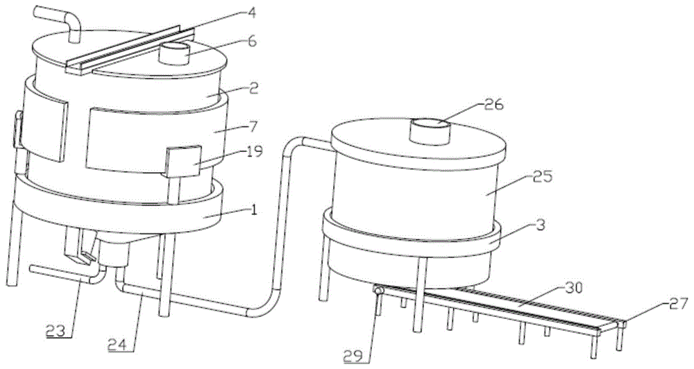
FIG. 1 is a schematic structural diagram of the present invention.
FIG. 2 is a schematic view of the structure of the purification module of the present invention.
Fig. 3 is a schematic structural view of fig. 2 without a tub cover installed.
FIG. 4 is a schematic view showing the connection between the stirring apparatus and the driving mechanism in the present invention.
FIG. 5 is a schematic view of the connection between the special-shaped connecting rod and the stirring rod in the present invention.
Fig. 6 is a schematic structural view of the conveying assembly of the present invention.
The device comprises a machine frame I, a machine frame II, a cross beam 4, a barrel cover 5, a sewage inlet 6, an electromagnet 7, a stirring device 8, a driving mechanism 9, a cylinder 10, a connecting piece 11, a motor 12, a base plate 13, a special-shaped connecting rod 14, a tooth 15, a stirring rod 16, a scraping plate 17, a motor 18, a support frame 19, a support frame 20, a vibration motor 21, a protective guard 22, a water discharging pipe 23, a discharging pipe 24, a drying furnace 25, a heat dissipation port 26, a support table 27, a roller 28, a motor 29 and a conveying belt 30.
Detailed Description
In order to make the technical means, the creation characteristics, the achievement purposes and the effects of the invention easy to understand, the invention is further described with the specific embodiments.
Examples
As shown in fig. 1 to 6, a dirt separating and recovering apparatus includes a cleaning assembly and a drying assembly;
the purification assembly comprises a frame I1, a purification barrel 2 is arranged on the frame I1, a beam 4 is arranged above the purification barrel 2, barrel covers 5 of the purification barrel 2 are symmetrically arranged on the beam 4 in a bilateral mode, a sewage inlet 6 is arranged on the barrel covers 5, a plurality of support frames 19 are arranged on the frame I1, two electromagnets 7 which are symmetrical in structure and encircle the outer wall of the purification barrel 2 are arranged on the plurality of support frames 19, a stirring device 8 which can change the state is arranged in the purification barrel 2, a driving mechanism 9 which drives the stirring device 8 to move is arranged below the beam 2, the driving mechanism 9 comprises a cylinder 10 arranged below the beam 2, a connecting piece 11 is arranged at the front end of a telescopic rod of the cylinder 10, a first motor 12 is arranged in the connecting piece 11, an output shaft of the first motor 12 is connected with the stirring device 8, and the lower end of the purification barrel 2 is communicated with a drain pipe 23 and a drain pipe 24 with a valve, the other end of the discharge pipe 24 is communicated to the drying component;
drying assembly carries out the drying to iron fillings, drying assembly includes frame two 3, be equipped with drying furnace 25 on frame two 3, drying furnace 25 upper end is equipped with thermovent 26, drying furnace 25 lower extreme is equipped with the bin outlet and carries the conveying assembly to the warehouse with the iron fillings after the drying.
In this embodiment, the stirring device 8 includes a base plate 13, one side of the base plate 13 is rotatably connected with two profile connecting rods 14 with symmetrical structures, the head of each profile connecting rod 14 is provided with a tooth 15, the tail of each profile connecting rod 14 is provided with a stirring rod 16, the outer side of each stirring rod 16 is provided with a scraping plate 17, the teeth 15 at the head of the two profile connecting rods 14 are meshed, the head of one profile connecting rod 14 is connected with an output shaft of a second motor 18, and the second motor 18 is installed at the other side of the base plate 13.
In this embodiment, 2 lower extremes of purification bucket are the back taper, 1 lower extreme linking bridge 20 of frame, install vibrating motor 21 on the support 20 and be used for vibrating purification bucket 2 lower extreme.
In this embodiment, guard rails 22 are installed on both sides of the cross beam 4.
In this embodiment, the conveying assembly includes a supporting table 27 installed at the lower end of the drying oven 25, a plurality of rollers 28 are rotatably connected to the supporting table 27, one roller is connected to a third motor 29, the third motor 29 is installed on the supporting table 27, and a conveyor belt 30 is connected to the plurality of rollers 28.
The output shaft of the first motor 12 is connected to the base plate 13.
The working process and principle are that sewage is introduced into the purification barrel 2 through the sewage inlet 6, the electromagnet 7 is electrified, scrap iron in the sewage is adsorbed on the inner wall of the purification barrel 2, the first motor 12 is started, the base plate 13, the special-shaped connecting rod 14 and the stirring rod 16 are driven to rotate, meanwhile, the air cylinder 10 is started, the telescopic rod on the air cylinder 10 drives the whole stirring device 8 to move up and down, the contact amount of the scrap iron in the sewage and the inner wall of the purification barrel 2 is increased, the adsorption amount of the scrap iron on the inner wall of the purification barrel 2 is increased, a valve on the drain pipe 23 is opened, and the sewage after the scrap iron is purified is discharged through the drain pipe 23; stopping leading sewage, powering off the electromagnet 7 when no sewage exists in the purifying barrel 2, starting the second motor 18 to rotate the special-shaped connecting rod 14 connected with the second motor, and starting the first motor 12 because the teeth 15 at the heads of the two special-shaped connecting rods 14 are meshed to ensure that the other special-shaped connecting rod 14 also rotates, and when the angle between the two special-shaped connecting rods 14 is increased to the maximum, the scraper 17 is in a vertical state, and the scraper 17 just contacts with the inner wall of the purifying barrel 2, and starting the first motor 12, the stirring rod 16 and the scraper 17 to rotate can scrape iron chips on the inner wall of the purifying barrel 2 down to the lower end of the purifying barrel 2, because the lower end of the purifying barrel 2 is in an inverted cone shape, and starting the vibrating motor 21 to vibrate the lower end of the purifying barrel 2, opening the valve on the discharging pipe 24 to discharge the iron chips from the discharging pipe 24, and the scraper 17 can be used for stirring sewage in the state change of the stirring device 8, and increasing the contact amount of the iron chips in the sewage and the inner wall of the purifying barrel 2, but also can be used for scraping scrap iron; arrange material pipe 24 and be connected with the pump, take out iron fillings and carry out the drying in the drying furnace 25, iron fillings after the drying are arranged to conveyer belt 30 through the bin outlet of drying furnace 25 lower extreme on, start No. three motor 29, drive roller 28 and rotate to make conveyer belt 30 motion carry dry iron fillings.
It will be appreciated by those skilled in the art that the invention may be embodied in other specific forms without departing from the spirit or essential characteristics thereof. The embodiments disclosed above are therefore to be considered in all respects as illustrative and not restrictive. All changes which come within the scope of or equivalence to the invention are intended to be embraced therein.