CN113320946B - Continuous FPC single pcs appearance defect inspection machine - Google Patents
Continuous FPC single pcs appearance defect inspection machine Download PDFInfo
- Publication number
- CN113320946B CN113320946B CN202110494924.1A CN202110494924A CN113320946B CN 113320946 B CN113320946 B CN 113320946B CN 202110494924 A CN202110494924 A CN 202110494924A CN 113320946 B CN113320946 B CN 113320946B
- Authority
- CN
- China
- Prior art keywords
- station
- material tray
- conveying
- detection
- tray
- Prior art date
- Legal status (The legal status is an assumption and is not a legal conclusion. Google has not performed a legal analysis and makes no representation as to the accuracy of the status listed.)
- Active
Links
- 238000007689 inspection Methods 0.000 title claims abstract description 20
- 230000007547 defect Effects 0.000 title claims abstract description 19
- 230000007246 mechanism Effects 0.000 claims abstract description 164
- 238000001514 detection method Methods 0.000 claims abstract description 104
- 230000007306 turnover Effects 0.000 claims abstract description 59
- 238000007599 discharging Methods 0.000 claims abstract description 6
- 230000000694 effects Effects 0.000 claims abstract description 4
- 230000000007 visual effect Effects 0.000 claims description 12
- 230000000712 assembly Effects 0.000 claims description 4
- 238000000429 assembly Methods 0.000 claims description 4
- 230000009471 action Effects 0.000 description 5
- 238000011144 upstream manufacturing Methods 0.000 description 4
- 238000011179 visual inspection Methods 0.000 description 4
- 238000010586 diagram Methods 0.000 description 1
- 230000004048 modification Effects 0.000 description 1
- 238000012986 modification Methods 0.000 description 1
- 230000009467 reduction Effects 0.000 description 1
Images



Classifications
-
- B—PERFORMING OPERATIONS; TRANSPORTING
- B65—CONVEYING; PACKING; STORING; HANDLING THIN OR FILAMENTARY MATERIAL
- B65G—TRANSPORT OR STORAGE DEVICES, e.g. CONVEYORS FOR LOADING OR TIPPING, SHOP CONVEYOR SYSTEMS OR PNEUMATIC TUBE CONVEYORS
- B65G47/00—Article or material-handling devices associated with conveyors; Methods employing such devices
- B65G47/22—Devices influencing the relative position or the attitude of articles during transit by conveyors
- B65G47/24—Devices influencing the relative position or the attitude of articles during transit by conveyors orientating the articles
- B65G47/248—Devices influencing the relative position or the attitude of articles during transit by conveyors orientating the articles by turning over or inverting them
-
- B—PERFORMING OPERATIONS; TRANSPORTING
- B65—CONVEYING; PACKING; STORING; HANDLING THIN OR FILAMENTARY MATERIAL
- B65G—TRANSPORT OR STORAGE DEVICES, e.g. CONVEYORS FOR LOADING OR TIPPING, SHOP CONVEYOR SYSTEMS OR PNEUMATIC TUBE CONVEYORS
- B65G15/00—Conveyors having endless load-conveying surfaces, i.e. belts and like continuous members, to which tractive effort is transmitted by means other than endless driving elements of similar configuration
- B65G15/30—Belts or like endless load-carriers
-
- B—PERFORMING OPERATIONS; TRANSPORTING
- B65—CONVEYING; PACKING; STORING; HANDLING THIN OR FILAMENTARY MATERIAL
- B65G—TRANSPORT OR STORAGE DEVICES, e.g. CONVEYORS FOR LOADING OR TIPPING, SHOP CONVEYOR SYSTEMS OR PNEUMATIC TUBE CONVEYORS
- B65G23/00—Driving gear for endless conveyors; Belt- or chain-tensioning arrangements
- B65G23/22—Arrangements or mountings of driving motors
-
- B—PERFORMING OPERATIONS; TRANSPORTING
- B65—CONVEYING; PACKING; STORING; HANDLING THIN OR FILAMENTARY MATERIAL
- B65G—TRANSPORT OR STORAGE DEVICES, e.g. CONVEYORS FOR LOADING OR TIPPING, SHOP CONVEYOR SYSTEMS OR PNEUMATIC TUBE CONVEYORS
- B65G43/00—Control devices, e.g. for safety, warning or fault-correcting
- B65G43/08—Control devices operated by article or material being fed, conveyed or discharged
-
- B—PERFORMING OPERATIONS; TRANSPORTING
- B65—CONVEYING; PACKING; STORING; HANDLING THIN OR FILAMENTARY MATERIAL
- B65G—TRANSPORT OR STORAGE DEVICES, e.g. CONVEYORS FOR LOADING OR TIPPING, SHOP CONVEYOR SYSTEMS OR PNEUMATIC TUBE CONVEYORS
- B65G47/00—Article or material-handling devices associated with conveyors; Methods employing such devices
- B65G47/74—Feeding, transfer, or discharging devices of particular kinds or types
-
- G—PHYSICS
- G01—MEASURING; TESTING
- G01N—INVESTIGATING OR ANALYSING MATERIALS BY DETERMINING THEIR CHEMICAL OR PHYSICAL PROPERTIES
- G01N21/00—Investigating or analysing materials by the use of optical means, i.e. using sub-millimetre waves, infrared, visible or ultraviolet light
- G01N21/84—Systems specially adapted for particular applications
- G01N21/88—Investigating the presence of flaws or contamination
- G01N21/95—Investigating the presence of flaws or contamination characterised by the material or shape of the object to be examined
- G01N21/956—Inspecting patterns on the surface of objects
Landscapes
- Engineering & Computer Science (AREA)
- Mechanical Engineering (AREA)
- Physics & Mathematics (AREA)
- Health & Medical Sciences (AREA)
- Life Sciences & Earth Sciences (AREA)
- Chemical & Material Sciences (AREA)
- Analytical Chemistry (AREA)
- Biochemistry (AREA)
- General Health & Medical Sciences (AREA)
- General Physics & Mathematics (AREA)
- Immunology (AREA)
- Pathology (AREA)
- Specific Conveyance Elements (AREA)
Abstract
The invention discloses a continuous FPC single pcs appearance defect inspection machine, which comprises a feeding station, a front detection station, a material covering disc station, a turnover station, a material taking disc station, a back detection station and a blanking station which are sequentially arranged; stacking and feeding mechanisms are arranged on the feeding station, the material covering disc station, the material taking disc station and the discharging station, moving detection mechanisms are arranged on the front detection station and the back detection station, and a turnover mechanism is arranged on the turnover station; this scheme is through material loading station, openly detect station, lid charging tray station, turn-over station, material taking disc station, back detection station and unloading station and cooperate in proper order, can realize the automatic detection in batches of FPC list pcs to can turn over automatically, guarantee that two faces of FPC list pcs can both obtain effective detection, improve efficiency, guaranteed detection effect.
Description
Technical Field
The invention relates to a continuous FPC single pcs appearance defect inspection machine, and belongs to the technical field of visual inspection equipment.
Background
After the FPC light board is produced, the FPC light board is cut into a plurality of single pcs units, and each single pcs unit needs to be inspected whether a product is qualified or not through visual inspection equipment; the existing mode is generally operated on detection equipment manually, single pcs units are detected one by one, the detection mode has low efficiency, especially the requirement of double-sided detection is required in some single pcs units, and the manual detection cannot meet the requirement of batch detection; the positioning accuracy of manual discharging is poor, and the detection effect is influenced; therefore, an automatic FPC single-pcs appearance defect inspection machine needs to be designed.
Disclosure of Invention
In view of the above technical problems, the present invention aims to: a continuous FPC single pcs appearance defect inspection machine is provided.
The technical solution of the invention is realized as follows: a continuous FPC single pcs appearance defect inspection machine comprises a feeding station, a front detection station, a material covering disc station, a turnover station, a material taking disc station, a back detection station and a discharging station which are sequentially arranged; stacking and feeding mechanisms are arranged on the feeding station, the material covering disc station, the material taking disc station and the discharging station, moving detection mechanisms are arranged on the front detection station and the back detection station, and a turnover mechanism is arranged on the turnover station; the stacking and feeding mechanism on the feeding station is used for conveying stacked material trays one by one to the mobile detection mechanism on the front detection station for detection; the moving detection mechanism on the front detection station conveys the detected material tray to the stacking and feeding mechanism on the material tray covering station; the stacking and feeding mechanism on the material covering disc station is used for placing a cover plate on the material disc and then feeding the cover plate into the turnover mechanism on the turnover station; the turnover mechanism turns over the cover plate and the material tray together to enable the workpiece in the material tray to be borne by the cover plate, and then the cover plate and the material tray are sent to the stacking and feeding mechanism on the material taking plate station; the stacking and feeding mechanism on the material taking plate station takes down the material plate and then sends the cover plate carrying the workpiece into the moving detection mechanism on the back detection station; the moving detection mechanism on the back detection station detects the workpiece on the cover plate and then sends the workpiece to the stacking and feeding mechanism on the blanking station; the stacking and feeding mechanism on the blanking station collects and stacks the cover plates loaded with the workpieces in sequence.
Preferably, the stacking and feeding mechanism comprises a material tray conveying mechanism, a material tray supporting mechanism and a material tray lifting mechanism; the material tray conveying mechanism is used for conveying a material tray or a cover plate, the material tray bearing mechanism is used for bearing the material tray or the cover plate, and the material tray lifting mechanism is used for driving the material tray or the cover plate to move between the material tray conveying mechanism and the material tray bearing mechanism.
Preferably, the material tray conveying mechanisms are arranged in two groups, the two groups of material tray conveying mechanisms are respectively positioned on two sides of the material tray lifting mechanism, and the two groups of material tray conveying mechanisms are oppositely arranged; the material tray conveying mechanism comprises a material tray conveying frame, a conveying driving motor and a material tray conveying belt, wherein the conveying driving motor and the material tray conveying belt are arranged on the material tray conveying frame, and the conveying driving motor drives the material tray conveying belt to run; the material tray supporting mechanisms are arranged in two groups, the two groups of material tray supporting mechanisms are respectively arranged at the upper sides of the two groups of material tray conveying mechanisms, and the two groups of material tray supporting mechanisms are oppositely arranged; the charging tray supporting mechanism comprises a side push cylinder and a side push supporting plate, and the side push cylinder drives the side push supporting plate to move; the material tray lifting mechanism comprises a material tray lifting driving device and a material tray support plate, and the material tray lifting driving device drives the material tray support plate to lift.
Preferably, a material tray matching and adjusting component is arranged between the two material tray conveying mechanisms and is used for adjusting the distance between the two material tray conveying mechanisms; the material tray conveying frame is also provided with a material stacking sensor and a stacking positioning frame, the material stacking sensor is used for detecting whether a material tray or a cover plate is arranged on the material tray supporting mechanism, and the positioning frame is matched with the corners of the material tray or the cover plate to play a role in positioning and guiding.
Preferably, the movement detection mechanism comprises a detection workbench frame, a detection forward movement mechanism, a visual detection assembly and a tray in-and-out mechanism; the detection forward moving mechanism and the tray in-and-out mechanism are arranged on the detection working rack; the detection forward moving mechanism is provided with a detection transverse moving mechanism, the detection forward moving mechanism drives the visual detection assembly to move forward and backward, and the detection transverse moving mechanism drives the visual detection assembly to move transversely; the tray in-and-out mechanism drives the material tray or the cover plate to transversely enter and exit, and the visual detection assembly detects workpieces on the material tray or the cover plate on the tray in-and-out mechanism.
Preferably, an operation table is arranged on the front side of the detection work table frame, and a display area and an operation area are arranged on the operation table.
Preferably, the turnover mechanism comprises a turnover base, a turnover driving device, a turnover frame, a conveying frame and a clamping assembly; the turnover driving device is arranged on the turnover base and drives the turnover frame to turn over; the material conveying device is characterized in that the overturning frame is provided with two groups of conveying frames and two groups of clamping assemblies, the two groups of conveying frames are arranged on the left side and the right side of the material conveying direction oppositely, and the two groups of clamping assemblies are arranged on the upper side and the lower side of the material conveying direction oppositely.
Preferably, the conveying frames are provided with conveying motors and conveying belts, and the conveying motors and the conveying belts on the two groups of conveying frames work synchronously.
Preferably, the clamping assembly comprises a cylinder frame, a clamping cylinder and a clamping plate, a guide rod is arranged on the roll-over stand, the cylinder frame is arranged on the guide rod in a sliding mode, the clamping cylinder is arranged on the cylinder frame, and the clamping cylinder drives the clamping plate to lift.
Preferably, the roll-over stand is provided with a conveying distance adjusting assembly, the two groups of conveying frames are matched with the conveying distance adjusting assembly, and the distance between the two groups of conveying frames is adjusted through the conveying distance adjusting assembly.
Due to the application of the technical scheme, compared with the prior art, the invention has the following advantages:
the continuous FPC single pcs appearance defect inspection machine of this scheme, through material loading station, openly detect the station, lid charging tray station, turn-over station, material taking disc station, back detection station and unloading station cooperate in proper order, can realize the automatic detection in batches of FPC single pcs to can turn over automatically, guarantee that two faces of FPC single pcs can both obtain effective detection, improve efficiency, guaranteed detection effect.
Drawings
The technical scheme of the invention is further explained by combining the accompanying drawings as follows:
FIG. 1 is a schematic view of a continuous FPC single pcs appearance defect inspection machine of the present invention;
FIG. 2 is a schematic structural view of a stacking and feeding mechanism according to the present invention;
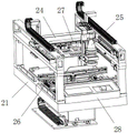
FIG. 3 is a schematic structural view of a movement detection mechanism according to the present invention;
fig. 4 is a schematic structural diagram of the turn-over mechanism of the present invention.
Detailed Description
The invention is described below with reference to the accompanying drawings.
As shown in the attached drawing 1, the continuous FPC single pcs appearance defect inspection machine comprises a feeding station 1, a front detection station 2, a cover material tray station 3, a turnover station 4, a material taking tray station 5, a back detection station 6 and a blanking station 7 which are sequentially arranged; all be provided with on material loading station 1, lid charging tray station 3, the material fetching disc station 5 and the unloading station 7 and pile up the mechanism of walking the material, all be provided with on positive detection station 2 and the back detection station 6 and remove detection mechanism, be provided with turn-over mechanism on the turn-over station 4.
As shown in fig. 2, the stacking and feeding mechanism comprises a tray conveying mechanism, a tray supporting mechanism and a tray lifting mechanism; the material tray conveying mechanism is used for conveying a material tray or a cover plate, the material tray bearing mechanism is used for bearing the material tray or the cover plate, and the material tray lifting mechanism is used for driving the material tray or the cover plate to lift so as to enable the material tray or the cover plate to move between the material tray conveying mechanism and the material tray bearing mechanism.
The two sets of material tray conveying mechanisms are respectively positioned at two sides of the material tray lifting mechanism and are oppositely arranged; the material tray conveying mechanism comprises a material tray conveying frame 41, a conveying driving motor 42 and a material tray conveying belt 43, the conveying driving motor 42 and the material tray conveying belt 43 are arranged on the material tray conveying frame 41, and the conveying driving motor 42 drives the material tray conveying belt 43 to run; the material tray supporting mechanisms are arranged in two groups, the two groups of material tray supporting mechanisms are respectively arranged at the upper sides of the two groups of material tray conveying mechanisms, and the two groups of material tray supporting mechanisms are oppositely arranged; the tray supporting mechanism comprises a side push cylinder 44 and a side push supporting plate 45, the side push cylinder 44 is installed on the tray conveying frame 41, and the side push cylinder 44 drives the side push supporting plate 45 to move; the tray lifting mechanism comprises a tray lifting driving device 46 and a tray support plate 47, the tray lifting driving device 46 is a motor, and the motor drives the tray support plate 47 to lift through a screw rod guide post and a lifting support.
A material tray matching and adjusting component 48 is arranged between the two groups of material tray conveying mechanisms, and the material tray matching and adjusting component 48 is used for adjusting the distance between the two groups of material tray conveying mechanisms so as to match material trays or cover plates with different specifications; the tray conveying frame 41 is also provided with a stacking sensor 49 and a stacking positioning frame 50, the stacking sensor 49 is used for detecting whether a tray or a cover plate is arranged on the tray supporting mechanism, and the stacking positioning frame 50 is matched with corners of the tray or the cover plate to play a role in positioning and guiding.
When the stacking and feeding mechanism on the feeding station 1 works, the stacked material trays are firstly placed on the two material tray supporting mechanisms, the two side pushing support plates 45 support the two sides of the lowest layer material tray, and the two sides of the material tray are provided with structures for the side pushing support plates 45 to be inserted; the material tray lifting driving device 46 drives the material tray support plate 47 to ascend and support the bottom of the material tray, the side pushing cylinder 44 drives the side pushing support plate 45 to retract, the material tray lifting driving device 46 drives the material tray support plate 47 to descend by the height of one material tray, the side pushing cylinder 44 drives the side pushing support plate 45 to extend, the side pushing support plate 45 supports two sides of the material tray on the penultimate layer, then the material tray support plate 47 continues to descend, two sides of the material tray on the lowest layer fall on the two material tray conveying mechanisms, and the two material tray conveying mechanisms synchronously work and convey the material tray to the next station; and then, continuously repeating the actions to sequentially convey the material trays.
As shown in fig. 3, the movement detection mechanism includes a detection work stage 21, a detection advance mechanism 24, a visual detection assembly 25, and a tray in-and-out mechanism 26; the detection forward moving mechanism 24 and the tray in-and-out mechanism 26 are arranged on the detection working table frame 21, the detection forward moving mechanism 24 adopts a motor lead screw truss structure, the detection forward moving mechanism 24 drives the visual detection assembly 25 to move back and forth, the detection forward moving mechanism 24 is provided with a detection transverse moving mechanism 27, and the detection transverse moving mechanism 27 drives the visual detection assembly 25 to move transversely.
The upstream station sends the material tray to the tray in-and-out mechanism 26, and then the visual inspection component 25 starts to move left and right, so as to perform visual inspection on all the workpieces on the material tray; an operation table 28 is arranged on the front side of the detection workbench frame 21, a display area and an operation area are arranged on the operation table 28, the operation area can control the position of the visual detection assembly 25, and the display area can feed back the detection result in time; after the detection is finished, the tray in-and-out mechanism 26 drives the material tray to move to the next station; the tray in-out mechanism 26 can adopt two sets of motor belt conveying mechanisms, the conveying direction is generally perpendicular to the grabbing direction of the tray, the two sets of conveying mechanisms respectively carry two sides of the material tray and synchronously operate, and the distance between the two sets of conveying mechanisms is adjustable so as to adapt to material trays with different sizes.
When the stacking and feeding mechanism on the material covering disc station 3 works, the stacked cover plates are firstly placed on the two material disc supporting mechanisms, the cover plates and the material discs have the same structure, the stacking and placing directions are opposite, and the two side pushing support plates 45 support two sides of the cover plate at the lowest layer; the tray lifting driving device 46 drives the tray support plate 47 to ascend to jack up the tray sent from an upstream station, the side push cylinder 44 drives the side push support plate 45 to retract, the cover plate falls by one layer, the cover plate at the lowest layer falls on the tray, the cover plate does not cover the tray and can abut against the workpiece in the tray at the same time, so that the workpiece is fixed and cannot be displaced; then the side-push cylinder 44 drives the side-push supporting plate 45 to extend out, so that the side-push supporting plate 45 supports two sides of the cover plate on the penultimate layer, then the tray supporting plate 47 descends, so that two sides of the tray fall on the two sets of tray conveying mechanisms, the two sets of tray conveying mechanisms synchronously work, and the tray with the cover plate is conveyed to the next station; and then, continuously repeating the actions to continuously place the cover plate on the material tray.
As shown in fig. 4, the turnover mechanism comprises a turnover base 31, a turnover driving device 32, a turnover frame 33, a conveying frame 34 and a clamping assembly; the turnover driving device 32 is arranged on the turnover base 31, the turnover base 31 can be arranged on two sides, the turnover driving device 32 can adopt a speed reduction motor, and the turnover driving device 32 drives the turnover frame 33 to turn over.
The roll-over stand 33 is provided with two groups of conveying frames 34 and two groups of clamping components, the two groups of conveying frames 34 are arranged oppositely on the left side and the right side of the material feeding direction, and the two groups of clamping components are arranged oppositely on the upper side and the lower side of the material feeding direction.
The conveying frames 34 are provided with conveying motors 35 and conveying belts, the conveying motors 35 and the conveying belts on the two groups of conveying frames 34 work synchronously, the turnover frame 33 is provided with a conveying distance adjusting assembly 39, the two groups of conveying frames 34 are matched with the conveying distance adjusting assembly 39, and the conveying distance adjusting assembly 39 is used for adjusting the distance between the two groups of conveying frames 34 so as to adapt to material trays with different sizes; the carriage 34 is also provided with a sensor for detecting whether the tray is in place.
The clamping assembly comprises a cylinder frame 36, a clamping cylinder 37 and a clamping plate 38, a guide rod is arranged on the turnover frame 33, the cylinder frame 36 is arranged on the guide rod in a sliding mode and can adjust the transverse position of the clamping plate 38, the clamping cylinder 37 is arranged on the cylinder frame 36, and the clamping cylinder 37 drives the clamping plate 38 to ascend and descend.
When the material tray is delivered from the upstream station to the right position, the upper clamping plate 38 and the lower clamping plate 38 move relatively close to each other to clamp the material tray and the cover plate, then the turnover driving device 32 drives the turnover frame 33 to turn over integrally, so that the material tray and the cover plate rotate for 180 degrees to turn over, then the upper clamping plate 38 and the lower clamping plate 38 return to enable the material tray and the cover plate to fall back onto the conveying frame 34, at the moment, the cover plate bears the workpiece on the lower side, the material tray covers the cover plate, and the conveying frame 34 drives the material tray and the cover plate to move to the next station.
When the stacking and feeding mechanism on the material taking station 5 works, the material tray lifting driving device 46 drives the material tray support plate 47 to lift up, the cover plate and the material tray sent from the upstream station are jacked up, the side push cylinder 44 drives the side push support plate 45 to retract, and the material tray support plate 47 rises by the height of one layer of the cover plate; then the side push cylinder 44 drives the side push support plate 45 to extend out, so that the side push support plate 45 supports two sides of the material tray, then the material tray support plate 47 drives the cover plate to descend, so that the cover plate is separated from the material tray, two sides of the cover plate fall on the two sets of material tray conveying mechanisms, the two sets of material tray conveying mechanisms synchronously work, and the cover plate is conveyed to the next station; and then, the above actions are repeated continuously, so that the material trays on the upper side of the cover plate can be unloaded upwards and stacked continuously.
The moving detection mechanism on the back detection station 6 has the same structure and the same action as the moving detection mechanism on the front detection station 2, the moving detection mechanism on the back detection station 6 detects the workpiece on the cover plate, and then the cover plate is sent to the stacking and feeding mechanism on the blanking station 7; the stacking and feeding mechanism on the blanking station 7 has the same structure as that of the stacking and feeding mechanism on the feeding station 1, and the actions are opposite, so that the cover plate can be jacked up and stacked to wait for manual or machine taking away of blanking.
The above-mentioned embodiments are merely illustrative of the technical idea and features of the present invention, and the purpose thereof is to enable those skilled in the art to understand the contents of the present invention and implement the present invention, and not to limit the scope of the present invention, and all equivalent changes or modifications made according to the spirit of the present invention should be covered in the scope of the present invention.
Claims (10)
1. The utility model provides a single pcs appearance imperfections inspection machine of continuous type FPC which characterized in that: the automatic material taking device comprises a feeding station (1), a front detection station (2), a material covering disc station (3), a turnover station (4), a material taking disc station (5), a back detection station (6) and a discharging station (7) which are arranged in sequence; stacking and feeding mechanisms are arranged on the feeding station (1), the material covering disc station (3), the material taking disc station (5) and the discharging station (7), moving detection mechanisms are arranged on the front detection station (2) and the back detection station (6), and a turnover mechanism is arranged on the turnover station (4); the stacking and feeding mechanism on the feeding station (1) is used for conveying stacked material trays one by one to the moving detection mechanism on the front detection station (2) for detection; the moving detection mechanism on the front detection station (2) conveys the detected material tray to the stacking material conveying mechanism on the material tray covering station (3); the stacking and feeding mechanism on the material covering disc station (3) is used for placing a cover plate on a material disc and then feeding the cover plate into the turnover mechanism on the turnover station (4); the turnover mechanism turns over the cover plate and the material tray together to enable workpieces in the material tray to be borne by the cover plate, and then the cover plate and the material tray are sent to the stacking and feeding mechanism on the material taking plate station (5); the stacking and feeding mechanism on the material taking plate station (5) takes down the material plate, and then the cover plate loaded with the workpiece is fed into the moving detection mechanism on the back detection station (6); the moving detection mechanism on the back detection station (6) detects the workpiece on the cover plate and then sends the workpiece to the stacking and feeding mechanism on the blanking station (7); and the stacking and feeding mechanism on the blanking station (7) collects and stacks the cover plates loaded with the workpieces in sequence.
2. The continuous FPC single pcs appearance defect inspection machine of claim 1, wherein: the stacking and feeding mechanism comprises a material tray conveying mechanism, a material tray supporting mechanism and a material tray lifting mechanism; the material tray conveying mechanism is used for conveying a material tray or a cover plate, the material tray bearing mechanism is used for bearing the material tray or the cover plate, and the material tray lifting mechanism is used for driving the material tray or the cover plate to move between the material tray conveying mechanism and the material tray bearing mechanism.
3. The continuous FPC single pcs appearance defect inspection machine of claim 2, wherein: the two sets of material tray conveying mechanisms are respectively positioned at two sides of the material tray lifting mechanism and are oppositely arranged; the material tray conveying mechanism comprises a material tray conveying frame (41), a conveying driving motor (42) and a material tray conveying belt (43), the conveying driving motor (42) and the material tray conveying belt (43) are arranged on the material tray conveying frame (41), and the conveying driving motor (42) drives the material tray conveying belt (43) to run; the material tray supporting mechanisms are arranged in two groups, the two groups of material tray supporting mechanisms are respectively arranged at the upper sides of the two groups of material tray conveying mechanisms, and the two groups of material tray supporting mechanisms are oppositely arranged; the tray supporting mechanism comprises a side pushing cylinder (44) and a side pushing supporting plate (45), and the side pushing cylinder (44) drives the side pushing supporting plate (45) to move; the material tray lifting mechanism comprises a material tray lifting driving device (46) and a material tray support plate (47), and the material tray lifting driving device (46) drives the material tray support plate (47) to lift.
4. The continuous FPC single pcs appearance defect inspection machine of claim 3, wherein: a material tray matching and adjusting component (48) is arranged between the two groups of material tray conveying mechanisms, and the material tray matching and adjusting component (48) is used for adjusting the distance between the two groups of material tray conveying mechanisms; still be provided with on charging tray carriage (41) and fold material sensor (49) and pile up locating rack (50), fold material sensor (49) and be used for detecting whether charging tray or apron still have on the charging tray supporting mechanism, pile up the corner cooperation of locating rack (50) and charging tray or apron, play the effect of location and direction.
5. The continuous FPC single pcs appearance defect inspection machine of claim 1, wherein: the movement detection mechanism comprises a detection working table frame (21), a detection forward moving mechanism (24), a visual detection assembly (25) and a tray in-out mechanism (26); the detection advancing mechanism (24) and the tray in-out mechanism (26) are arranged on the detection working rack (21); the detection forward moving mechanism (24) is provided with a detection transverse moving mechanism (27), the detection forward moving mechanism (24) drives the visual detection assembly (25) to move back and forth, and the detection transverse moving mechanism (27) drives the visual detection assembly (25) to move transversely; the tray in-out mechanism (26) drives the material tray or the cover plate to transversely enter and exit, and the visual detection assembly (25) detects the workpiece on the material tray or the cover plate on the tray in-out mechanism (26).
6. The continuous FPC single pcs appearance defect inspection machine of claim 5, wherein: an operation table (28) is arranged on the front side of the detection workbench frame (21), and a display area and an operation area are arranged on the operation table (28).
7. The continuous FPC single pcs appearance defect inspection machine of claim 1, wherein: the turnover mechanism comprises a turnover base (31), a turnover driving device (32), a turnover frame (33), a conveying frame (34) and a clamping assembly; the turnover driving device (32) is arranged on the turnover base (31), and the turnover driving device (32) drives the turnover frame (33) to turn over; the turnover frame (33) is provided with two groups of conveying frames (34) and two groups of clamping assemblies, the two groups of conveying frames (34) are arranged oppositely on the left side and the right side of the feeding direction, and the two groups of clamping assemblies are arranged oppositely on the upper side and the lower side of the feeding direction.
8. The continuous FPC single pcs appearance defect inspection machine of claim 7, wherein: the conveying frames (34) are provided with conveying motors (35) and conveying belts, and the conveying motors (35) and the conveying belts on the two groups of conveying frames (34) work synchronously.
9. The continuous FPC single pcs appearance defect inspection machine of claim 7, wherein: the clamping assembly comprises a cylinder frame (36), a clamping cylinder (37) and a clamping plate (38), a guide rod is arranged on the turnover frame (33), the cylinder frame (36) is arranged on the guide rod in a sliding mode, the clamping cylinder (37) is arranged on the cylinder frame (36), and the clamping cylinder (37) drives the clamping plate (38) to lift.
10. The continuous FPC single pcs appearance defect inspection machine of claim 7, wherein: the overturning frame (33) is provided with a conveying distance adjusting assembly (39), the two groups of conveying frames (34) are matched with the conveying distance adjusting assembly (39), and the distance between the two groups of conveying frames (34) is adjusted through the conveying distance adjusting assembly (39).
Priority Applications (1)
| Application Number | Priority Date | Filing Date | Title |
|---|---|---|---|
| CN202110494924.1A CN113320946B (en) | 2021-05-07 | 2021-05-07 | Continuous FPC single pcs appearance defect inspection machine |
Applications Claiming Priority (1)
| Application Number | Priority Date | Filing Date | Title |
|---|---|---|---|
| CN202110494924.1A CN113320946B (en) | 2021-05-07 | 2021-05-07 | Continuous FPC single pcs appearance defect inspection machine |
Publications (2)
| Publication Number | Publication Date |
|---|---|
| CN113320946A CN113320946A (en) | 2021-08-31 |
| CN113320946B true CN113320946B (en) | 2022-03-29 |
Family
ID=77414213
Family Applications (1)
| Application Number | Title | Priority Date | Filing Date |
|---|---|---|---|
| CN202110494924.1A Active CN113320946B (en) | 2021-05-07 | 2021-05-07 | Continuous FPC single pcs appearance defect inspection machine |
Country Status (1)
| Country | Link |
|---|---|
| CN (1) | CN113320946B (en) |
Families Citing this family (6)
| Publication number | Priority date | Publication date | Assignee | Title |
|---|---|---|---|---|
| CN114516530B (en) * | 2022-03-25 | 2025-04-29 | 深圳市联合东创科技有限公司 | FPC cable loading and unloading device |
| CN114939538B (en) * | 2022-05-20 | 2023-04-07 | 深圳市标谱半导体股份有限公司 | Front and back detection equipment |
| CN115744222B (en) * | 2022-09-27 | 2025-12-19 | 芜湖市欣龙机械有限责任公司 | Loading attachment for stamping workpiece check out test set based on |
| CN115656195A (en) * | 2022-09-30 | 2023-01-31 | 海宁上通优必胜轴承有限公司 | Bearing ring surface flaw detection device based on visual inspection |
| CN117068547A (en) * | 2023-09-01 | 2023-11-17 | 西安西电变压器有限责任公司 | A kind of transfer tooling and transfer method for transformer core sheets |
| CN119637222A (en) * | 2024-11-26 | 2025-03-18 | 盐城维信电子有限公司 | Multi-line flexo plate flipping device and flexo plate flipping method |
Family Cites Families (5)
| Publication number | Priority date | Publication date | Assignee | Title |
|---|---|---|---|---|
| CN203011848U (en) * | 2012-11-02 | 2013-06-19 | 晶彩科技股份有限公司 | Panel inspection device with flip mechanism |
| CN205634163U (en) * | 2016-05-04 | 2016-10-12 | 上海凯思尔电子有限公司 | A automatic collecting and releasing plate machine of AOI for PCB production facility |
| CN116969153A (en) * | 2018-11-29 | 2023-10-31 | 深圳宜美智科技股份有限公司 | FPC board switching system and corresponding FPC board outward appearance detects machine |
| CN110554057B (en) * | 2019-09-18 | 2024-05-17 | 深圳市深科达智能装备股份有限公司 | Full-automatic detection equipment for appearance of screen cover plate |
| CN211846318U (en) * | 2019-10-21 | 2020-11-03 | 索亿智能装备(东莞)有限公司 | Intelligent disassembly device |
-
2021
- 2021-05-07 CN CN202110494924.1A patent/CN113320946B/en active Active
Also Published As
| Publication number | Publication date |
|---|---|
| CN113320946A (en) | 2021-08-31 |
Similar Documents
| Publication | Publication Date | Title |
|---|---|---|
| CN113320946A (en) | Continuous FPC single pcs appearance defect inspection machine | |
| CN113697513B (en) | Layered tray layered feeding device | |
| CN112520413B (en) | Full-automatic aging test loading and unloading system and method | |
| CN111900115B (en) | A feeding device for a solar cell rewinding machine | |
| CN109834448A (en) | Battery of mobile phone automatic assembling | |
| CN109894739A (en) | Fully-automatic laser marking press equipment for cylinder circle | |
| CN110538806A (en) | detection system and feeding and discharging equipment thereof | |
| CN220200662U (en) | An efficient tray automatic loading and unloading equipment | |
| CN108808100A (en) | Lithium battery pole ear bonding machine | |
| CN111302064B (en) | Precision feeding device for laser scribing machine | |
| CN219807285U (en) | Material box carrying and connecting device | |
| CN113320947B (en) | Three-station FPC single pcs appearance defect inspection machine | |
| CN110723534A (en) | Automatic screen separating machine | |
| CN212793807U (en) | LED lamp plate drain pan kludge based on robot | |
| CN110369887B (en) | A tray feeding device | |
| CN116040311A (en) | Prism product sheet arranging equipment | |
| CN116470709A (en) | Rotary lamination assembly system for stator core production | |
| CN212638976U (en) | Double-bin feeding mechanism | |
| CN222203998U (en) | Loading and unloading device and chip test automatic separation equipment | |
| CN215207285U (en) | Be used for product testing to receive unloading mechanism on charging tray | |
| CN216784881U (en) | Face ID module unloader | |
| CN117923175A (en) | Automatic feeding and discharging device for material tray | |
| CN114104403B (en) | a delivery system | |
| CN116835293A (en) | Automatic feeding and discharging equipment and method for efficient Tray | |
| CN213905300U (en) | Process terminal detection equipment |
Legal Events
| Date | Code | Title | Description |
|---|---|---|---|
| PB01 | Publication | ||
| PB01 | Publication | ||
| SE01 | Entry into force of request for substantive examination | ||
| SE01 | Entry into force of request for substantive examination | ||
| GR01 | Patent grant | ||
| GR01 | Patent grant |