CN113305271A - Novel sand casting equipment and casting method thereof - Google Patents
Novel sand casting equipment and casting method thereof Download PDFInfo
- Publication number
- CN113305271A CN113305271A CN202110511516.2A CN202110511516A CN113305271A CN 113305271 A CN113305271 A CN 113305271A CN 202110511516 A CN202110511516 A CN 202110511516A CN 113305271 A CN113305271 A CN 113305271A
- Authority
- CN
- China
- Prior art keywords
- sand
- casting
- box
- fixedly connected
- wall
- Prior art date
- Legal status (The legal status is an assumption and is not a legal conclusion. Google has not performed a legal analysis and makes no representation as to the accuracy of the status listed.)
- Granted
Links
- 238000005266 casting Methods 0.000 title claims abstract description 67
- 238000007528 sand casting Methods 0.000 title claims abstract description 36
- 238000000034 method Methods 0.000 title abstract description 13
- 239000004576 sand Substances 0.000 claims abstract description 132
- 238000003756 stirring Methods 0.000 claims description 42
- 238000007790 scraping Methods 0.000 claims description 26
- 238000002156 mixing Methods 0.000 claims description 8
- 230000000149 penetrating effect Effects 0.000 claims description 7
- 238000012216 screening Methods 0.000 claims description 7
- 230000005540 biological transmission Effects 0.000 claims description 3
- 238000007873 sieving Methods 0.000 claims 1
- 239000003110 molding sand Substances 0.000 abstract description 36
- 238000004519 manufacturing process Methods 0.000 abstract description 7
- 239000002699 waste material Substances 0.000 abstract description 3
- 238000004064 recycling Methods 0.000 abstract description 2
- 230000000694 effects Effects 0.000 description 25
- 238000007906 compression Methods 0.000 description 10
- 230000006835 compression Effects 0.000 description 10
- 239000004744 fabric Substances 0.000 description 8
- 239000002994 raw material Substances 0.000 description 7
- 238000000465 moulding Methods 0.000 description 4
- 238000004140 cleaning Methods 0.000 description 3
- 238000003825 pressing Methods 0.000 description 3
- 244000035744 Hura crepitans Species 0.000 description 2
- XEEYBQQBJWHFJM-UHFFFAOYSA-N Iron Chemical compound [Fe] XEEYBQQBJWHFJM-UHFFFAOYSA-N 0.000 description 2
- 238000010586 diagram Methods 0.000 description 2
- 239000007788 liquid Substances 0.000 description 2
- 238000007670 refining Methods 0.000 description 2
- 239000007787 solid Substances 0.000 description 2
- 229910000831 Steel Inorganic materials 0.000 description 1
- 238000010923 batch production Methods 0.000 description 1
- 230000009286 beneficial effect Effects 0.000 description 1
- 238000005056 compaction Methods 0.000 description 1
- 230000003031 feeding effect Effects 0.000 description 1
- 238000005429 filling process Methods 0.000 description 1
- 229910052742 iron Inorganic materials 0.000 description 1
- 238000005058 metal casting Methods 0.000 description 1
- 239000000203 mixture Substances 0.000 description 1
- 239000012778 molding material Substances 0.000 description 1
- 238000011084 recovery Methods 0.000 description 1
- 238000005507 spraying Methods 0.000 description 1
- 239000010959 steel Substances 0.000 description 1
Images



Classifications
-
- B—PERFORMING OPERATIONS; TRANSPORTING
- B22—CASTING; POWDER METALLURGY
- B22C—FOUNDRY MOULDING
- B22C15/00—Moulding machines characterised by the compacting mechanism; Accessories therefor
- B22C15/10—Compacting by jarring devices only
- B22C15/12—Compacting by jarring devices only involving mechanical gearings
-
- B—PERFORMING OPERATIONS; TRANSPORTING
- B22—CASTING; POWDER METALLURGY
- B22C—FOUNDRY MOULDING
- B22C23/00—Tools; Devices not mentioned before for moulding
-
- B—PERFORMING OPERATIONS; TRANSPORTING
- B22—CASTING; POWDER METALLURGY
- B22C—FOUNDRY MOULDING
- B22C5/00—Machines or devices specially designed for dressing or handling the mould material so far as specially adapted for that purpose
- B22C5/04—Machines or devices specially designed for dressing or handling the mould material so far as specially adapted for that purpose by grinding, blending, mixing, kneading, or stirring
Landscapes
- Engineering & Computer Science (AREA)
- Mechanical Engineering (AREA)
- Casting Devices For Molds (AREA)
Abstract
The invention belongs to the technical field of sand casting devices, in particular to novel sand casting equipment and a casting method thereof, aiming at the problems of large consumption of manual labor strength and production time cost, low working efficiency, poor casting mold precision, lack of corresponding batching function, resulting in sand filling trouble, recycling trouble of excessive molding sand overflowing during sand filling and reduction of waste sand utilization rate in the prior art, the invention provides the following scheme, which comprises a casting box, wherein four corners of the outer wall of the bottom of the casting box are respectively provided with a supporting leg, the bottom of the casting box is provided with a sand unloading pipe, and a sand unloading valve is arranged on the sand unloading pipe. The degree of automation is high, has reduced manual operation intensity, has improved the casting mould precision.
Description
Technical Field
The invention relates to the technical field of sand casting devices, in particular to novel sand casting equipment and a casting method thereof.
Background
Sand casting is a casting process that produces castings in sand molds. Steel, iron and most nonferrous metal castings can be obtained by sand casting. The molding material used for sand casting is cheap and easy to obtain, the casting mould is simple and convenient to manufacture, and the casting mould can adapt to single-piece production, batch production and mass production of castings, and is a basic process in casting production for a long time.
The traditional sand casting is mostly manual molding, and the specific molding process comprises the steps of putting a mold of a sand casting device into red sand for burying, taking out the mold, scraping the plane of the mold, spraying parting sand, putting a sand box, manually adding a pouring gate and a riser, putting the red sand for tamping, taking out an upper molding sand box, taking out the pouring gate and the riser, taking out a lower molding mold, and finally closing the mold.
Traditional hand modeling consumes a large amount of manual labor physical power and production time cost through sand filling, sand pressing and sand scraping processes, and work efficiency is low, and the casting mould precision is poor, lacks corresponding batching function moreover, and it is troublesome to lead to sand filling, and the unnecessary molding sand recycle that spills over when sand filling simultaneously is troublesome, reduces useless sand utilization ratio, therefore we have proposed a novel sand casting equipment for solve the above-mentioned problem that proposes.
Disclosure of Invention
The invention aims to solve the problems that in the prior art, a large amount of manual labor force and production time cost are consumed, the working efficiency is low, the casting mold precision is poor, a corresponding batching function is lacked, so that sand filling is troublesome, and meanwhile, the recovery and utilization of excessive molding sand overflowing during sand filling are troublesome, so that the utilization rate of waste sand is reduced.
In order to achieve the purpose, the invention adopts the following technical scheme:
a novel sand casting device comprises a casting box, wherein four corners of the outer wall of the bottom of the casting box are respectively provided with a supporting leg, the bottom of the casting box is provided with a sand unloading pipe, a sand unloading valve is mounted on the sand unloading pipe, one side of the outer wall of the top of the casting box is fixedly connected with a batching box through a cushion block, the top of the batching box is symmetrically provided with two feeding pipes, the bottom of the batching box is provided with a sand conveying pipe, the bottom end of the sand conveying pipe penetrates through the top of the casting box, the sand conveying pipe is provided with a sand conveying valve, the batching box is internally provided with a stirring assembly, the inner wall of one side of the casting box, which is far away from each other, is symmetrically and fixedly connected with two connecting blocks, one side of the two connecting blocks, which is close to each other, is fixedly connected with the same U-shaped fixing seat, the top of the U-shaped fixing seat is in sliding contact with a sliding table, and the two sides of the sliding table respectively extend to the outer sides of the long edges of the two sides of the U-shaped fixing seat, the inner side of the U-shaped fixing seat is provided with a power assembly for driving the sliding table to slide back and forth, the movable joint in top of slip table has the sand frame the same with the surface area size of slip table, and the sand frame is located and send the sand pipe under, the symmetry of one side outer wall that the sand frame kept away from each other is equipped with two handles, one side of casting box is equipped with the chamber door that is located adjacent connecting block top, one side sliding connection that the chamber door was kept away from to the top inner wall of casting box has the sieve sand subassembly that is located and send the sand pipe below, and sieve sand subassembly and stirring subassembly cooperate, one side sliding connection that the top inner wall of casting box is close to the chamber door has the subassembly of scraping sand.
Preferably, the stirring subassembly is including being the (mixing) shaft of horizontal rotation connection in the batching incasement portion, the symmetry is equipped with a plurality of stirring vane on the (mixing) shaft, top outer wall one side fixedly connected with agitator motor of foundry sand case, agitator motor's output shaft and the bottom of the one side outer wall that the batching case is close to the chamber door rotate to be connected, and one side of (mixing) shaft extends to the outside of batching case and is connected with same belt with agitator motor's output shaft transmission, start agitator motor, can drive the (mixing) shaft through the belt and rotate, and then realize the effect to the batching stirring through the stirring vane is rotatory.
Preferably, two the top of connecting block all is the triangle and describes the setting, is the setting of triangle point form through the top of connecting block, can prevent that the molding sand that falls from piling up, reduces artificial clearance intensity.
Preferably, the power assembly comprises a first lead screw rotatably connected to the inner wall of one side of the U-shaped fixing seat, which is far away from the box door, the other end of the first lead screw is fixedly connected with a first lead screw motor, the first lead screw motor is fixedly installed on the inner wall of one side of the U-shaped fixing seat, which is near to the box door, one side of the first lead screw is in threaded sleeve connection with a rectangular nut plate, one side, which is far away from each other, of the rectangular nut plate is fixedly connected with a vertical plate, the tops of the two vertical plates are respectively and fixedly connected with two sides, which extend from the bottom of the sliding table to the outer side of the U-shaped fixing seat, the top of one side, which is near to each other, of the two vertical plates is fixedly connected with a T-shaped sliding groove, the two T-shaped sliding blocks are respectively and slidably connected in the two T-shaped sliding grooves, the rectangular nut plate is driven by starting the first lead screw motor to move back and forth, the sliding table can be driven by the vertical plates to move back and forth, thereby realizing the effect of the back and forth movement of the sand frame.
Preferably, four angles in bottom of sand frame all are equipped with the reference column, and four angles in top of slip table all are equipped with the constant head tank, and four reference columns respectively with four constant head tank activity joint cooperations, through the joint cooperation of reference column and constant head tank, can play the stable effect of placing in location to sand frame.
Preferably, the sieve sand subassembly includes the screen cloth of sliding connection in cast sand roof portion inner wall one side and the fixed block of fixed connection in cast sand roof portion inner wall one side, two slide bars of one side outer wall symmetry fixedly connected with of chamber door are kept away from to the screen cloth, and one side of two slide bars runs through sliding connection with one side of fixed block respectively, the cover is all run through to one side of two slide bars and is equipped with reset spring, and one side fixed connection that respectively is close to each other with screen cloth and fixed block is equallyd divide at two reset spring's both ends, can play the gliding effect of support to the screen cloth through the slide bar, improve gliding stability, can play the effect that resets to the screen cloth through reset spring simultaneously.
Preferably, one side that the screen cloth is close to the chamber door rotates and is connected with the connecting rod, the fixed cover in one side that agitator motor's output shaft is close to the batching box is equipped with the cam, sliding connection has a movable rod to run through on one side of the top of foundry sand case, the top of movable rod extends to the top of foundry sand case and cooperatees with the cam, the bottom of movable rod extends to the inside of foundry sand case and is connected with the other end rotation of connecting rod, drive the cam through starting agitator motor and rotate and with movable rod movable contact, can drive the screen cloth through the connecting rod and remove, and realize the effect of screen cloth vibration back and forth through the cooperation with reset spring.
Preferably, the sand scraping assembly comprises a second lead screw which is rotatably connected to the upper portion inside the sand casting box and parallel to the short edge of the U-shaped fixed seat, one end of the second lead screw penetrates through the top of one side of the sand casting box and is fixedly connected with a second lead screw motor, a U-shaped nut plate is sleeved on one side of the second lead screw in a threaded manner, the top of the U-shaped nut plate is connected with the inner wall of the top of the sand casting box in a sliding manner, and the U-shaped nut plate can be driven to slide back and forth by starting the second lead screw motor.
Preferably, one side bottom symmetry that U type nut plate is close to second lead screw motor is equipped with two pieces, and two pieces rotate one side that is close to each other and are connected with same roller, and fixed cover is equipped with the compression roller that is located sand frame top one side on the roller, can drive the compression roller through the removal of U type nut plate and remove to this can realize playing the compaction effect to the molding sand that fills up on the sand frame.
Preferably, the inner walls of the two sides of the U-shaped nut plate are rotatably connected with the same rotating rod, one side of the rotating rod is fixedly sleeved with a rotating block, the bottom of the rotating block extends to the lower part of the U-shaped nut plate and is fixedly connected with a scraper, the bottom of the scraper is lower than the top of the sand frame, the scraper is arranged in an inverted triangle, torsion springs are respectively sleeved on two sides of the rotating rod, which are positioned on the rotating block, the ends, which are far away from each other, of the two torsion springs are respectively fixedly connected with the inner walls of two sides of the U-shaped nut plate, the ends, which are close to each other, of the two torsion springs are respectively fixedly connected with the side, which is far away from each other, of the rotating block, the scraper is driven to move by the movement of the U-shaped nut plate and is in rotary, can realize striking off the unnecessary molding sand in sand frame top, can play the effect of supporting tightly and reseing to the scraper blade through torque spring, can also realize two-sided scraping back and forth simultaneously, improve the planarization of scraping sand.
The invention has the beneficial effects that:
1. the feeding effect of solid raw materials and liquid raw materials in a classification mode can be achieved through the two feeding pipes, the stirring motor is started, the stirring shaft can be driven to rotate through the belt, the stirring blades are further driven to rotate, the raw materials are stirred and mixed, and therefore the blending process of molding sand is completed;
2. the sand frame can be positioned and placed on the sliding table through the clamping matching of the positioning column and the positioning groove, the first lead screw is driven to rotate by starting the first lead screw motor, the rectangular nut plate can be driven to move leftwards, the two vertical plates are driven to slide leftwards, the sliding table is driven to move leftwards, and the sand frame is driven to move to the lower side of the screen, so that the sand filling process is facilitated, the sand filling and scraping processes can be switched, and the automation degree is improved;
3. the stirring motor can also drive the cam to rotate and can drive the movable rod to move downwards when the cam is contacted with the movable rod, the connecting rod can drive the screen to move leftwards and drive the sliding rod to slide leftwards, when the cam is separated from the movable rod, the screen can be reset rightwards under the elastic action of the reset spring, and then the connecting rod drives the movable rod to reset upwards, so that the vibration effect of the screen is realized, the refining of the molding sand is achieved, and the uniformity of the sand filling can be improved through the vibrating screen;
4. one part of redundant molding sand directly falls into the bottom inside the casting box, one part of the redundant molding sand falls into the top of the U-shaped fixed seat, the top of the connecting block is arranged in a triangular pointed shape, the falling molding sand can be prevented from being accumulated, the manual cleaning strength is reduced, and the molding sand on the U-shaped fixed seat can be pushed to the bottom inside the casting box for centralized collection through the back-and-forth movement of the sliding table, so that the waste sand can be recycled, and the utilization rate is greatly improved;
5. the second screw rod motor is started to drive the second screw rod to rotate, so that the U-shaped nut plate can be driven to move, the compression roller and the scraper plate are driven to move, the compression roller is firstly compressed and pushed with molding sand in the sand frame, the scraper plate is in abutting contact with the top of the sand frame, the effect of scraping the molding sand is further achieved, when the U-shaped nut plate moves back and forth, the effect of scraping the molding sand on two sides can be achieved, and the scraping flatness is improved;
6. through the setting of U type fixing base, can prevent that the molding sand from falling and causing the damage to it on first lead screw and first lead screw motor, influence its normal work.
According to the invention, the stirring function of the batching box can be realized by starting the stirring motor, so that batching is facilitated, and the screen can be driven to move back and forth when sand is filled, so that the vibration effect is realized, so that the molding sand is refined, the casting mold effect is improved, the position of the sand frame can be adjusted by starting the first lead screw motor, the sand pressing and scraping processes after sand filling are facilitated, the pressing roller and the scraper can be driven to move by starting the second lead screw motor, so that the compression and scraping effects on the molding sand can be realized, the automation degree is high, the manual operation intensity is reduced, the casting mold precision is improved, meanwhile, the collection of redundant molding sand can be realized through the casting box, so that the recycling is facilitated, and the practicability is greatly improved.
Drawings
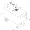
FIG. 1 is a perspective view of the overall structure of a novel sand casting device according to the present invention;
FIG. 2 is an enlarged view of part A of the novel sand casting equipment provided by the invention;
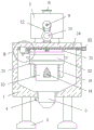
FIG. 3 is a front sectional view of the overall structure of a novel sand casting device according to the present invention;
FIG. 4 is a schematic structural diagram of a sand screening assembly of the novel sand casting device according to the present invention;
FIG. 5 is a perspective view of a connecting structure of a U-shaped fixing seat and a sliding table of the novel sand casting device provided by the invention;
FIG. 6 is a perspective view of a sand frame of the sand casting apparatus according to the present invention;
FIG. 7 is a schematic structural diagram of a sand scraping assembly of the novel sand casting device according to the present invention;
FIG. 8 is a right sectional view of the overall structure of a novel sand casting device according to the present invention;
FIG. 9 is an enlarged view of part B of the novel sand casting equipment according to the present invention;
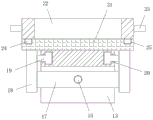
fig. 10 is a side sectional view of a connection structure of a U-shaped fixing seat and a sliding table of the novel sand casting device according to the present invention.
In the figure: 1. a casting box; 2. supporting legs; 3. unloading the sand pipe; 4. a sand discharge valve; 5. a batching box; 6. a feed pipe; 7. a sand conveying pipe; 8. a sand feeding valve; 9. a stirring shaft; 10. a stirring blade; 11. a stirring motor; 12. a belt; 13. a U-shaped fixed seat; 14. connecting blocks; 15. a first lead screw; 16. a first lead screw motor; 17. a rectangular nut plate; 18. a vertical plate; 19. a T-shaped slider; 20. a T-shaped chute; 21. a sliding table; 22. a sand frame; 23. a handle; 24. a positioning column; 25. positioning a groove; 26. a box door; 27. screening a screen; 28. a fixed block; 29. a slide bar; 30. a return spring; 31. a movable rod; 32. a connecting rod; 33. a cam; 34. a second lead screw; 35. a second lead screw motor; 36. a U-shaped nut plate; 37. supporting a block; 38. a roll shaft; 39. a compression roller; 40. a rotating rod; 41. rotating the block; 42. a squeegee; 43. a torsion spring.
Detailed Description
The technical solutions in the embodiments of the present invention will be clearly and completely described below with reference to the drawings in the embodiments of the present invention, and it is obvious that the described embodiments are only a part of the embodiments of the present invention, and not all of the embodiments.
Example one
Referring to fig. 1-10, a novel sand casting device and a casting method thereof, comprising a casting box 1, wherein four corners of the outer wall of the bottom of the casting box 1 are all provided with supporting legs 2, the bottom of the casting box 1 is provided with a sand unloading pipe 3, the sand unloading pipe 3 is provided with a sand unloading valve 4, one side of the outer wall of the top of the casting box 1 is fixedly connected with a proportioning box 5 through a cushion block, the top of the proportioning box 5 is symmetrically provided with two feeding pipes 6, the bottom of the proportioning box 5 is provided with a sand feeding pipe 7, the bottom end of the sand feeding pipe 7 penetrates through the top of the casting box 1, the sand feeding pipe 7 is provided with a sand feeding valve 8, the proportioning box 5 is internally provided with a stirring component, the inner wall of the side of the casting box 1 far away from each other is symmetrically and fixedly connected with two connecting blocks 14, the side of the two connecting blocks 14 close to each other, and the both sides of slip table 21 extend to the outside that is located the long limit in U type fixing base 13 both sides respectively, the inboard of U type fixing base 13 is equipped with and is used for driving slip table 21 gliding power component that makes a round trip, the top activity joint of slip table 21 has the sand frame 22 the same with the surface area size of slip table 21, and sand frame 22 is located and send sand pipe 7 under, the outside wall symmetry of one side that sand frame 22 kept away from each other is equipped with two handles 23, one side of foundry sand case 1 is equipped with the chamber door 26 that is located adjacent connecting block 14 top, one side sliding connection that the chamber door 26 was kept away from to the top inner wall of foundry sand case 1 has the screening sand subassembly that is located and send sand pipe 7 below, and screening sand subassembly and stirring subassembly cooperate, one side sliding connection that the top inner wall of foundry sand case 1 is close to chamber door 26 has the scraping sand subassembly.
According to the invention, the stirring component comprises a stirring shaft 9 which is transversely and rotatably connected inside the batching box 5, a plurality of stirring blades 10 are symmetrically arranged on the stirring shaft 9, a stirring motor 11 is fixedly connected to one side of the outer wall of the top of the casting box 1, the output shaft of the stirring motor 11 is rotatably connected with the bottom of the outer wall of one side, close to the box door 26, of the batching box 5, one side of the stirring shaft 9 extends to the outer side of the batching box 5 and is in transmission connection with the same belt 12 as the output shaft of the stirring motor 11, the stirring motor 11 is started, the stirring shaft 9 can be driven to rotate through the belt 12, and then the effect of stirring the batching is realized through the rotation of the stirring blades 10.
According to the invention, the tops of the two connecting blocks 14 are both arranged in a triangular pointed shape, and the tops of the connecting blocks 14 are arranged in a triangular pointed shape, so that falling molding sand can be prevented from being accumulated, and the manual cleaning strength is reduced.
In the invention, the power component comprises a first screw rod 15 which is rotatably connected with the inner wall of one side of the U-shaped fixed seat 13 far away from the box door 26, the other end of the first screw rod 15 is fixedly connected with a first screw rod motor 16, the first screw rod motor 16 is fixedly arranged on the inner wall of one side of the U-shaped fixed seat 13 near the box door 26, one side of the first screw rod 15 is sheathed with a rectangular nut plate 17 in a threaded manner, the mutually far sides of the rectangular nut plates 17 are fixedly connected with vertical plates 18, the top parts of the two vertical plates 18 are respectively and fixedly connected with the two sides of the bottom part of the sliding table 21 extending to the outer side of the U-shaped fixed seat 13, the top parts of the mutually near sides of the two vertical plates 18 are respectively and fixedly connected with a T-shaped sliding block 19, the mutually far sides of the U-shaped fixed seat 13 are respectively provided with a T-shaped sliding groove 20, and the two T-shaped sliding blocks 19 are respectively and are slidably connected in the two T-shaped sliding grooves 20, and the rectangular nut plate 17 is driven to move back and forth by starting the first screw rod motor 16, the sliding table 21 can be driven by the vertical plate 18 to move back and forth, so that the effect of back and forth movement of the sand frame 22 is realized.
In the invention, four corners at the bottom of the sand frame 22 are respectively provided with positioning columns 24, four corners at the top of the sliding table 21 are respectively provided with positioning grooves 25, the four positioning columns 24 are respectively in movable clamping fit with the four positioning grooves 25, and the sand frame 22 can be stably positioned and placed by the clamping fit of the positioning columns 24 and the positioning grooves 25.
According to the invention, the sand screening component comprises a screen 27 connected to one side of the inner wall of the top of the casting box 1 in a sliding manner and a fixed block 28 fixedly connected to one side of the inner wall of the top of the casting box 1, two sliding rods 29 are symmetrically and fixedly connected to the outer wall of one side, far away from the box door 26, of the screen 27, one sides of the two sliding rods 29 are respectively connected with one sides of the fixed block 28 in a penetrating and sliding manner, return springs 30 are respectively sleeved on one sides of the two sliding rods 29 in a penetrating manner, two ends of each return spring 30 are respectively fixedly connected with one side, close to the screen 27 and the other side, of the fixed block 28, the sliding rod 29 can play a supporting and sliding effect on the screen 27, the sliding stability is improved, and meanwhile, the return spring 30 can play a resetting effect on the screen 27.
In the invention, a connecting rod 32 is rotatably connected to one side of the screen 27 close to the door 26, a cam 33 is fixedly sleeved on one side of an output shaft of the stirring motor 11 close to the batching box 5, a movable rod 31 penetrates through and is slidably connected to one side of the top of the casting box 1, the top end of the movable rod 31 extends to the upper side of the casting box 1 and is matched with the cam 33, the bottom end of the movable rod 31 extends to the inside of the casting box 1 and is rotatably connected with the other end of the connecting rod 32, the stirring motor 11 is started to drive the cam 33 to rotate and is movably contacted with the movable rod 31, the connecting rod 32 can drive the screen 27 to move, and the effect of back-and-forth vibration of the screen 27 is realized through matching with the return spring 30.
According to the invention, the scraping assembly comprises a second lead screw 34 which is rotatably connected to the upper part inside the casting box 1 and is parallel to the short edge of the U-shaped fixed seat 13, one end of the second lead screw 34 penetrates through the top of one side of the casting box 1 and is fixedly connected with a second lead screw motor 35, a U-shaped nut plate 36 is sleeved on one side of the second lead screw 34 in a threaded manner, the top of the U-shaped nut plate 36 is in sliding connection with the inner wall of the top of the casting box 1, and the U-shaped nut plate 36 can be driven to slide back and forth by starting the second lead screw motor 35.
According to the sand frame, the two support blocks 37 are symmetrically arranged at the bottom of one side, close to the second lead screw motor 35, of the U-shaped nut plate 36, one side, close to each other, of each support block 37 is rotatably connected with the same roll shaft 38, the roll shaft 38 is fixedly sleeved with the compression roller 39 located on one side above the sand frame 22, and the compression roller 39 can be driven to move through the movement of the U-shaped nut plate 36, so that the effect of compacting the molding sand filled in the sand frame 22 can be achieved.
In the invention, the inner walls of two sides of the U-shaped nut plate 36 are rotatably connected with the same rotating rod 40, one side of the rotating rod 40 is fixedly sleeved with a rotating block 41, the bottom of the rotating block 41 extends to the lower part of the U-shaped nut plate 36 and is fixedly connected with a scraper 42, the bottom of the scraper 42 is lower than the top of the sand frame 22, the scraper 42 is arranged in an inverted triangle, the rotating rod 40 is positioned at two sides of the rotating block 41 and is sleeved with a torsion spring 43 in a penetrating way, the ends, far away from each other, of the two torsion springs 43 are fixedly connected with the inner walls of two sides of the U-shaped nut plate 36 respectively, the ends, close to each other, of the two torsion springs 43 are fixedly connected with the side, far away from each other, of the rotating block 41 respectively, the U-shaped nut plate 36 moves to drive the scraper 42 to move and is in rotating contact with the top of the sand frame 22, the scraping of redundant molding sand at the top of the sand frame 22 can be scraped, and the scraper 42 can be tightly pressed and reset by the torsion springs 43, meanwhile, double-sided back-and-forth scraping can be realized, and the scraping smoothness is improved.
The working principle is as follows: firstly, various raw materials are respectively put into a batching box 5 from two feeding pipes 6 (solid raw materials and liquid raw materials can be put in separately), then a stirring motor 11 is started, a stirring shaft 9 can be driven to rotate through a belt 12, and then stirring blades 10 are driven to rotate to stir and mix the raw materials, thereby completing the batching process of molding sand, a box door 26 is opened, a mould is firstly placed on a sliding table 21, then a sand frame 22 is positioned on the sliding table 21 in a clamping matching way through positioning columns 24 and positioning grooves 25, at the moment, the box door 26 is closed and a first lead screw motor 16 is started to drive a first lead screw 15 to rotate, a rectangular nut plate 17 can be driven to move leftwards, two vertical plates 18 are driven to slide leftwards, and then the sliding table 21 is driven to move leftwards and drive the sand frame 22 to move to the lower part of a screen 27, a sand feeding valve 8 is opened, and the prepared molding sand falls on the screen 27 through a sand feeding pipe 7, when the stirring motor 11 works, the cam 33 can be driven to rotate, when the cam 33 is in contact with the movable rod 31, the movable rod 31 can be driven to move downwards, the screen 27 can be driven to move leftwards through the connecting rod 32, and simultaneously the slide rod 29 is driven to slide leftwards, at the moment, the return spring 30 is in a compressed state, when the cam 33 is separated from the movable rod 31, the screen 27 can be reset rightwards through the elastic action of the return spring 30, and further the movable rod 31 is driven to reset upwards through the connecting rod 32, so that the vibration effect of the screen 27 is realized, the refining of the molding sand is achieved, the refined molding sand falls into the lower sand frame 22 through the screen 27 and is buried in the mold, meanwhile, the uniformity of the filling sand can be improved through the vibrating screen 27, part of the redundant molding sand directly falls into the bottom inside the molding flask 1, and part of the redundant molding sand falls onto the top of the U-shaped fixed seat 13, and is arranged in a triangular pointed shape through the top of the connecting block 14, the falling molding sand can be prevented from being accumulated, the manual cleaning strength is reduced, after the sand filling is finished, the first lead screw motor 16 is started again to drive the first lead screw 15 to rotate reversely, the sliding table 21 moves rightwards and drives the sand frame 22 to move to one side of the scraping plate 42, when the sliding table 21 moves leftwards and rightwards, the molding sand on the U-shaped fixed seat 13 can be pushed to the bottom inside the sand casting box 1 for centralized collection, the second lead screw motor 35 is started to drive the second lead screw 34 to rotate, the U-shaped nut plate 36 can be driven to move, the compression roller 39 and the scraping plate 42 are driven to move simultaneously, firstly, the compression roller 39 is firstly compressed and pushed with the molding sand in the sand frame 22, then the scraping plate 42 can rotate when being contacted with the side wall of the sand frame 22, meanwhile, the rotating block 41 and the rotating rod 40 are driven to rotate, at the moment, the torsion spring 43 is in a torsion state, and the scraping plate 42 can be pressed and contacted with the top of the sand frame 22 through the torsion spring 43, and then realize the effect of strickleing off the molding sand, when U type nut plate 36 round trip movement, can realize the effect of two-sided scraping sand, improve the roughness of scraping off, and unnecessary molding sand most directly falls into the inside bottom of casting flask 1, a small part drops on the top of U type fixing base 13, can realize pushing off the molding sand on U type fixing base 13 through the removal of slip table 21 once more, can make the unnecessary molding sand in the casting flask 1 emit through unloading sand pipe 3 through opening and unloading sand valve 4, drop into to batching box 5 once more and carry out the sand filling work.
However, as is well known to those skilled in the art, the working principle and wiring method of the stirring motor 11, the first lead screw motor 16 and the second lead screw motor 35 are common and are conventional means or common knowledge, and thus they will not be described herein again, and those skilled in the art can make any choice according to their needs or convenience.
The above description is only for the preferred embodiment of the present invention, but the scope of the present invention is not limited thereto, and any person skilled in the art should be considered to be within the technical scope of the present invention, and the technical solutions and the inventive concepts thereof according to the present invention should be equivalent or changed within the scope of the present invention.
Claims (7)
1. A novel sand casting device comprises a casting box (1), wherein four corners of the outer wall of the bottom of the casting box (1) are respectively provided with a supporting leg (2), the novel sand casting device is characterized in that a sand unloading pipe (3) is arranged at the bottom of the casting box (1), a sand unloading valve (4) is arranged on the sand unloading pipe (3), a proportioning box (5) is fixedly connected to one side of the outer wall of the top of the casting box (1) through a cushion block, two feeding pipes (6) are symmetrically arranged at the top of the proportioning box (5), a sand feeding pipe (7) is arranged at the bottom of the proportioning box (5), the bottom end of the sand feeding pipe (7) penetrates through the top of the casting box (1), a sand feeding valve (8) is arranged on the sand feeding pipe (7), a stirring assembly is arranged inside the proportioning box (5), two connecting blocks (14) are symmetrically and fixedly connected to the inner wall of one side, away from each other casting box (1), one side, of the two connecting blocks (14) is fixedly connected to the same U-shaped fixing seat (13), the top of the U-shaped fixed seat (13) is in sliding contact with a sliding table (21), two sides of the sliding table (21) respectively extend to the outer sides of long edges at two sides of the U-shaped fixed seat (13), a power assembly for driving the sliding table (21) to slide back and forth is arranged at the inner side of the U-shaped fixed seat (13), a sand frame (22) with the same surface area as that of the sliding table (21) is movably clamped at the top of the sliding table (21), and the sand frame (22) is positioned under the sand conveying pipe (7), the outer wall of one side of the sand frame (22) which is far away from each other is symmetrically provided with two handles (23), one side of the casting box (1) is provided with a box door (26) which is positioned above the adjacent connecting block (14), one side of the inner wall of the top of the casting box (1) which is far away from the box door (26) is connected with a sand sieving component which is positioned under the sand conveying pipe (7) in a sliding way, and the sand screening component is matched with the stirring component, and one side of the inner wall of the top of the casting box (1), which is close to the box door (26), is connected with the sand scraping component in a sliding way.
2. The novel sand casting equipment of claim 1, characterized in that, the stirring subassembly is including being (mixing) shaft (9) of horizontal rotation connection inside proportioning bins (5), the symmetry is equipped with a plurality of stirring vane (10) on (mixing) shaft (9), top outer wall one side fixedly connected with agitator motor (11) of foundry bins (1), the output shaft of agitator motor (11) rotates with proportioning bins (5) near the bottom of one side outer wall of chamber door (26) to be connected, and one side of (mixing) shaft (9) extends to the outside of proportioning bins (5) and is connected with same belt (12) with agitator motor (11)'s output shaft transmission, two the top of connecting block (14) all is the setting of triangle point form.
3. The novel sand casting device according to claim 2, wherein the power assembly comprises a first lead screw (15) rotatably connected to the inner wall of the U-shaped fixing seat (13) on the side away from the box door (26), the other end of the first lead screw (15) is fixedly connected with a first lead screw motor (16), the first lead screw motor (16) is fixedly installed on the inner wall of the U-shaped fixing seat (13) on the side close to the box door (26), a rectangular nut plate (17) is sleeved on one side of the first lead screw (15) in a threaded manner, vertical plates (18) are fixedly connected to the sides of the rectangular nut plate (17) far away from each other, the tops of the two vertical plates (18) are respectively fixedly connected to the two sides of the sliding table (21) extending to the outer side of the U-shaped fixing seat (13), and T-shaped sliders (19) are fixedly connected to the tops of the sides of the two vertical plates (18) close to each other, one side that U type fixing base (13) kept away from each other all is equipped with T type spout (20), and two T type sliders (19) sliding connection in two T type spouts (20) respectively.
4. A novel sand casting device according to claim 3, characterized in that four corners of the bottom of the sand frame (22) are provided with positioning columns (24), four corners of the top of the sliding table (21) are provided with positioning grooves (25), and the four positioning columns (24) are respectively movably clamped and matched with the four positioning grooves (25), the sand screening component comprises a screen (27) which is connected with one side of the inner wall of the top of the casting box (1) in a sliding way and a fixed block (28) which is fixedly connected with one side of the inner wall of the top of the casting box (1), two sliding rods (29) are symmetrically and fixedly connected with the outer wall of one side of the screen (27) far away from the box door (26), one side of each of the two sliding rods (29) is respectively connected with one side of the fixed block (28) in a penetrating and sliding way, one side of each of the two sliding rods (29) is respectively sleeved with a return spring (30) in a penetrating way, and two ends of the two return springs (30) are fixedly connected with one sides of the screen (27) and the fixed block (28) which are close to each other respectively.
5. A novel sand casting device according to claim 4, characterized in that one side of the screen (27) close to the box door (26) is rotatably connected with a connecting rod (32), one side of the output shaft of the stirring motor (11) close to the batching box (5) is fixedly sleeved with a cam (33), one side of the top of the casting box (1) is connected with a movable rod (31) in a penetrating and sliding manner, the top end of the movable rod (31) extends to the upper side of the casting box (1) and is matched with the cam (33), and the bottom end of the movable rod (31) extends to the inside of the casting box (1) and is rotatably connected with the other end of the connecting rod (32).
6. A novel sand casting device according to claim 5, wherein the scraping assembly comprises a second lead screw (34) rotatably connected to the upper part inside the casting box (1) and parallel to the short side of the U-shaped fixed seat (13), one end of the second lead screw (34) penetrates through the top of one side of the casting box (1) and is fixedly connected with a second lead screw motor (35), one side of the second lead screw (34) is sleeved with a U-shaped nut plate (36) in a threaded manner, and the top of the U-shaped nut plate (36) is connected with the inner wall of the top of the casting box (1) in a sliding way, the bottom of one side of the U-shaped nut plate (36) close to the second lead screw motor (35) is symmetrically provided with two supporting blocks (37), one side of the two supporting blocks (37) close to each other is rotatably connected with the same roll shaft (38), and the roll shaft (38) is fixedly sleeved with a press roller (39) located on one side above the sand frame (22).
7. The novel sand casting device according to claim 6, wherein the inner walls of two sides of the U-shaped nut plate (36) are rotatably connected with the same rotating rod (40), a rotating block (41) is fixedly sleeved on one side of the rotating rod (40), the bottom of the rotating block (41) extends to the position below the U-shaped nut plate (36) and is fixedly connected with a scraper (42), the bottom of the scraper (42) is lower than the top of the sand frame (22), the scraper (42) is arranged in an inverted triangle shape, torsion springs (43) are respectively sleeved on two sides of the rotating rod (40) which are located on the rotating block (41) in a penetrating manner, one ends of the two torsion springs (43) which are far away from each other are fixedly connected with the inner walls of two sides of the U-shaped nut plate (36), and one ends of the two torsion springs (43) which are close to each other are fixedly connected with one side of the rotating block (41) which is far away from each other.
Priority Applications (1)
| Application Number | Priority Date | Filing Date | Title |
|---|---|---|---|
| CN202110511516.2A CN113305271B (en) | 2021-05-11 | 2021-05-11 | Novel sand casting equipment and casting method thereof |
Applications Claiming Priority (1)
| Application Number | Priority Date | Filing Date | Title |
|---|---|---|---|
| CN202110511516.2A CN113305271B (en) | 2021-05-11 | 2021-05-11 | Novel sand casting equipment and casting method thereof |
Publications (2)
| Publication Number | Publication Date |
|---|---|
| CN113305271A true CN113305271A (en) | 2021-08-27 |
| CN113305271B CN113305271B (en) | 2023-11-03 |
Family
ID=77372850
Family Applications (1)
| Application Number | Title | Priority Date | Filing Date |
|---|---|---|---|
| CN202110511516.2A Active CN113305271B (en) | 2021-05-11 | 2021-05-11 | Novel sand casting equipment and casting method thereof |
Country Status (1)
| Country | Link |
|---|---|
| CN (1) | CN113305271B (en) |
Cited By (5)
| Publication number | Priority date | Publication date | Assignee | Title |
|---|---|---|---|---|
| CN113843877A (en) * | 2021-09-26 | 2021-12-28 | 李红珍 | Ceramic mold casting process |
| CN114700468A (en) * | 2022-04-01 | 2022-07-05 | 朱兴丰 | Automatic manufacturing equipment for composite sand mold for cast iron |
| CN117161325A (en) * | 2023-10-08 | 2023-12-05 | 衡水冀鑫智能机械科技有限公司 | Automatic molding machine for casting |
| CN117358882A (en) * | 2023-10-16 | 2024-01-09 | 安徽兰翔纺机科技有限公司 | V-method casting equipment and casting process of flashboard |
| CN119525443A (en) * | 2025-01-21 | 2025-02-28 | 龙岩市金恒机械制造有限公司 | A ductile iron casting casting equipment and heat treatment process |
Citations (9)
| Publication number | Priority date | Publication date | Assignee | Title |
|---|---|---|---|---|
| CN203565776U (en) * | 2013-11-19 | 2014-04-30 | 无锡市康晖机械制造有限公司 | Large-scale precoated sand mixing machine |
| CN203725716U (en) * | 2014-03-05 | 2014-07-23 | 孟昭贵 | Rotating disc typemulti-stationstatic-pressuremolding machine |
| CN110102721A (en) * | 2019-06-11 | 2019-08-09 | 王春梅 | Precoated sand core shooting device and using method |
| CN110640094A (en) * | 2019-11-08 | 2020-01-03 | 象山旭雯钢铁科技有限公司 | Sand mould casting former |
| CN210498221U (en) * | 2019-07-31 | 2020-05-12 | 仪征市龙泰铸造有限公司 | Roller mill convenient to screening |
| CN111250649A (en) * | 2020-03-24 | 2020-06-09 | 盛亚红 | Casting core system manufactured by adopting precoated sand process |
| CN211803681U (en) * | 2020-03-09 | 2020-10-30 | 浙江浦江精宇铸造有限公司 | Lost foam casting drenches with sand device |
| CN112276020A (en) * | 2020-11-17 | 2021-01-29 | 含山县港鉴峰铸造厂(普通合伙) | Sand core forming device for casting |
| CN212551598U (en) * | 2020-06-19 | 2021-02-19 | 广州金普赛冶金材料有限公司 | Sand screening machine for sand casting |
-
2021
- 2021-05-11 CN CN202110511516.2A patent/CN113305271B/en active Active
Patent Citations (9)
| Publication number | Priority date | Publication date | Assignee | Title |
|---|---|---|---|---|
| CN203565776U (en) * | 2013-11-19 | 2014-04-30 | 无锡市康晖机械制造有限公司 | Large-scale precoated sand mixing machine |
| CN203725716U (en) * | 2014-03-05 | 2014-07-23 | 孟昭贵 | Rotating disc typemulti-stationstatic-pressuremolding machine |
| CN110102721A (en) * | 2019-06-11 | 2019-08-09 | 王春梅 | Precoated sand core shooting device and using method |
| CN210498221U (en) * | 2019-07-31 | 2020-05-12 | 仪征市龙泰铸造有限公司 | Roller mill convenient to screening |
| CN110640094A (en) * | 2019-11-08 | 2020-01-03 | 象山旭雯钢铁科技有限公司 | Sand mould casting former |
| CN211803681U (en) * | 2020-03-09 | 2020-10-30 | 浙江浦江精宇铸造有限公司 | Lost foam casting drenches with sand device |
| CN111250649A (en) * | 2020-03-24 | 2020-06-09 | 盛亚红 | Casting core system manufactured by adopting precoated sand process |
| CN212551598U (en) * | 2020-06-19 | 2021-02-19 | 广州金普赛冶金材料有限公司 | Sand screening machine for sand casting |
| CN112276020A (en) * | 2020-11-17 | 2021-01-29 | 含山县港鉴峰铸造厂(普通合伙) | Sand core forming device for casting |
Cited By (6)
| Publication number | Priority date | Publication date | Assignee | Title |
|---|---|---|---|---|
| CN113843877A (en) * | 2021-09-26 | 2021-12-28 | 李红珍 | Ceramic mold casting process |
| CN114700468A (en) * | 2022-04-01 | 2022-07-05 | 朱兴丰 | Automatic manufacturing equipment for composite sand mold for cast iron |
| CN117161325A (en) * | 2023-10-08 | 2023-12-05 | 衡水冀鑫智能机械科技有限公司 | Automatic molding machine for casting |
| CN117161325B (en) * | 2023-10-08 | 2024-05-03 | 衡水冀鑫智能机械科技有限公司 | Automatic molding machine for casting |
| CN117358882A (en) * | 2023-10-16 | 2024-01-09 | 安徽兰翔纺机科技有限公司 | V-method casting equipment and casting process of flashboard |
| CN119525443A (en) * | 2025-01-21 | 2025-02-28 | 龙岩市金恒机械制造有限公司 | A ductile iron casting casting equipment and heat treatment process |
Also Published As
| Publication number | Publication date |
|---|---|
| CN113305271B (en) | 2023-11-03 |
Similar Documents
| Publication | Publication Date | Title |
|---|---|---|
| CN113305271B (en) | Novel sand casting equipment and casting method thereof | |
| CN219112895U (en) | Powder metallurgy compacting die | |
| CN222270656U (en) | Forming device of concrete interlocking piece | |
| CN117325287A (en) | Dry pressing forming equipment and method for preparing light mullite bricks | |
| CN115107142A (en) | Civil concrete slab automatic manufacturing device and using method thereof | |
| CN118386362A (en) | Forming device of building composite water permeable brick | |
| CN117983779A (en) | Casting device and method for pump valve casting production | |
| CN110640094B (en) | Sand mould casting former | |
| CN210910457U (en) | Reinforced concrete slope protection production device | |
| CN119116146B (en) | Concrete stirring device and stirring method thereof | |
| CN119189036A (en) | A thermal insulation foamed concrete block processing equipment and processing technology based on metallurgical solid waste recovery and utilization | |
| CN113414863A (en) | Bench formwork vibration pressure brickmaking equipment based on foundation pit soil mixture | |
| CN115338950B (en) | Precise casting aerated concrete block equipment and preparation method | |
| CN213382171U (en) | Concrete clout processing apparatus | |
| CN112847791B (en) | Mixing arrangement is used in building engineering concrete processing | |
| CN211963903U (en) | A kind of release agent stirring tank | |
| CN215282559U (en) | Automatic curing brick making equipment based on foundation pit soil mixture | |
| CN213290649U (en) | Production mould for cement cushion block | |
| CN111941638B (en) | Method for making bricks by smelting wastes | |
| CN118927379B (en) | Precast phosphogypsum concrete pouring forming die and forming method | |
| CN221362558U (en) | Automatic sand casting device | |
| CN117445157B (en) | Mould for prefabricating concrete wallboard | |
| CN112536889A (en) | Cement U-shaped groove pressing machine and preparation process | |
| CN214862953U (en) | Drum-type mixer capable of stirring uniformly | |
| CN220782181U (en) | Multifunctional intelligent molding machine |
Legal Events
| Date | Code | Title | Description |
|---|---|---|---|
| PB01 | Publication | ||
| PB01 | Publication | ||
| SE01 | Entry into force of request for substantive examination | ||
| SE01 | Entry into force of request for substantive examination | ||
| TA01 | Transfer of patent application right | ||
| TA01 | Transfer of patent application right |
Effective date of registration: 20231005 Address after: 414000 Group 6, Xinhe Village, Wushi Town, Pingjiang County, Yueyang City, Hunan Province Applicant after: Pingjiang County Changqing Machinery Casting Co.,Ltd. Address before: 510000 502, No. 92, Shinan Road, Qiaonan street, Panyu District, Guangzhou, Guangdong Applicant before: Mao Feifei |
|
| GR01 | Patent grant | ||
| GR01 | Patent grant |