CN113304813A - Processing equipment for recycling renewable resources based on environmental protection - Google Patents
Processing equipment for recycling renewable resources based on environmental protection Download PDFInfo
- Publication number
- CN113304813A CN113304813A CN202110864278.3A CN202110864278A CN113304813A CN 113304813 A CN113304813 A CN 113304813A CN 202110864278 A CN202110864278 A CN 202110864278A CN 113304813 A CN113304813 A CN 113304813A
- Authority
- CN
- China
- Prior art keywords
- frame
- shaped
- special
- blanking
- slotted
- Prior art date
- Legal status (The legal status is an assumption and is not a legal conclusion. Google has not performed a legal analysis and makes no representation as to the accuracy of the status listed.)
- Granted
Links
- 230000007613 environmental effect Effects 0.000 title claims abstract description 12
- 238000004064 recycling Methods 0.000 title claims description 15
- 230000007246 mechanism Effects 0.000 claims abstract description 88
- 239000000428 dust Substances 0.000 claims description 22
- 230000005540 biological transmission Effects 0.000 claims description 18
- 230000002457 bidirectional effect Effects 0.000 claims description 10
- 239000002699 waste material Substances 0.000 claims description 6
- 230000002146 bilateral effect Effects 0.000 claims description 2
- 239000000463 material Substances 0.000 abstract description 47
- 239000012212 insulator Substances 0.000 abstract description 27
- RYGMFSIKBFXOCR-UHFFFAOYSA-N Copper Chemical compound [Cu] RYGMFSIKBFXOCR-UHFFFAOYSA-N 0.000 abstract description 17
- 238000011084 recovery Methods 0.000 abstract description 6
- 206010024796 Logorrhoea Diseases 0.000 abstract description 2
- 229910052802 copper Inorganic materials 0.000 abstract description 2
- 239000010949 copper Substances 0.000 abstract description 2
- 239000004020 conductor Substances 0.000 description 5
- 230000002159 abnormal effect Effects 0.000 description 3
- 230000008878 coupling Effects 0.000 description 3
- 238000010168 coupling process Methods 0.000 description 3
- 238000005859 coupling reaction Methods 0.000 description 3
- 238000010586 diagram Methods 0.000 description 3
- 230000000694 effects Effects 0.000 description 3
- 230000009471 action Effects 0.000 description 2
- 239000012535 impurity Substances 0.000 description 2
- VYZAMTAEIAYCRO-UHFFFAOYSA-N Chromium Chemical compound [Cr] VYZAMTAEIAYCRO-UHFFFAOYSA-N 0.000 description 1
- VEXZGXHMUGYJMC-UHFFFAOYSA-N Hydrochloric acid Chemical compound Cl VEXZGXHMUGYJMC-UHFFFAOYSA-N 0.000 description 1
- 230000002411 adverse Effects 0.000 description 1
- 230000004075 alteration Effects 0.000 description 1
- 238000007664 blowing Methods 0.000 description 1
- 229910052793 cadmium Inorganic materials 0.000 description 1
- BDOSMKKIYDKNTQ-UHFFFAOYSA-N cadmium atom Chemical compound [Cd] BDOSMKKIYDKNTQ-UHFFFAOYSA-N 0.000 description 1
- 229910052804 chromium Inorganic materials 0.000 description 1
- 239000011651 chromium Substances 0.000 description 1
- 238000010276 construction Methods 0.000 description 1
- 238000007667 floating Methods 0.000 description 1
- 239000007789 gas Substances 0.000 description 1
- 230000036541 health Effects 0.000 description 1
- 229910001385 heavy metal Inorganic materials 0.000 description 1
- 229910000041 hydrogen chloride Inorganic materials 0.000 description 1
- IXCSERBJSXMMFS-UHFFFAOYSA-N hydrogen chloride Substances Cl.Cl IXCSERBJSXMMFS-UHFFFAOYSA-N 0.000 description 1
- 230000004048 modification Effects 0.000 description 1
- 238000012986 modification Methods 0.000 description 1
- 230000009467 reduction Effects 0.000 description 1
- 239000000779 smoke Substances 0.000 description 1
- 239000002689 soil Substances 0.000 description 1
- 239000000126 substance Substances 0.000 description 1
- 238000006467 substitution reaction Methods 0.000 description 1
- 231100000331 toxic Toxicity 0.000 description 1
- 230000002588 toxic effect Effects 0.000 description 1
- XLYOFNOQVPJJNP-UHFFFAOYSA-N water Substances O XLYOFNOQVPJJNP-UHFFFAOYSA-N 0.000 description 1
Images




Classifications
-
- B—PERFORMING OPERATIONS; TRANSPORTING
- B02—CRUSHING, PULVERISING, OR DISINTEGRATING; PREPARATORY TREATMENT OF GRAIN FOR MILLING
- B02C—CRUSHING, PULVERISING, OR DISINTEGRATING IN GENERAL; MILLING GRAIN
- B02C4/00—Crushing or disintegrating by roller mills
- B02C4/02—Crushing or disintegrating by roller mills with two or more rollers
- B02C4/08—Crushing or disintegrating by roller mills with two or more rollers with co-operating corrugated or toothed crushing-rollers
-
- B—PERFORMING OPERATIONS; TRANSPORTING
- B01—PHYSICAL OR CHEMICAL PROCESSES OR APPARATUS IN GENERAL
- B01D—SEPARATION
- B01D46/00—Filters or filtering processes specially modified for separating dispersed particles from gases or vapours
- B01D46/10—Particle separators, e.g. dust precipitators, using filter plates, sheets or pads having plane surfaces
-
- B—PERFORMING OPERATIONS; TRANSPORTING
- B02—CRUSHING, PULVERISING, OR DISINTEGRATING; PREPARATORY TREATMENT OF GRAIN FOR MILLING
- B02C—CRUSHING, PULVERISING, OR DISINTEGRATING IN GENERAL; MILLING GRAIN
- B02C23/00—Auxiliary methods or auxiliary devices or accessories specially adapted for crushing or disintegrating not provided for in preceding groups or not specially adapted to apparatus covered by a single preceding group
- B02C23/18—Adding fluid, other than for crushing or disintegrating by fluid energy
- B02C23/20—Adding fluid, other than for crushing or disintegrating by fluid energy after crushing or disintegrating
-
- B—PERFORMING OPERATIONS; TRANSPORTING
- B02—CRUSHING, PULVERISING, OR DISINTEGRATING; PREPARATORY TREATMENT OF GRAIN FOR MILLING
- B02C—CRUSHING, PULVERISING, OR DISINTEGRATING IN GENERAL; MILLING GRAIN
- B02C4/00—Crushing or disintegrating by roller mills
- B02C4/28—Details
-
- B—PERFORMING OPERATIONS; TRANSPORTING
- B02—CRUSHING, PULVERISING, OR DISINTEGRATING; PREPARATORY TREATMENT OF GRAIN FOR MILLING
- B02C—CRUSHING, PULVERISING, OR DISINTEGRATING IN GENERAL; MILLING GRAIN
- B02C4/00—Crushing or disintegrating by roller mills
- B02C4/28—Details
- B02C4/286—Feeding devices
-
- B—PERFORMING OPERATIONS; TRANSPORTING
- B02—CRUSHING, PULVERISING, OR DISINTEGRATING; PREPARATORY TREATMENT OF GRAIN FOR MILLING
- B02C—CRUSHING, PULVERISING, OR DISINTEGRATING IN GENERAL; MILLING GRAIN
- B02C4/00—Crushing or disintegrating by roller mills
- B02C4/28—Details
- B02C4/42—Driving mechanisms; Roller speed control
-
- H—ELECTRICITY
- H01—ELECTRIC ELEMENTS
- H01B—CABLES; CONDUCTORS; INSULATORS; SELECTION OF MATERIALS FOR THEIR CONDUCTIVE, INSULATING OR DIELECTRIC PROPERTIES
- H01B15/00—Apparatus or processes for salvaging material from cables
- H01B15/008—Apparatus or processes for salvaging material from cables by crushing
-
- B—PERFORMING OPERATIONS; TRANSPORTING
- B02—CRUSHING, PULVERISING, OR DISINTEGRATING; PREPARATORY TREATMENT OF GRAIN FOR MILLING
- B02C—CRUSHING, PULVERISING, OR DISINTEGRATING IN GENERAL; MILLING GRAIN
- B02C2201/00—Codes relating to disintegrating devices adapted for specific materials
- B02C2201/06—Codes relating to disintegrating devices adapted for specific materials for garbage, waste or sewage
-
- Y—GENERAL TAGGING OF NEW TECHNOLOGICAL DEVELOPMENTS; GENERAL TAGGING OF CROSS-SECTIONAL TECHNOLOGIES SPANNING OVER SEVERAL SECTIONS OF THE IPC; TECHNICAL SUBJECTS COVERED BY FORMER USPC CROSS-REFERENCE ART COLLECTIONS [XRACs] AND DIGESTS
- Y02—TECHNOLOGIES OR APPLICATIONS FOR MITIGATION OR ADAPTATION AGAINST CLIMATE CHANGE
- Y02W—CLIMATE CHANGE MITIGATION TECHNOLOGIES RELATED TO WASTEWATER TREATMENT OR WASTE MANAGEMENT
- Y02W30/00—Technologies for solid waste management
- Y02W30/50—Reuse, recycling or recovery technologies
- Y02W30/82—Recycling of waste of electrical or electronic equipment [WEEE]
Landscapes
- Engineering & Computer Science (AREA)
- Food Science & Technology (AREA)
- Chemical & Material Sciences (AREA)
- Chemical Kinetics & Catalysis (AREA)
- Disintegrating Or Milling (AREA)
Abstract
The invention relates to the field of renewable resource recovery, in particular to processing equipment for renewable resource recovery based on environmental protection, which comprises a stair frame, a special-shaped blanking frame, a slotted air pipe, a crushing mechanism and a resonance blanking mechanism, wherein the special-shaped blanking frame is fixedly connected to the upper part of the stair frame, the slotted air pipe is arranged at the lower part of the special-shaped blanking frame, the crushing mechanism is arranged at the upper part of the special-shaped blanking frame, the resonance blanking mechanism is fixedly connected to the special-shaped blanking frame, and the resonance blanking mechanism is connected with the crushing mechanism. The cable is crushed into an insulator material and a copper wire material through the crushing mechanism, the insulator material and the copper wire material on the cable are stripped, and the insulator material and the copper wire material are blanked through the resonance blanking mechanism; utilize two-sided air-out mechanism to blow up lighter garrulous insulator material, heavier insulator material drops downwards thereupon, accomplishes so and separates insulator material and copper line material.
Description
Technical Field
The invention relates to the field of renewable resource recovery, in particular to a treatment device for renewable resource recovery based on environmental protection.
Background
Recycling resources is an important component of ecological civilization construction, is also an important link of circular economy, and is also an important hand grip for garbage reduction and recycling, and the improper disposal or improper recycling of waste cables in recycling resources can release toxic and harmful substances, which are harmful to the environment and human health, for example: the waste cable is burnt to generate hydrogen chloride gas and smoke, which bring adverse effects to human body and environment; in the landfill treatment of the waste cable, as the outer surface skin of the waste cable is aged and decomposed frequently, heavy metal elements such as lead, cadmium, chromium and the like in the waste cable can be dissolved out and then moved outwards to pollute soil and water.
At present, when a cable is recycled and reused, the cable is usually processed through an existing cable peeling machine, so that an insulator material and a copper wire material on the cable are separated, when the cable peeling machine is used for processing the cable, the cable is easy to wind due to overlong length, so that a worker is required to manually straighten the cable, and the insulator material on the cable is separated from the copper wire material through the existing cable peeling machine, so that the recovery efficiency of the cable is low, and the existing cable peeling machine does not have the function of automatically separating the insulator material and the copper wire material.
Disclosure of Invention
In view of the above, it is necessary to provide a processing apparatus for recycling renewable resources based on environmental protection, which can separate an insulator material from a copper wire material and improve recycling efficiency, so as to solve the problem that the copper wire material and the insulator material cannot be automatically separated in the prior art proposed in the background art.
The technical implementation scheme of the invention is as follows: a treatment device for recycling renewable resources based on environmental protection comprises a stair frame, a special-shaped blanking frame for conveying crushed cables, a slotted air pipe, a crushing mechanism positioned in the special-shaped blanking frame, a resonance blanking mechanism for enabling the crushed cables to fall, a double-sided air outlet mechanism, a separating mechanism and a dust removal piece, wherein the special-shaped blanking frame is used for conveying the crushed cables; the upper part of the stair frame is fixedly connected with a special blanking frame for conveying the crushed cable; the slotted air pipe is fixedly connected to the lower part of the special-shaped blanking frame; the crushing mechanism is fixedly connected to the upper part of the special-shaped blanking frame; the special-shaped blanking frame is fixedly connected with a resonance blanking mechanism used for enabling the crushed cable to fall, and the resonance blanking mechanism is connected with the crushing mechanism; the double-sided air outlet mechanism is arranged below the slotted air pipe; the front side of the special-shaped blanking frame is connected with the separating mechanism; the dust removal piece is arranged on the upper right side of the special-shaped blanking frame and is positioned above the slotted air pipe.
According to a further technical scheme, the crushing mechanism comprises an L-shaped motor frame, a bidirectional motor, a rotating shaft, a crushing roller and a first gear, the L-shaped motor frame is fixedly connected to the upper portion of the rear side of the special-shaped blanking frame, the bidirectional motor is arranged on the L-shaped motor frame, two rotating shafts are rotatably arranged on the upper portion of the special-shaped blanking frame, the two rotating shafts are arranged in a bilateral symmetry mode, an output shaft on the front side of the bidirectional motor is fixedly connected with the left rotating shaft, the crushing roller is fixedly connected to the rotating shaft on the inner side of the special-shaped blanking frame, the first gear is fixedly connected to the rotating shaft on the front side of the special-shaped blanking frame, and the two first gears are meshed with each other.
Further technical scheme, resonance unloading mechanism is including the button head support frame, the transmission shaft, the cam, the disc, the connecting rod, pole carriage and reset spring are taken to abnormal shape, button head support frame rigid coupling is on the right side upper portion of heterotypic work or material rest that falls, the right part rotary type of button head support frame is connected at the transmission shaft, the cam is installed at the rear portion of transmission shaft, the rigid coupling has the disc on the cam, the disc is also installed to the rotation axis rear side on right side, the rotary type is connected with the connecting rod between two discs, the lower part slidingtype of heterotypic work or material rest is equipped with heterotypic pole carriage that takes, pole carriage and cam contact are taken to abnormal shape, be connected with reset spring between pole carriage and the heterotypic work or material rest to abnormal shape.
Further technical scheme, two-sided air-out mechanism is including double-end air inlet frame, the fan casing, rotatory impeller, band shaft band pulley and drive belt, double-end air inlet frame rigid coupling is in the lower part of fluting tuber pipe, the both sides of double-end air inlet frame all are equipped with the fan casing, the equal rotary type in both sides of double-end air inlet frame is connected with rotatory impeller, the rotatory impeller of both sides is located the fan casing of both sides respectively, the output shaft of two-way motor rear side has the band shaft band pulley, band shaft band pulley is also installed to a left gear front side, the transmission type is connected with the drive belt between homonymy rotatory impeller and the band shaft band pulley.
According to a further technical scheme, the separating mechanism comprises a special-shaped slotted frame and a round-head perforated net, the special-shaped slotted frame is fixedly connected to the upper portion of the front side of the special-shaped blanking frame, the round-head perforated net is movably arranged on the rear side of the special-shaped slotted frame, and the round-head perforated net is in sliding fit with the slotted air pipe.
According to a further technical scheme, the dust removing part comprises a dust removing filter screen, the upper portion of the right side of the special-shaped blanking frame is connected with a containing frame, and a plurality of dust removing filter screens are arranged in the containing frame on the right side of the special-shaped blanking frame.
According to a further technical scheme, the intermittent blanking device comprises an intermittent blanking mechanism, the intermittent blanking mechanism is fixedly connected to one side of the slotted air pipe, the intermittent blanking mechanism comprises a special-shaped fixing frame, an L-shaped slotted oscillating bar, a shifting rod rotary table, a first torsion spring and a second torsion spring, the special-shaped fixing frame is fixedly connected to the front side of a special-shaped blanking frame, the lower rotary type of the special-shaped fixing frame is connected with the L-shaped slotted oscillating bar, the L-shaped slotted oscillating bar is in contact with a special-shaped strip rod sliding frame, the lower rotary type of the double-end air inlet frame is connected with the shifting rod rotary table, the shifting rod rotary table is in contact with the lower side of the L-shaped slotted oscillating bar, the first torsion spring is connected between the L-shaped slotted oscillating bar and the special-shaped fixing frame, and the second torsion spring is connected between the shifting rod rotary table and the double-end air inlet frame.
According to a further technical scheme, the dust removal device comprises a forward pushing mechanism, the forward pushing mechanism is arranged on the front side of the dust removal filter screen and comprises an L-shaped rotating shaft frame, a short shaft, a second gear, a third gear, a circular slotted frame, a U-shaped rack frame and a sliding rack frame, the front side of a containing frame on the right side of the special-shaped blanking frame is connected with the L-shaped rotating shaft frame, the lower rotary portion of the L-shaped rotating shaft frame is connected with the short shaft, the rear side of the short shaft is provided with the second gear, the front side of the short shaft is provided with the third gear, the upper portion of the slotted air pipe is provided with the circular slotted frame, the U-shaped rack frame is arranged on the circular slotted frame in a sliding mode, the U-shaped rack frame is meshed with the third gear, the U-shaped rack frame is in limit fit with the L-shaped slotted oscillating bar, the sliding rack frame is arranged on the front side of the round-head slotted net, and meshed with the second gear.
Compared with the prior art, the invention has the following advantages:
the cable is crushed into an insulator material and a copper wire material through the crushing mechanism, the insulator material and the copper wire material on the cable are stripped, and the insulator material and the copper wire material are blanked through the resonance blanking mechanism;
blowing up lighter broken insulator materials by using a double-sided air outlet mechanism, and dropping the heavier insulator materials downwards along with the lighter broken insulator materials, so that the insulator materials and the copper wire materials are separated;
the air blown upwards is filtered by the dust removal filter screen, so that fine impurity dust in the air is prevented from floating, and the dust removal effect is achieved;
utilize intermittent type unloading mechanism to shift out the garrulous insulator material that blows upwards to collect by other equipment through the equipment outside, the insulator material of being convenient for and copper line material are categorised, make things convenient for follow-up resource recovery.
Drawings
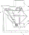
Fig. 1 is a schematic perspective view of a first embodiment of the present invention.
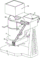
Fig. 2 is a schematic perspective view of a second embodiment of the present invention.
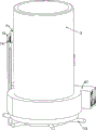
Fig. 3 is a partial perspective view of the present invention.
Fig. 4 is a schematic perspective view of the crushing mechanism of the present invention.
Fig. 5 is a schematic perspective view of the resonance blanking mechanism of the present invention.
Fig. 6 is a schematic perspective view of the double-sided air outlet mechanism of the present invention.
Fig. 7 is a schematic diagram of a first partially separated body structure of the intermittent blanking mechanism of the invention.
Fig. 8 is a schematic diagram of a second partial body structure of the intermittent blanking mechanism of the invention.
Fig. 9 is a schematic diagram of a partially-disassembled three-dimensional structure of the intermittent blanking mechanism.
Fig. 10 is a schematic perspective view of the pushing mechanism and the separating mechanism according to the present invention.
Wherein the figures include the following reference numerals: 1. stair frame, 2, special-shaped blanking frame, 3, slotted air duct, 4, crushing mechanism, 41, L-shaped motor frame, 42, bidirectional motor, 43, rotating shaft, 44, crushing roller, 45, gear I, 5, resonance blanking mechanism, 51, round head support frame, 52, transmission shaft, 53, cam, 54, disc, 55, connecting rod, 56, special-shaped belt rod sliding frame, 57, reset spring, 6, double-sided air outlet mechanism, 61, double-ended air inlet frame, 62, fan cover, 63, rotating impeller, 64, belt pulley with shaft, 65, transmission belt, 7, intermittent blanking mechanism, 71, special-shaped fixed frame, 72, L-shaped slotted swinging rod, 73, deflector rod rotating disc, 74, first torsion spring, 75, second spring, 8, forward pushing mechanism, 81, L-shaped rotating shaft frame, 82, short shaft, 83, gear II, 84, gear III, 85, circular ring slotted frame, 86, U-shaped rack, 87. the device comprises a sliding rack frame, 9 a separating mechanism, 91 a special-shaped slotted frame, 92 a round-head perforated net, 10 a dust removal filter screen.
Detailed Description
The technical solutions in the embodiments of the present invention will be clearly and completely described below with reference to the drawings in the embodiments of the present invention, and it is obvious that the described embodiments are only a part of the embodiments of the present invention, and not all of the embodiments. All other embodiments, which can be derived by a person skilled in the art from the embodiments given herein without making any creative effort, shall fall within the protection scope of the present invention.
Example 1
A processing device for recycling renewable resources based on environmental protection is disclosed, as shown in FIGS. 1-5, and comprises a stair frame 1, a special-shaped blanking frame 2, a slotted air pipe 3, a crushing mechanism 4 and a resonance blanking mechanism 5, wherein the special-shaped blanking frame 2 is fixedly connected to the upper portion of the stair frame 1, the slotted air pipe 3 is arranged at the lower portion of the special-shaped blanking frame 2, the crushing mechanism 4 is arranged at the upper portion of the special-shaped blanking frame 2, the resonance blanking mechanism 5 is fixedly connected to the special-shaped blanking frame 2, and the resonance blanking mechanism 5 is connected with the crushing mechanism 4.
The crushing mechanism 4 comprises an L-shaped motor frame 41, a bidirectional motor 42, a rotating shaft 43, a crushing roller 44 and a first gear 45, the L-shaped motor frame 41 is fixedly connected to the upper portion of the rear side of the special-shaped blanking frame 2, the bidirectional motor 42 is arranged on the upper portion of the L-shaped motor frame 41, the rotating shaft 43 is rotatably arranged on the left side and the right side of the upper portion of the special-shaped blanking frame 2, an output shaft on the front side of the bidirectional motor 42 is fixedly connected with the rear end of the left rotating shaft 43, the crushing roller 44 is fixedly connected to the rotating shaft 43, the crushing rollers 44 on the left side and the right side are located in the special-shaped blanking frame 2, the first gear 45 is fixedly connected to the front end of the rotating shaft 43, and the first gears 45 on the left side and the right side are meshed with each other. The resonance blanking mechanism 5 comprises a round head support frame 51, a transmission shaft 52, a cam 53, a disc 54, a connecting rod 55, a special-shaped strip rod sliding frame 56 and a return spring 57, the round head support frame 51 is fixedly connected to the upper portion of the right side of the special-shaped blanking frame 2, the right portion of the round head support frame 51 is rotatably connected to the transmission shaft 52, the cam 53 is installed at the rear portion of the transmission shaft 52, the disc 54 is fixedly connected to the rear side of the cam 53, the disc 54 is also installed on the rear side of a rotating shaft 43 on the right side, the connecting rod 55 is rotatably connected between the discs 54 on the left side and the right side, the special-shaped strip rod sliding frame 56 is slidably arranged on the lower portion of the special-shaped blanking frame 2, the special-shaped strip rod sliding frame 56 is located on the lower side of the cam 53, the special-shaped strip rod sliding frame 56 is in contact with the cam 53, and the return spring 57 is connected between the special-shaped strip rod sliding frame 56 and the special-shaped blanking frame 2.
When equipment starts, the staff climbs stair frame 1, put into heterotypic blanking frame 2 with the cable conductor, make cable conductor and crushing roller 44 contact, start two-way motor 42 and make left crushing roller 44 and left gear 45 anticlockwise rotation through left rotation axis 43, right side gear 45 clockwise thereupon, right side gear 45 clockwise turning makes right side crushing roller 44 clockwise turning through right side rotation axis 43, when the crushing roller 44 simultaneous operation of the left and right sides, with the cable conductor breakage, and then broken cable conductor can fall through heterotypic blanking frame 2 on the heterotypic pole carriage 56 of taking, heterotypic pole carriage 56 of taking can block broken cable conductor and prevent that it from continuing the landing.
The rotating shaft 43 on the right side rotates clockwise to enable the disc 54 on the left side to rotate clockwise, the disc 54 on the left side rotates clockwise to enable the disc 54 on the right side to rotate clockwise through the connecting rod 55, the disc 54 on the right side rotates clockwise to drive the cam 53 to rotate clockwise, the cam 53 rotates clockwise to extrude the special-shaped strip rod sliding frame 56 to move downwards, and broken cables fall into the slotted air duct 3 through the special-shaped strip rod sliding frame 56.
Example 2
On the basis of embodiment 1, as shown in fig. 6, the air conditioner further comprises a double-sided air outlet mechanism 6, the double-sided air outlet mechanism 6 is disposed below the slotted air duct 3, the double-sided air outlet mechanism 6 comprises a double-headed air inlet frame 61, a fan cover 62, a rotary impeller 63, belt shaft belt pulleys 64 and a transmission belt 65, the double-headed air inlet frame 61 is fixedly connected to the lower portion of the slotted air duct 3, the fan cover 62 is disposed on each of the front and rear sides of the left portion of the double-headed air inlet frame 61, the rotary impellers 63 are rotatably connected to the front and rear sides of the left portion of the double-headed air inlet frame 61, the rotary impellers 63 on the front and rear sides are respectively disposed in the fan covers 62 on the front and rear sides, an output shaft at the rear side of the bidirectional motor 42 is connected to the belt pulleys 64, the belt pulleys 64 are also mounted on the front side of the first gear 45 on the left side, and the transmission belt 65 is drivingly connected between the rotary impellers 63 and the belt pulleys 64 on the same side.
When the first gear 45 on the left side rotates clockwise to drive the belt pulley 64 on the front side to rotate clockwise through the transmission belt 65 on the front side, the bidirectional motor 42 can drive the belt pulley 64 on the rear side to rotate clockwise, the belt pulley 64 on the rear side drives the belt pulley 64 on the rear side to rotate clockwise through the transmission belt 65 on the rear side, the belt pulley 64 on the rear side rotates clockwise to drive the rotary impeller 63 to rotate clockwise, the rotary impeller 63 rotates clockwise to draw outside air into the double-head air inlet frame 61, the drawn air flows upwards in the slotted air duct 3 to be discharged, because in a broken cable, the weight of an insulator material and the weight of a copper wire material are different by four times, when the rotary impeller 63 rotates clockwise, the broken insulator material is blown upwards by the air drawn into the double-head air inlet frame 61 because of lighter weight, and the insulator material is separated from the copper wire material.
Example 3
On the basis of the embodiment 2, as shown in fig. 7-9, the device further includes an intermittent blanking mechanism 7, the intermittent blanking mechanism 7 is fixedly connected to one side of the slotted air duct 3, the intermittent blanking mechanism 7 includes a special-shaped fixing frame 71, an L-shaped slotted swing rod 72, a shift lever turntable 73, a first torsion spring 74 and a second torsion spring 75, the special-shaped fixing frame 71 is fixedly connected to the right portion of the front side of the special-shaped blanking frame 2, the lower portion of the right side of the special-shaped fixing frame 71 is rotatably connected with the L-shaped slotted swing rod 72, the L-shaped slotted swing rod 72 is in contact with the special-shaped strip rod sliding frame 56, the lower portion of the double-head air inlet frame 61 is rotatably connected with the shift lever turntable 73, the shift lever turntable 73 is in contact with the lower side of the L-shaped slotted swing rod 72, the first torsion spring 74 is connected between the L-shaped slotted swing rod 72 and the special-shaped fixing frame 71, and the second torsion spring 75 is connected between the shift lever turntable 73 and the double-head air inlet frame 61.
When the special-shaped strip rod sliding frame 56 moves downwards, the special-shaped strip rod sliding frame 56 pushes the left part of the L-shaped slotted swing rod 72 to swing downwards, the first torsion spring 74 is screwed therewith, the right part of the L-shaped slotted swing rod 72 swings rightwards to push the deflector rod rotary disc 73 to rotate, the second torsion spring 75 is screwed therewith, at the moment, the deflector rod rotary disc 73 no longer blocks the bottom of the slotted air pipe 3, so that copper wire materials in the slotted air pipe 3 fall into other collecting equipment on the stair frame 1, when the special-shaped strip rod sliding frame 56 resets, the L-shaped slotted swing rod 72 resets under the action of the first torsion spring 74, and the deflector rod rotary disc 73 resets under the action of the second torsion spring 75.
Example 4
On the basis of embodiment 3, as shown in fig. 10, the air duct system further comprises a separating mechanism 9, the separating mechanism 9 is fixedly connected to the front side of the special-shaped blanking frame 2, the separating mechanism 9 comprises a special-shaped slotted frame 91 and a round-head perforated net 92, the special-shaped slotted frame 91 is fixedly connected to the upper portion of the front side of the special-shaped blanking frame 2 on the lower side of the first gear 45, the round-head perforated net 92 is slidably arranged on the right side of the rear portion of the special-shaped slotted frame 91, and the round-head perforated net 92 is slidably matched with the slotted air duct 3.
Still including dust removal filter screen 10, the right side upper portion of heterotypic blanking frame 2 is connected with and holds the frame, and the frame that holds on heterotypic blanking frame 2 right side is equipped with at least three dust removal filter screen 10 in.
The dust removing filter screen is characterized by further comprising a front pushing mechanism 8, the front pushing mechanism 8 is arranged on the front side of the dust removing filter screen 10, the front pushing mechanism 8 comprises an L-shaped rotating shaft frame 81, a short shaft 82, a second gear 83, a third gear 84, a circular ring slotted frame 85, a U-shaped rack frame 86 and a sliding rack frame 87, the front side of a containing frame on the right side of the special-shaped blanking frame 2 is connected with the L-shaped rotating shaft frame 81, the lower portion of the L-shaped rotating shaft frame 81 is rotatably connected with the short shaft 82, the rear end of the short shaft 82 is provided with the second gear 83, the front end of the short shaft 82 is provided with the third gear 84, the upper portion of the slotted air pipe 3 is provided with the circular ring slotted frame 85, the circular ring slotted frame 85 is slidably provided with the U-shaped rack frame 86, the U-shaped rack frame 86 is meshed with the third gear 84, the lower portion of the rear side of the U-shaped rack frame 86 is provided with a convex block, the convex block on the lower portion of the rear side of the U-shaped rack frame 86 is in limit fit with the L-shaped slotted swing rod 72, the front side of the round head perforated net 92 is provided with the sliding rack frame 87, the sliding rack 87 is positioned on the right side of the special-shaped slotted rack 91, and the sliding rack 87 is meshed with the second gear 83.
The air pumped into the slotted air pipe 3 blows up the broken insulator materials, the broken insulator materials blown up upwards are tightly attached to the round-head perforated net 92, the air pumped into the slotted air pipe 3 flows upwards and enters the dust removal filter screen 10 through the round-head perforated net 92, and fine impurity dust in the air blown upwards is filtered through the dust removal filter screen 10, so that the dust removal effect is achieved; when the right part of the L-shaped slotted oscillating bar 72 swings rightwards to enable the U-shaped rack 86 to move upwards, the U-shaped rack 86 moves upwards to drive the gear three 84 to rotate anticlockwise, the gear three 84 rotates anticlockwise to drive the gear two 83 to rotate anticlockwise through the short shaft 82, the gear two 83 rotates anticlockwise to drive the sliding rack 87 to move rightwards, the sliding rack 87 moves rightwards to enable the round-head perforated net 92 to move rightwards, the right side of the round-head perforated net 92 is not contacted with the slotted air duct 3 any more, at the moment, the left part of the round-head perforated net 92 shields the upper side of the slotted air duct 3, and therefore, insulator materials in the slotted air duct 3 are prevented from being blown upwards, while the insulator material in the right side of the round-headed open mesh 92 then falls down outside the device to be collected by other devices, when the L-shaped slotted swing link 72 is reset, the L-shaped slotted swing link 72 drives the U-shaped rack 86 to reset, so that the round-head perforated net 92 moves leftwards to reset.
Although embodiments of the present invention have been shown and described, it will be appreciated by those skilled in the art that changes, modifications, substitutions and alterations can be made in these embodiments without departing from the principles and spirit of the invention, the scope of which is defined in the appended claims and their equivalents.
Claims (5)
1. A treatment device for recycling renewable resources based on environmental protection is characterized by comprising a stair frame (1), a special-shaped blanking frame (2) for conveying crushed cables, a slotted air pipe (3), a crushing mechanism (4) positioned in the special-shaped blanking frame (2) and a resonance blanking mechanism (5) for enabling the crushed cables to fall;
the device comprises a stair frame (1), wherein the upper part of the stair frame (1) is fixedly connected with a special blanking frame (2) for conveying a cable for crushing treatment;
the slotted air pipe (3), the slotted air pipe (3) is fixedly connected to the lower part of the special-shaped blanking frame (2);
the crushing mechanism (4) is used for crushing the waste cable, and the crushing mechanism (4) is fixedly connected to the upper part of the special-shaped blanking frame (2);
the special-shaped blanking frame (2) is fixedly connected with a resonance blanking mechanism (5) used for enabling the crushed cable to fall, and the resonance blanking mechanism (5) is connected with the crushing mechanism (4);
the double-sided air outlet device is characterized by further comprising a double-sided air outlet mechanism (6), wherein the double-sided air outlet mechanism (6) is arranged below the slotted air pipe (3), the double-sided air outlet mechanism (6) comprises a double-end air inlet frame (61), a fan cover (62), a rotary impeller (63), a belt pulley (64) with a shaft and a transmission belt (65), the double-end air inlet frame (61) is fixedly connected to the lower portion of the slotted air pipe (3), the fan cover (62) is arranged on each of two sides of the double-end air inlet frame (61), the rotary impellers (63) are rotatably connected to each of two sides of the double-end air inlet frame (61), the rotary impellers (63) on each of two sides are respectively located in the fan covers (62) on each of two sides, the belt pulley (64) with the shaft is connected to each of two sides of the crushing mechanism (4), and the transmission belt (65) is connected between the rotary impellers (63) with the belt pulley (64) with the same side;
the special-shaped blanking device is characterized by further comprising a separating mechanism (9), wherein the separating mechanism (9) is fixedly connected to the front side of the special-shaped blanking frame (2), the separating mechanism (9) comprises a special-shaped slotted frame (91) and a round-head hole opening net (92), the special-shaped slotted frame (91) is fixedly connected to the upper portion of the front side of the special-shaped blanking frame (2), the round-head hole opening net (92) is movably arranged on the rear side of the special-shaped slotted frame (91), and the round-head hole opening net (92) is in sliding fit with the slotted air pipe (3);
the special-shaped blanking device is characterized by further comprising a dust removing filter screen (10), the upper portion of the right side of the special-shaped blanking frame (2) is connected with a containing frame, and a plurality of dust removing filter screens (10) are arranged in the containing frame on the right side of the special-shaped blanking frame (2).
2. The processing equipment for recycling renewable resources based on environmental protection as recited in claim 1, wherein the crushing mechanism (4) comprises an L-shaped motor frame (41), a two-way motor (42), a rotating shaft (43), a crushing roller (44) and a first gear (45), the L-shaped motor frame (41) is fixedly connected to the upper portion of the rear side of the special-shaped blanking frame (2), the two-way motor (42) is arranged on the L-shaped motor frame (41), the two rotating shafts (43) are rotatably arranged on the upper portion of the special-shaped blanking frame (2), the two rotating shafts (43) are arranged in a bilateral symmetry manner, the output shaft of the front side of the two-way motor (42) is fixedly connected to the rotating shaft (43) at the left side, the crushing roller (44) is fixedly connected to the rotating shaft (43) at the inner side of the special-shaped blanking frame (2), the first gear (45) is fixedly connected to the rotating shaft (43) at the front side of the special-shaped blanking frame (2), and the two first gears (45) are meshed with each other, the belt shaft belt wheels (64) on the two sides are respectively connected with the output shaft on the rear side of the bidirectional motor (42) and the front side of the gear I (45) on the left side.
3. The processing equipment for recycling renewable resources based on environmental protection as recited in claim 2, wherein the resonance blanking mechanism (5) comprises a round-head support frame (51), a transmission shaft (52), a cam (53), a disc (54), a connecting rod (55), a special-shaped strip rod sliding frame (56) and a return spring (57), the round-head support frame (51) is fixedly connected to the upper portion of the right side of the special-shaped blanking frame (2), the right portion of the round-head support frame (51) is rotatably connected to the transmission shaft (52), the cam (53) is installed at the rear portion of the transmission shaft (52), the disc (54) is fixedly connected to the cam (53), the disc (54) is also installed at the rear side of the rotating shaft (43) at the right side, the connecting rod (55) is rotatably connected between the two discs (54), the special-shaped strip rod sliding frame (56) is slidably installed at the lower portion of the special-shaped blanking frame (2), and the special-shaped strip rod sliding frame (56) is in contact with the cam (53), a return spring (57) is connected between the special-shaped strip rod sliding frame (56) and the special-shaped blanking frame (2).
4. The treatment equipment for recycling the renewable resources based on the environmental protection as recited in claim 3, characterized in that it further comprises an intermittent blanking mechanism (7), the intermittent blanking mechanism (7) is fixedly connected to one side of the slotted air duct (3), the intermittent blanking mechanism (7) comprises a special-shaped fixing frame (71), an L-shaped slotted swing rod (72), a deflector rod turntable (73), a first torsion spring (74) and a second torsion spring (75), the special-shaped fixing frame (71) is fixedly connected to the front side of the special-shaped blanking frame (2), the lower part of the special-shaped fixing frame (71) is rotatably connected with the L-shaped slotted swing rod (72), the L-shaped slotted swing rod (72) is in contact with the special-shaped strip rod sliding frame (56), the lower part of the double-head air intake frame (61) is rotatably connected with the deflector rod turntable (73), the deflector rod turntable (73) is in contact with the lower side of the L-shaped slotted swing rod (72), the first torsion spring (74) is connected between the L-shaped slotted swing rod (72) and the special-shaped fixing frame (71), a second torsion spring (75) is connected between the deflector rod rotary disc (73) and the double-head air inlet frame (61).
5. The treatment equipment for recycling renewable resources based on environmental protection as recited in claim 4, characterized by further comprising a forward pushing mechanism (8), wherein the forward pushing mechanism (8) is arranged at the front side of the dust removing filter screen (10), the forward pushing mechanism (8) comprises an L-shaped rotating shaft frame (81), a short shaft (82), a second gear (83), a third gear (84), a circular ring slotting frame (85), a U-shaped rack frame (86) and a sliding rack frame (87), the front side of the containing frame at the right side of the special-shaped blanking frame (2) is connected with the L-shaped rotating shaft frame (81), the lower part of the L-shaped rotating shaft frame (81) is rotatably connected with the short shaft (82), the rear side of the short shaft (82) is provided with the second gear (83), the front side of the short shaft (82) is provided with the third gear (84), the upper part of the slotting air duct (3) is provided with the circular ring slotting frame (85), the circular ring slotting frame (86) is slidably arranged on the circular ring slotting frame (85), the U-shaped rack (86) is meshed with the third gear (84), the U-shaped rack (86) is in limit fit with the L-shaped slotted swing rod (72), the sliding rack (87) is arranged on the front side of the round-head perforated net (92), and the sliding rack (87) is meshed with the second gear (83).
Priority Applications (1)
| Application Number | Priority Date | Filing Date | Title |
|---|---|---|---|
| CN202110864278.3A CN113304813B (en) | 2021-07-29 | 2021-07-29 | Processing equipment for recycling renewable resources based on environmental protection |
Applications Claiming Priority (1)
| Application Number | Priority Date | Filing Date | Title |
|---|---|---|---|
| CN202110864278.3A CN113304813B (en) | 2021-07-29 | 2021-07-29 | Processing equipment for recycling renewable resources based on environmental protection |
Publications (2)
| Publication Number | Publication Date |
|---|---|
| CN113304813A true CN113304813A (en) | 2021-08-27 |
| CN113304813B CN113304813B (en) | 2021-10-19 |
Family
ID=77382064
Family Applications (1)
| Application Number | Title | Priority Date | Filing Date |
|---|---|---|---|
| CN202110864278.3A Active CN113304813B (en) | 2021-07-29 | 2021-07-29 | Processing equipment for recycling renewable resources based on environmental protection |
Country Status (1)
| Country | Link |
|---|---|
| CN (1) | CN113304813B (en) |
Citations (11)
| Publication number | Priority date | Publication date | Assignee | Title |
|---|---|---|---|---|
| KR20100010835U (en) * | 2009-04-27 | 2010-11-04 | 한스엔지니어링주식회사 | Apparatus For Recycling Waste Electric Wire |
| CN205122304U (en) * | 2015-11-26 | 2016-03-30 | 台州奇艺环保设备科技有限公司 | Large -scale old and useless cable of dry -type is disassembled separation and is retrieved production line |
| KR20170106873A (en) * | 2016-03-14 | 2017-09-22 | 주식회사 상해메탈 | Apparatus and method for separating copper from ground waste electric wire |
| CN108022700A (en) * | 2018-01-09 | 2018-05-11 | 成都菲斯普科技有限公司 | A kind of discarded electric power cable cuts through recycling machine |
| CN108335808A (en) * | 2018-01-09 | 2018-07-27 | 成都菲斯普科技有限公司 | A kind of crushing retracting device of scrap electrical wires cable |
| CN110575960A (en) * | 2019-08-14 | 2019-12-17 | 张美华 | A waste wire recycling device |
| CN111790476A (en) * | 2020-07-06 | 2020-10-20 | 宛兴友 | Sludge regeneration resource utilization integrated treatment system |
| CN211755399U (en) * | 2019-12-24 | 2020-10-27 | 武汉正丰汽车零部件系统有限责任公司 | Automobile parts processing garbage collection device |
| CN112271041A (en) * | 2020-09-21 | 2021-01-26 | 温家深 | Broken copper of cable moulds separator |
| CN212943331U (en) * | 2020-08-13 | 2021-04-13 | 灌南县福田五棵树食用菌有限公司 | Timber rubbing crusher is used in domestic fungus cultivation |
| CN213166344U (en) * | 2020-04-27 | 2021-05-11 | 上海塑创源环保科技有限公司 | Plastic refuse reducing mechanism for environmental protection |
-
2021
- 2021-07-29 CN CN202110864278.3A patent/CN113304813B/en active Active
Patent Citations (11)
| Publication number | Priority date | Publication date | Assignee | Title |
|---|---|---|---|---|
| KR20100010835U (en) * | 2009-04-27 | 2010-11-04 | 한스엔지니어링주식회사 | Apparatus For Recycling Waste Electric Wire |
| CN205122304U (en) * | 2015-11-26 | 2016-03-30 | 台州奇艺环保设备科技有限公司 | Large -scale old and useless cable of dry -type is disassembled separation and is retrieved production line |
| KR20170106873A (en) * | 2016-03-14 | 2017-09-22 | 주식회사 상해메탈 | Apparatus and method for separating copper from ground waste electric wire |
| CN108022700A (en) * | 2018-01-09 | 2018-05-11 | 成都菲斯普科技有限公司 | A kind of discarded electric power cable cuts through recycling machine |
| CN108335808A (en) * | 2018-01-09 | 2018-07-27 | 成都菲斯普科技有限公司 | A kind of crushing retracting device of scrap electrical wires cable |
| CN110575960A (en) * | 2019-08-14 | 2019-12-17 | 张美华 | A waste wire recycling device |
| CN211755399U (en) * | 2019-12-24 | 2020-10-27 | 武汉正丰汽车零部件系统有限责任公司 | Automobile parts processing garbage collection device |
| CN213166344U (en) * | 2020-04-27 | 2021-05-11 | 上海塑创源环保科技有限公司 | Plastic refuse reducing mechanism for environmental protection |
| CN111790476A (en) * | 2020-07-06 | 2020-10-20 | 宛兴友 | Sludge regeneration resource utilization integrated treatment system |
| CN212943331U (en) * | 2020-08-13 | 2021-04-13 | 灌南县福田五棵树食用菌有限公司 | Timber rubbing crusher is used in domestic fungus cultivation |
| CN112271041A (en) * | 2020-09-21 | 2021-01-26 | 温家深 | Broken copper of cable moulds separator |
Also Published As
| Publication number | Publication date |
|---|---|
| CN113304813B (en) | 2021-10-19 |
Similar Documents
| Publication | Publication Date | Title |
|---|---|---|
| CN111822362A (en) | Screening device for waste plastic bottles and glass bottles | |
| CN113304813B (en) | Processing equipment for recycling renewable resources based on environmental protection | |
| CN211726560U (en) | A kind of grain mechanical impurity removal device | |
| CN114558655B (en) | Waste material treatment device with metal recovery effect | |
| CN212468761U (en) | Graphite powder is collected and is used edulcoration device | |
| CN114378090A (en) | Battery recycling equipment of new energy automobile | |
| CN117358367B (en) | Gangue solid waste treatment equipment | |
| CN112657890A (en) | Time-saving and labor-saving sun shield production line | |
| CN221245326U (en) | Dust collector is retrieved to old and useless circuit board | |
| CN218743847U (en) | Waste recovery device | |
| CN217700620U (en) | Solid waste treatment crushing device | |
| CN216395757U (en) | Multifunctional module formula dust remover | |
| CN116651747A (en) | A light material air separation device for sorting and sorting construction waste | |
| CN212493156U (en) | Broken recovery unit of abandonment building materials for interior architecture | |
| CN211726918U (en) | Broken recovery unit of substandard product circuit board | |
| CN221890115U (en) | A magnetic separation treatment device for urban construction waste | |
| CN112317044A (en) | A construction environmental protection waste screening and separation device | |
| CN217664553U (en) | Industrial dust collector capable of collecting and recycling metal particles | |
| CN222511106U (en) | Slag iron sieving mechanism | |
| CN222112592U (en) | A new type of recycling device for mixed cashmere | |
| CN218573911U (en) | Auxiliary iron removing equipment for cement mill | |
| CN223946132U (en) | Silica slag classifying and screening device | |
| CN222472733U (en) | Automatic waste cleaning device | |
| CN205943606U (en) | Powerful breaker of cable | |
| CN214516663U (en) | Can avoid piece processing apparatus of cnc engraving and milling machine of raise dust |
Legal Events
| Date | Code | Title | Description |
|---|---|---|---|
| PB01 | Publication | ||
| PB01 | Publication | ||
| SE01 | Entry into force of request for substantive examination | ||
| SE01 | Entry into force of request for substantive examination | ||
| GR01 | Patent grant | ||
| GR01 | Patent grant |