Sewage treatment device convenient for intercepting and degrading pollutants in sewage
Technical Field
The invention relates to the technical field related to sewage treatment, in particular to a sewage treatment device convenient for intercepting and degrading pollutants in sewage.
Background
Along with the industry, the rapid development of agricultural, people's standard of living is also constantly improving, wherein domestic sewage and municipal sewage are also increasing gradually, the sewage that does not handle directly discharges in rivers, lakes and seas, not only can the polluted environment, also lead to the great decline of natural water resource purity rate, therefore need utilize sewage treatment plant to purify sewage before discharging sewage, can improve municipal sewage's reuse rate after the sewage purification, prevent sewage to the large tracts of land pollution of water, at present, sewage treatment plant's on the market style and function are more and more diversified.
The sewage treatment device convenient for intercepting and degrading pollutants in sewage at present has the following defects in the using process, mainly as follows:
1. the interception and degradation of pollutants in the sewage are inconvenient, so that garbage is mixed in the sewage when the sewage is explained;
2. water and sludge are not easily isolated, so that when the treated water body is discharged, the sludge can be mixed into the water body;
3. the garbage is easy to contain sewage, so that the sewage is remained in the garbage, and the sewage is not fully treated;
4. inconvenient filterable speed of accelerating, easy jam leads to rubbish to be long-pending to stay on the filter and makes sewage get into the inside speed of box lower extreme slow, and rubbish is stifled in the hole of filter easily, consequently, we provide one kind and be convenient for to the sewage treatment plant that pollutant was held back and is degraded in the sewage to in solving the problem that proposes in the aforesaid.
Disclosure of Invention
The invention aims to provide a sewage treatment device convenient for intercepting and degrading pollutants in sewage, and aims to solve the problems that most of sewage treatment devices in the background art are inconvenient for intercepting and degrading the pollutants in the sewage, are not easy to isolate water and sludge, easily contain sewage in garbage, are inconvenient for accelerating the filtering speed and are easy to block.
In order to achieve the purpose, the invention provides the following technical scheme: a sewage treatment device convenient for intercepting and degrading pollutants in sewage comprises a box body, a first motor, a second motor and a third motor, wherein the left upper end inside the box body is connected with a baffle in a welding mode, the middle end of the baffle is connected with a crushing toothed roller in a rotating mode, the right end of the crushing toothed roller is fixedly connected with a gear, the right end of the gear is provided with the first motor, the left upper end inside the box body is provided with a vibration mechanism, the right end of the vibration mechanism is provided with the second motor, the middle upper end inside the box body is connected with a filter plate in a bolt mode, the middle upper end in the right wall of the box body is connected with a discharge hole in a welding mode, and the inside of the discharge hole is connected with a sealing plug in a clamping mode;
lower extreme welded connection has the loading board in the inside of box, and the well upper end of loading board rotates and is connected with first connecting axle to the surface welded connection of first connecting axle has the stirring leaf, the well middle and upper end fixedly connected with first awl tooth of first connecting axle, and the left end of first awl tooth contacts with second awl tooth, the left end fixedly connected with second connecting axle of second awl tooth, and the left end integration of second connecting axle is connected with the second connecting piece, the third motor is installed to the left end of second connecting piece, and installs the belt on the second connecting piece, the wall homogeneous integration of both sides is connected with the guide board around the box upper end.
Preferably, the upper end rotates in the inside of box and is connected with the threaded rod, and the threaded connection of threaded rod is inside the rear end of push pedal to the inside through connection of front end of push pedal has the gag lever post, and the left end integration of threaded rod is connected with first connecting piece moreover.
Preferably, the crushing fluted roller is arranged symmetrically in front and back of the longitudinal central axis of the box body, the crushing fluted roller monomers are arranged in a staggered mode, and the gear monomers are connected in a meshing mode.
Preferably, the push pedal passes through the gag lever post and constitutes sliding structure with the threaded rod, and the longitudinal section shape of the first connecting piece that second connecting piece and threaded rod right-hand member are connected is "worker" style of calligraphy to the second connecting piece passes through the belt and constitutes transmission structure with first connecting piece.
Preferably, the vibrations mechanism includes spacing seat, regulation pole, regulating block, vibrations board, connecting strip and pivot, and the pivot is installed to the right-hand member of second motor, and the right-hand member fixedly connected with connecting strip of pivot, connecting strip upper end and regulating block contact, and the regulating block integration is connected in the well upper end of adjusting the pole, and the bottom welded connection of adjusting the pole has the vibrations board, adjusts pole through connection in spacing seat, and spacing welded connection is on the left side wall of box.
Preferably, the longitudinal section shape of connecting strip is "S" style of calligraphy, and adjusts the pole and pass through connecting strip and filter constitution elevation structure to the bottom of vibrations board and filter all are the slope form setting.
Preferably, the downside of loading board is provided with the connecting plate, and the inside fixedly connected with third connecting axle of the outer end of connecting plate to the lower extreme in the inside of box is connected in the rotation of third connecting axle.
Preferably, the second connecting shaft, the second conical tooth, the first conical tooth and the first connecting shaft sequentially form a linkage structure, the stirring blades are arranged at equal angles relative to the center of the first connecting shaft, the cross section of the bearing plate is shaped like a Chinese character 'zhong', and the diameter of the rotating track of the stirring blades is smaller than the width of the box body.
Preferably, the right end of the third connecting shaft is fixedly connected with a worm wheel, and the lower end of the worm wheel is in contact with the bidirectional worm.
Preferably, the connecting plates are symmetrically arranged in front and back of a longitudinal central axis of the box body, the bidirectional worm, the third connecting shaft and the connecting plates sequentially form a linkage structure, the rotating directions of the single connecting plates are opposite, and the sum of the areas of the single connecting plates is equal to the area of the inner end of the box body.
Compared with the prior art, the invention has the beneficial effects that: the sewage treatment device convenient for intercepting and degrading the pollutants in the sewage is convenient for intercepting and degrading the pollutants in the sewage, is easy to isolate water and sludge, prevents the garbage from containing the sewage, is convenient for accelerating the filtering speed and preventing blockage;
1. the sewage treatment device is provided with a filter plate, a push plate and a stirring blade, the filter plate is arranged, the filter plate is used for filtering garbage in sewage, the push plate and a threaded rod are structurally designed, the threaded rod is enabled to limit the push plate when rotating, the push plate is enabled to slide in a box body through the threaded rod, the garbage on the filter plate is pushed into a discharge port, the second connecting shaft and the first connecting shaft are structurally designed, the second conical tooth is meshed with the first conical tooth to drive the first connecting shaft to rotate, the diameter of the rotating track of the stirring blade is smaller than the width size of the box body, the first connecting shaft drives the stirring blade to rotate in the box body, sewage and sewage treatment agent are mixed, and therefore the interception and degradation of pollutants in the sewage are facilitated;
2. the bidirectional worm is structurally designed with the connecting plate, so that the bidirectional worm is meshed with the connecting plate to drive the third connecting shaft to rotate when rotating, the rotating directions of the connecting plate monomers are opposite through the arrangement of the bidirectional worm, the third connecting shaft drives the connecting plate to rotate, the sum of the areas of the connecting plate monomers is equal to the area of the inner end of the box body, and water and sludge in the box body are isolated when the connecting plate is in a parallel state;
3. the garbage crusher is provided with crushing toothed rollers and gears, the gear monomers are meshed and connected, so that the rotation directions of the crushing toothed roller monomers are opposite, the crushing toothed roller monomers are arranged in a staggered mode, the crushing toothed roller monomers rotate to crush garbage in sewage, and the garbage is left on a filter plate, so that the garbage is prevented from containing sewage;
4. be equipped with the connecting strip, adjust pole and vibrations board, adjust the structural design of pole and filter for the connecting strip drives the regulating block when rotating and reciprocates, lets adjust the pole and goes up and down in spacing seat, and the bottom and the filter of vibrations board all are slope form setting, and it collides the filter to make to let the vibrations board when adjusting the pole and go up and down, thereby conveniently accelerates filterable speed, prevents to block up.
Drawings
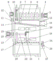
FIG. 1 is a schematic front sectional view of the present invention;
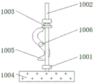
FIG. 2 is a schematic structural diagram of a vibration mechanism according to the present invention;
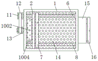
FIG. 3 is a schematic view of a top-view cross-sectional structure of the connection between the stop lever and the push plate according to the present invention;
FIG. 4 is a schematic sectional view of the crushing roller gear and the gear assembly in plan view;
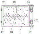
FIG. 5 is a right side sectional view of the connection between the connection plate and the third connection shaft according to the present invention;
FIG. 6 is a schematic diagram of the right side view of the worm wheel and the bidirectional worm according to the present invention;
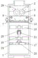
FIG. 7 is a right side view of the connecting bar and the adjusting bar according to the present invention;
FIG. 8 is a schematic top view of the connection between the carrier plate and the box according to the present invention;
FIG. 9 is a schematic left side sectional view of the first connecting member and the belt of the present invention.
In the figure: 1. a box body; 2. a baffle plate; 3. a crushing toothed roller; 4. a gear; 5. a first motor; 6. a threaded rod; 7. pushing the plate; 8. a limiting rod; 9. a second motor; 10. a vibration mechanism; 1001. a limiting seat; 1002. adjusting a rod; 1003. an adjusting block; 1004. a vibration plate; 1005. a connecting strip; 1006. a rotating shaft; 11. a first connecting member; 12. a belt; 13. a second connecting member; 14. a filter plate; 15. a discharge port; 16. a sealing plug; 17. a carrier plate; 18. a first connecting shaft; 19. stirring blades; 20. a first bevel gear; 21. a second taper tooth; 22. a second connecting shaft; 23. a third motor; 24. a third connecting shaft; 25. a connecting plate; 26. a worm gear; 27. a bidirectional worm; 28. a guide plate.
Detailed Description
The technical solutions in the embodiments of the present invention will be clearly and completely described below with reference to the drawings in the embodiments of the present invention, and it is obvious that the described embodiments are only a part of the embodiments of the present invention, and not all embodiments, and all other embodiments obtained by a person of ordinary skill in the art without creative efforts based on the embodiments of the present invention belong to the protection scope of the present invention.
Referring to fig. 1-9, the present invention provides a technical solution: a sewage treatment device convenient for intercepting and degrading pollutants in sewage comprises a box body 1, a baffle plate 2, a grinding toothed roller 3, a gear 4, a first motor 5, a threaded rod 6, a push plate 7, a limiting rod 8, a second motor 9, a vibration mechanism 10, a first connecting piece 11, a belt 12, a second connecting piece 13, a filter plate 14, a discharge hole 15, a sealing plug 16, a bearing plate 17, a first connecting shaft 18, a stirring blade 19, a first conical tooth 20, a second conical tooth 21, a second connecting shaft 22, a third motor 23, a third connecting shaft 24, a connecting plate 25, a worm wheel 26, a bidirectional worm 27 and a guide plate 28, wherein the baffle plate 2 is welded at the left upper end inside the box body 1, the grinding toothed roller 3 is rotatably connected at the middle end of the baffle plate 2, the gear 4 is fixedly connected at the right end of the grinding toothed roller 3, the first motor 5 is installed at the right end of the gear 4, the vibration mechanism 10 is arranged at the left upper end inside the box body 1, the right end of the vibration mechanism 10 is provided with a second motor 9, the middle upper end in the box body 1 is connected with a filter plate 14 through a bolt, the middle upper end in the right wall of the box body 1 is connected with a discharge hole 15 in a welding mode, and the interior of the discharge hole 15 is connected with a sealing plug 16 in a clamping mode;
lower extreme welded connection has loading board 17 in the inside of box 1, and the well upper end of loading board 17 rotates and is connected with first connecting axle 18, and the surface welded connection of first connecting axle 18 has stirring leaf 19, the well upper end fixedly connected with first awl tooth 20 of first connecting axle 18, and the left end of first awl tooth 20 contacts with second awl tooth 21, the left end fixedly connected with second connecting axle 22 of second awl tooth 21, and the left end integration of second connecting axle 22 is connected with second connecting piece 13, third motor 23 is installed to the left end of second connecting piece 13, and install belt 12 on the second connecting piece 13, the wall uniformity of both sides around the upper end of box 1 is connected with guide board 28.
As shown in fig. 1, 4 and 5, the crushing teeth rollers 3 are symmetrically arranged in front and back of the longitudinal central axis of the box body 1, the crushing teeth rollers 3 are arranged in a staggered manner, the single gears 4 are connected in a meshing manner, when the single gears 4 are meshed, the rotation directions of the crushing teeth rollers 3 are opposite, and garbage is crushed between the crushing teeth rollers 3;
as shown in fig. 1, 2 and 7, the vibration mechanism 10 includes a position-limiting seat 1001, an adjusting rod 1002, an adjusting block 1003, a vibration plate 1004, a connecting bar 1005 and a rotating shaft 1006, the right end of the second motor 9 is provided with the rotating shaft 1006, the right end of the rotating shaft 1006 is fixedly connected with the connecting bar 1005, the upper end of the connecting bar 1005 is in contact with the adjusting block 1003, the adjusting block 1003 is integrally connected with the middle upper end of the adjusting rod 1002, the bottom end of the adjusting rod 1002 is welded with the vibration plate 1004, the adjusting rod 1002 is connected in the position-limiting seat 1001 in a penetrating manner, the position-limiting seat is welded on the left side wall 1001 of the box body 1, the longitudinal section of the connecting bar 1005 is in an "S" shape, the adjusting rod 1002 forms a lifting structure with the filter plate 14 through the connecting bar 1005, the bottom end of the vibration plate 1004 and the filter plate 14 are both arranged in an inclined manner, the connecting bar 1005 can drive the adjusting block 1003 to lift when rotating, the adjusting block 1003 drives the adjusting rod 1002 to move up and down in the position-limiting seat 1001, the lower end of the vibration plate 1004 is fully contacted with the upper end of the filter plate 14, so that the connecting strips 1005 collide with the filter plate 14;
as shown in the figures 1, 5 and 6, a connecting plate 25 is arranged at the lower side of the bearing plate 17, a third connecting shaft 24 is fixedly connected inside the outer end of the connecting plate 25, the third connecting shaft 24 is rotatably connected at the middle and lower ends inside the box body 1, a worm wheel 26 is fixedly connected at the right end of the third connecting shaft 24, the lower end of the worm wheel 26 is contacted with a bidirectional worm 27, the connecting plates 25 are symmetrically arranged front and back about the longitudinal central axis of the box body 1, the bidirectional worm 27, the third connecting shaft 24 and the connecting plate 25 sequentially form a linkage structure, the rotating directions of the single connecting plates 25 are opposite, the sum of the areas of the single connecting plates 25 is equal to the area of the inner end of the box body 1, 2 groups of connecting plates 25 are arranged inside the middle and lower end of the box body 1, the bidirectional worm 27 is meshed with the worm wheel 26 to drive the third connecting shaft 24 to rotate when rotating, the third connecting shaft 24 drives the connecting plates 25 to turn over, so that the connecting plates 25 at the front and rear ends can simultaneously rotate to plug the lower end of the interior of the box body 1;
as shown in fig. 1 and 8, the second connecting shaft 22, the second conical tooth 21, the first conical tooth 20 and the first connecting shaft 18 sequentially form an interlocking structure, the stirring blade 19 is arranged at an equal angle relative to the center of the first connecting shaft 18, the cross section of the bearing plate 17 is in a shape of a Chinese character 'zhong', the diameter of the rotating track of the stirring blade 19 is smaller than the width of the box body 1, the second connecting shaft 22 drives the second conical tooth 21 to rotate when rotating, the second conical tooth 21 is meshed with the first conical tooth 20 to drive the first connecting shaft 18 to rotate, the stirring blade 19 is uniformly arranged on the outer surface of the first connecting shaft 18, the bearing plate 17 cannot prevent water from entering the inner lower end of the box body 1, the bearing plate 17 cannot influence the rotation of the connecting plate 25, and the stirring blade 19 cannot be contacted with the front and rear side walls of the box body 1 when rotating;
as shown in fig. 1, 3 and 9, a threaded rod 6 is rotatably connected to the upper end of the interior of the box body 1, and the thread of the threaded rod 6 is connected to the interior of the rear end of the push plate 7, a limit rod 8 is penetratingly connected inside the front end of the push plate 7, the left end of the threaded rod 6 is integrally connected with a first connecting piece 11, the push plate 7 and the threaded rod 6 form a sliding structure through the limit rod 8, the longitudinal section shapes of the second connecting piece 13 and the first connecting piece 11 connected with the right end of the threaded rod 6 are I-shaped, and second connecting piece 13 passes through belt 12 and first connecting piece 11 constitution transmission structure, and threaded rod 6 spacing through gag lever post 8 makes push pedal 7 remove about the inside of box 1 when rotating, prevents that belt 12 from breaking away from first connecting piece 11 and second connecting piece 13, drives first connecting piece 11 through belt 12 when second connecting piece 13 rotates.
The working principle is as follows: when the sewage treatment device convenient for intercepting and degrading pollutants in sewage is used, the sewage treatment agent is poured into the lower inner end of the box body 1 by combining the graph shown in the figure 1 and the graph shown in the figure 4, at the moment, the connecting plate 25 is in a horizontal state to block the lower inner end of the box body 1, sewage is poured into the box body 1 through the water inlet at the upper end of the box body 1, the sewage is guided onto the crushing toothed rollers 3 through the guide plate 28, the first motor 5 drives the gear 4 at the front end to rotate when working, the gear 4 at the front end is meshed with the gear 4 at the rear end to drive the crushing toothed rollers 3 to rotate, the rotating directions of the single crushing toothed rollers 3 are opposite, garbage in the sewage is crushed through the rotation between the single crushing toothed rollers 3, the crushed garbage falls on the filter plate 14 and is filtered through the filter plate 14, and therefore the garbage is prevented from containing sewage;
with reference to fig. 1, 2 and 7, the second motor 9 drives the rotating shaft 1006 to rotate when operating, the rotating shaft 1006 drives the S-shaped connecting bar 1005 to rotate when rotating, the connecting bar 1005 drives the adjusting block 1003 to lift, so that the adjusting block 1003 drives the adjusting rod 1002 to move up and down in the limiting seat 1001, and the vibrating plate 1004 collides with the filter plate 14 when lifting, thereby increasing the filtering speed of the filter plate 14, meanwhile, the ground garbage can move to the right end, and the holes of the filter plate 14 cannot be blocked by garbage to prevent blockage;
referring to fig. 1, 5 and 8, the filter plate 14 traps pollutants such as garbage in sewage through the filter plate 14, the sewage enters the upper end of the connecting plate 25 to be mixed with sewage treatment agent, the third motor 23 drives the second connecting shaft 22 to rotate when working, the second bevel gear 21 is meshed with the first bevel gear 20 to drive the first connecting shaft 18 to rotate, the stirring blade 19 arranged at equal angle is rotated to fully mix the sewage and the sewage treatment agent, the third motor 23 drives the second connecting piece 13 to rotate and drives the first connecting piece 11 to rotate through the belt 12 when driving the second connecting piece 13 to rotate, the first connecting piece 11 drives the threaded rod 6 to rotate, the push plate 7 is limited through the limiting rod 8, the push plate 7 is driven to move in the box body 1 when the threaded rod 6 rotates, the push plate 7 pushes the garbage on the filter plate 14 into the discharge hole 15, and the sealing plug 16 is separated from the discharge hole 15, the garbage in the filter plate 14 is taken out through the discharge hole 15, so that the interception and degradation of pollutants in the sewage are facilitated, and the forward and reverse rotation is conveniently adjusted by the third motor 23 with the model number of XD-60 KTYZ;
referring to fig. 1, 5 and 6, after the mixing of the sewage and the sewage treatment agent by the mixing blade 19, the third motor 23 stops working, the bidirectional worm 27 is rotated to be meshed with the worm wheel 26, the rotation directions of the third connecting shaft 24 single bodies are opposite through the arrangement of the bidirectional worm 27, so that the third connecting shaft 24 drives the connecting plate 25 to rotate to enable the connecting plate 25 to be in a vertical state, water in the box body 1 enters the lower end, degraded sewage is allowed to stand, so that the sludge is settled at the bottom end inside the box body 1, the flocculate floats at the lower end of the filter plate 14, the bidirectional worm 27 is rotated to be meshed with the worm wheel 26 to drive the third connecting shaft 24 to rotate, the connecting plates 25 rotate among the single bodies and are in a horizontal state to block the lower end inside the box body 1, therefore, the connection plates 25 are isolated from the sludge in the water body, and the working principle of the sewage treatment device is that pollutants in the sewage can be conveniently intercepted and degraded.
The standard parts used in the invention can be purchased from the market, the special-shaped parts can be customized according to the description of the specification and the accompanying drawings, the specific connection mode of each part adopts conventional means such as bolts, rivets, welding and the like mature in the prior art, the machinery, parts and equipment adopt conventional models in the prior art, and the circuit connection adopts the conventional connection mode in the prior art, and the details are not described, and the content not described in detail in the specification belongs to the prior art known by persons skilled in the art.
Although the present invention has been described in detail with reference to the foregoing embodiments, it will be apparent to those skilled in the art that various changes in the embodiments and/or modifications of the invention can be made, and equivalents and modifications of some features of the invention can be made without departing from the spirit and scope of the invention.