Clamping device of work piece that locating surface is little
Technical Field
The invention relates to the technical field of machining, in particular to a clamping device for a workpiece with a small positioning surface.
Background
Referring to fig. 1, the retaining hook 100 is a motion conversion transmission component of a prior ZK4 type switch contact group, and is a hook-shaped thin plate, and both ends of the retaining hook are respectively provided with a first round hole 101 and a second round hole 102; the outer side surface of the holding hook 100 is formed by connecting a plurality of arc surfaces and short planes, the structure is complex, the processing precision is not high, and all the critical dimensions are associated with the positioning surface a, so that the first round hole 101 and the second round hole 102 at the two ends of the holding hook need to be positioned by the positioning surface a.
The length L of the positioning surface a is very small (for example, only 1.7mm in practice), and the other surface of the workpiece opposite to the positioning surface a is a complex cross section including a straight surface and a circular arc surface, in the complex cross section, the surface B is a short straight surface perpendicular to the surface a of the positioning surface, and the surface C is an oblique straight surface. When the holding hook 100 is clamped, if any part (for example, a part of a surface B or a surface C) on the other side surface of the workpiece opposite to the positioning surface a is pressed, the pressed holding hook 100 is turned over and separated from the positioning surface a, so that the finished workpiece (i.e., the finished holding hook 100) has poor dimensional accuracy and does not meet the use requirement.
However, at present, no device exists, the positioning surface A with small length on the holding hook can be reliably clamped and compressed, so that two round holes on the holding hook can be conveniently and further processed, and the processing precision of the round holes is ensured.
Disclosure of Invention
The invention aims to provide a clamping device for a workpiece with a small positioning surface, aiming at the technical defects in the prior art.
Therefore, the invention provides a clamping device for a workpiece with a small positioning surface, which comprises a clamp seat;
wherein, the left end and the right end of the upper end surface of the clamp seat are respectively provided with a shallow groove;
the upper end surfaces of the two shallow grooves which are distributed on the left and the right are respectively provided with the upper end of a large drilling template and the upper end of a small drilling template;
the left side and the right side of the upper part of the clamp seat are respectively provided with a first tool outlet hole and a second tool outlet hole at positions corresponding to a first round hole and a second round hole on a holding hook to be processed;
a positioning square hole is arranged between the first cutter outlet hole and the second cutter outlet hole;
the longitudinally distributed positioning blocks are arranged in the positioning square holes;
wherein, a stud bolt mounting hole is arranged at the right position in the middle of the clamp seat;
wherein, the fixed wedge block is arranged at the lower part of the clamp seat;
the top surface of the fixed wedge block is a first inclined surface;
wherein, the bottom surface of the movable insertion block is a second inclined surface;
wherein the first inclined surface is contacted with the second inclined surface;
wherein, the right end of the pressure plate is provided with a support nail mounting hole;
the middle part of the pressure plate is provided with a long round hole;
a pressing arc surface is arranged on the rear side of the left end part of the pressing plate;
the arc surface is pressed and pressed against the front side surface of the holding hook;
the double-headed bolt longitudinally and vertically penetrates through the long round hole in the pressure plate and then is fixed in the double-headed bolt mounting hole in the clamp seat;
wherein, the left end surface of the positioning block is a positioning surface of the positioning block;
the positioning block positioning surface is used for pressing and contacting with the positioning surface A on the holding hook.
Preferably, the support nail longitudinally and vertically penetrates through a support nail mounting hole at the right end of the pressure plate and then is contacted with the front side surface of the clamp seat;
the rear end face of the support nail is a support cambered surface and is used for abutting against and pressing against the front side face of the clamp seat.
Preferably, two drilling template mounting holes which are distributed at intervals in the transverse direction are respectively arranged on the upper end surfaces of the two shallow grooves;
the small drill template and the large drill template are respectively installed in the drill template installation holes of the two shallow grooves through inner hexagon screws.
Preferably, the left side view and the right side view of the small drill plate and the large drill plate are in L shapes.
Preferably, the included angles between the first inclined plane and the horizontal plane are equal to the included angles between the second inclined plane and the horizontal plane;
the pressing surface at the top of the movable insertion block is vertical to the positioning surface of the positioning block.
Preferably, two first hole combinations are arranged on the left side and the right side of the lower part of the clamp seat, and each first hole combination comprises a second threaded hole and a pin hole;
the fixed wedge block is fixed at the lower part of the clamp seat through a threaded hole and a pin hole by an inner hexagon screw and a pin respectively;
the top surface of the fixed wedge block is a first inclined surface;
two second hole combinations are arranged on the left side and the right side of the lower part of the fixed wedge block, and each second hole combination comprises a pin mounting hole and a screw mounting hole.
Preferably, the positioning block is in the shape of a cuboid.
Preferably, the lower end of the small drill plate and the lower end of the large drill plate are respectively provided with a first drill bushing mounting hole and a second drill bushing mounting hole;
and the two drill bushings are respectively installed in the first drill bushing installation hole and the second drill bushing installation hole.
Preferably, a fixed claw mounting groove is formed in the left lower part of the clamp seat;
the right side of the fixed claw mounting groove is provided with first threaded holes which are transversely distributed;
the fixing claw is arranged in a threaded hole on the right side of the fixing claw mounting groove through an inner hexagon screw;
wherein, the left end of the movable insert block is provided with a traction groove which penetrates through the front and the back;
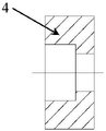
the front end of the fixed claw is a semi-arc surface, the middle of the front end is provided with a knurled screw hole, and the middle of the rear end is provided with a fixed claw mounting hole;
the middle part of the knurled screw is arranged in the knurled screw hole at the front end of the fixing claw;
a clamping head is arranged at the right end of the knurled screw;
the chuck is arranged in the traction groove of the movable insert block.
Preferably, a shouldered nut is mounted to the front end of the stud.
Compared with the prior art, the clamping device for the workpiece with the small positioning surface has the advantages that the structural design is scientific, the problem that the workpiece with the small positioning surface is inconvenient to clamp and compress can be effectively solved, the positioning surface A with the small length on the holding hook can be reliably clamped and compressed, and therefore two round holes in the holding hook can be conveniently and further machined, the machining precision of the round holes is guaranteed, and the clamping device has great production practice significance.
By applying the invention, the processing operation of the round hole on the retaining hook is convenient and quick, the round hole is accurately and reliably processed, and the overall processing efficiency of the retaining hook is greatly improved.
Drawings
FIG. 1a is a top view of a holding hook as a workpiece to be machined;
FIG. 1b is a front view of a holding hook as a workpiece to be machined;
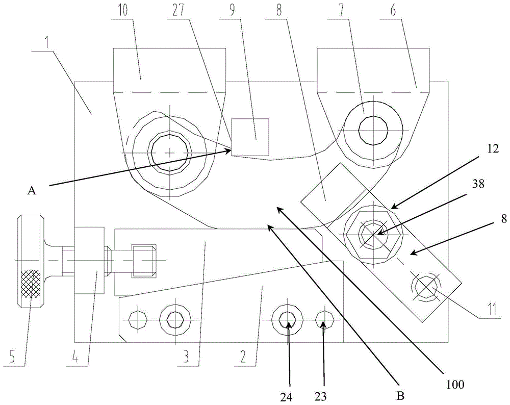
FIG. 2a is a front view of a clamping device for a workpiece with a small positioning surface, which is provided by the invention and is connected with a holding hook as a workpiece to be processed;
FIG. 2b is a left side view of the clamping device for a workpiece with a small positioning surface according to the present invention;
FIG. 2c is a left side view of the clamping device for a workpiece with a small positioning surface, which is provided by the invention, when the knurled screw is removed;
FIG. 2d is a right side view of the clamping device for a workpiece with a small positioning surface according to the present invention;
FIG. 2e is a bottom view of the clamping device for a workpiece with a small positioning surface according to the present invention;
FIG. 2f is a top view of the clamping device for a workpiece with a small positioning surface according to the present invention;
fig. 3a is a front view of a clamp seat in the clamping device for a workpiece with a small positioning surface provided by the invention;
FIG. 3b is a top view of a clamp seat in the clamping device for a workpiece with a small positioning surface according to the present invention;
FIG. 3c is a right side view of the clamp seat of the clamping device for a workpiece with a small positioning surface according to the present invention;
FIG. 3d is a left side view of the clamp seat of the clamping device for a workpiece with a small positioning surface according to the present invention;
FIG. 4a is a front view of a fixed wedge in the clamping device for a workpiece with a small positioning surface according to the present invention;
FIG. 4b is a partial cross-sectional view of a fixed wedge in the clamping device for a workpiece with a small positioning surface according to the present invention;
FIG. 5a is a front view of a movable insert block in the clamping device for a workpiece with a small positioning surface according to the present invention;
FIG. 5b is a left side view of a movable insert block in the clamping device for a workpiece with a small positioning surface according to the present invention;
FIG. 6a is a left side view of a fixing claw in the clamping device for a workpiece with a small positioning surface according to the present invention;
FIG. 6b is a cross-sectional view of a fixing claw in the clamping device for a workpiece with a small positioning surface, provided by the invention;
FIG. 7 is a front view of a knurled screw in the clamping device for a workpiece with a small positioning surface, provided by the invention;
fig. 8a is a front view of a small drill plate in the clamping device for a workpiece with a small positioning surface provided by the invention;
FIG. 8b is a left side view of a small drill plate in the clamping device for a workpiece with a small positioning surface according to the present invention;
FIG. 9 is a transverse sectional view of a drill bushing in the clamping device for a workpiece with a small positioning surface provided by the invention;
FIG. 10a is a transverse cross-sectional view of a pressing plate in the clamping device for a workpiece with a small positioning surface according to the present invention;
FIG. 10b is a front view of a pressing plate of the clamping device for a workpiece with a small positioning surface according to the present invention;
fig. 11a is a front view of a positioning block in the clamping device for a workpiece with a small positioning surface according to the present invention;
fig. 11b is a left side view of a positioning block in the clamping device for a workpiece with a small positioning surface according to the present invention;
FIG. 12a is a front view of a large drill plate in the clamping device for a workpiece with a small positioning surface according to the present invention;
FIG. 12b is a left side view of a large drill plate in the clamping device for a workpiece with a small positioning surface according to the present invention;
FIG. 13 is a top view of a support pin in the clamping device for a workpiece with a small positioning surface according to the present invention;
FIG. 14a is a right side view of a shoulder nut in the clamping device for a workpiece with a small positioning surface according to the present invention;
FIG. 14b is a front view of a shoulder nut in the clamping device for a workpiece with a small positioning surface according to the present invention;
FIG. 15 is a top view of a stud bolt in the clamping device for a workpiece with a small positioning surface according to the present invention;
in the figure, 100 is a retaining hook, 101 is a first round hole, 102 is a second round hole;
1. the clamp comprises a clamp seat, 2 parts of a fixed wedge block, 3 parts of a movable insert block and 4 parts of a fixed claw; 5. knurling screws;
6. the drilling tool comprises a small drilling template, 7 drill bushings, 8 pressing plates, 9 positioning blocks and 10 large drilling template;
11. a support nail, 12, a nut with a shoulder and 13, a shallow groove; 14. drilling a template mounting hole, 151, a first tool outlet hole, 152 and a second tool outlet hole;
16. positioning a square hole; 17. the stud bolt mounting hole, 18, a first threaded hole, 19, a fixed claw mounting groove; 20. a second threaded hole;
21. a pin hole, 22, a first inclined plane, 23, a pin mounting hole; 24. screw mounting holes, 25, second inclined plane;
26. a pressing surface, 27, a positioning block positioning surface; 28. a traction groove, 29, a knurled screw hole, 30, a fixing claw mounting hole;
31. the clamping head 32 is a first drill bushing mounting hole, 33 is a second drill bushing mounting hole, and 34 is a support nail mounting hole; 35. a long round hole;
36. the pressing arc surface, the supporting arc surface and the stud bolt are 37 degrees.
Detailed Description
In order to make the technical means for realizing the invention easier to understand, the following detailed description of the present application is made in conjunction with the accompanying drawings and embodiments. It is to be understood that the specific embodiments described herein are merely illustrative of the relevant application and are not limiting of the application. It should be noted that, for convenience of description, only the portions related to the present application are shown in the drawings.
It should be noted that the embodiments and features of the embodiments in the present application may be combined with each other without conflict. The present application will be described in detail below with reference to the embodiments with reference to the attached drawings.
It should be noted that in the description of the present application, the terms of direction or positional relationship indicated by the terms "center", "upper", "lower", "left", "right", "vertical", "horizontal", "inner", "outer", etc. are based on the directions or positional relationships shown in the drawings, which are merely for convenience of description, and do not indicate or imply that the device or element must have a specific orientation, be constructed and operated in a specific orientation, and thus, should not be construed as limiting the present application.
In addition, it should be noted that, in the description of the present application, unless otherwise explicitly specified and limited, the term "mounted" and the like should be interpreted broadly, and may be, for example, either fixedly mounted or detachably mounted.
The specific meaning of the above terms in the present application can be understood by those skilled in the art as the case may be.
Referring to fig. 1a to 15, the invention provides a clamping device for a workpiece with a small positioning surface, which comprises a clamp seat 1, a fixed wedge 2, a movable insert 3, a fixed claw 4, a knurled screw 5, a small drill plate 6, a drill bushing 7, a pressure plate 8, a positioning block 9, a large drill plate 10, a support nail 11, a nut 12 with a shoulder and a stud 38;
wherein, the left end and the right end of the upper end surface of the clamp seat 1 are respectively provided with a shallow groove 13;
the upper end surfaces of the two shallow grooves 13 which are distributed on the left and the right are respectively provided with the upper end of a large drilling template 10 and the upper end of a small drilling template 6;
wherein, the left and right sides of the upper part of the clamp seat 1 are respectively provided with a first tool outlet 151 and a second tool outlet 152 at the positions corresponding to the first round hole 101 and the second round hole 102 on the holding hook 100 to be processed;
a positioning square hole 16 is arranged between the first cutter outlet hole 151 and the second cutter outlet hole 152;
the longitudinally distributed positioning blocks 9 are arranged in the positioning square holes 16;
wherein, a stud bolt mounting hole 17 is arranged at the right position of the middle part of the clamp seat 1;
wherein, a fixed claw mounting groove 19 is arranged at the left lower part of the clamp seat 1;
the right side of the fixed claw mounting groove 19 is provided with a first threaded hole 18 which is distributed transversely;
a fixing claw 4 mounted in a threaded hole 18 on the right side of the fixing claw mounting groove 19 by a socket head cap screw (the socket head cap screw penetrates through a fixing claw mounting hole 30 on the fixing claw 4);
two first hole combinations are arranged on the left side and the right side of the lower part of the clamp seat 1, and each first hole combination comprises a second threaded hole 20 and a pin hole 21;
the fixed wedge block 2 is fixed at the lower part of the clamp seat 1 through a threaded hole 20 and a pin hole 21 by an inner hexagonal screw and a pin respectively;
the top surface of the fixed wedge block 2 is a first inclined surface 22;
two second hole combinations are arranged on the left side and the right side of the lower part of the fixed wedge block 2, and each second hole combination comprises a pin mounting hole 23 and a screw mounting hole 24;
wherein, the bottom surface of the movable insert 3 is a second inclined surface 25;
wherein the first inclined surface 22 and the second inclined surface 25 are in contact;
wherein, the left end of the movable insert 3 is provided with a traction groove 28 which penetrates through the front and the back;
the front end of the fixed claw 4 is a semicircular arc surface, the middle of the front end is provided with a knurled screw hole 29, and the middle of the rear end is provided with a fixed claw mounting hole 30;
wherein, the middle part of the knurled screw 5 is arranged in the knurled screw hole 29 at the front end of the fixed claw 4;
the right end of the knurled screw 5 is provided with a clamping head 31;
the clamping head 31 is arranged in the traction groove 28 of the movable insert 3, so that the movable insert 3 can move left and right transversely along with the knurled screw 5;
the upper end of the small drill plate 6 and the upper end of the large drill plate 10 are respectively arranged in a shallow groove 13 on the upper end surface of the clamp seat 1 through inner hexagon screws;
the lower end of the small drill plate 6 and the lower end of the large drill plate 10 are respectively provided with a first drill bushing mounting hole 32 and a second drill bushing mounting hole 33;
two drill bushings 7 mounted in the first drill bushing mounting hole 32 and the second drill bushing mounting hole 33, respectively;
wherein, the right end of the pressure plate 8 is provided with a support nail mounting hole 34;
the middle part of the pressure plate 8 is provided with a long round hole 35;
a pressing arc surface 36 is arranged on the rear side of the left end part of the pressing plate 8;
a pressing arc surface 36 which is pressed against the front side surface of the holding hook 100;
the stud 38 longitudinally and vertically penetrates through the long round hole 35 on the pressure plate 8 and then is fixed in the stud mounting hole 17 on the clamp seat 1;
a shoulder nut 12 is mounted (screwed) at the front end of the stud 38;
the positioning blocks 9 are rectangular parallelepipeds distributed longitudinally;
the left end surface of the positioning block 9 is a positioning block positioning surface 27;
the positioning block positioning surface 27 is used for abutting against and pressing against (i.e. closely contacting) the positioning surface a on the holding hook 100;
in the invention, in a concrete implementation, the support nail 11 longitudinally and vertically penetrates through the support nail mounting hole 34 at the right end of the pressure plate 8 and then contacts with the front side surface of the clamp seat 1;
the rear end face of the support nail 11 is a support arc surface 37, and is used for abutting against and pressing against the front side face of the clamp seat 1.
In the present invention, in a specific implementation, the included angles between the first inclined surface 22 and the second inclined surface 25 are equal (consistent) with the horizontal plane, so as to ensure that when the first inclined surface 22 and the second inclined surface 25 are tightly attached to each other in use, the pressing surface 26 on the top of the movable insert block 3 is perpendicular to the positioning block positioning surface 27 of the positioning block 9.
For example, referring to fig. 4b and 5a, the first inclined surface 22 is inclined at an angle α, and the second inclined surface 25 is also inclined at an angle α.
In the invention, in concrete implementation, two drill plate mounting holes 14 which are distributed transversely at intervals are respectively arranged on the upper end surfaces of the two shallow grooves 13;
the small drill plate 6 and the large drill plate 10 are respectively installed in the drill plate installation holes 14 of the two shallow grooves 13 through inner hexagon screws.
In the present invention, in a specific implementation, the left side view and the right side view of the small drill plate 6 and the large drill plate 10 are L-shaped.
In order to more clearly understand the technical solution of the present invention, the following describes the operation process of the present invention.
Firstly, the device is placed on a horizontal workbench, the movable insert block 3 is taken down, and the knurled screw 5 is unscrewed to the position of the chuck 31;
then, the holding hook 100 as a workpiece to be processed is inserted into the apparatus of the present invention from the gap between the front side surface of the jig base 1 and the rear side surface of the left large drill plate 10 and the gap between the front side surface of the jig base 1 and the jig base 1;
then, the position of the holding hook 100 as a workpiece to be processed is adjusted, so that the positioning surface a of the holding hook 100 is closely attached to the positioning block positioning surface 27 at the left end of the positioning block 9;
then, the second inclined surface 25 on the movable insert 3 is in opposite contact with the first inclined surface 22 of the fixed wedge 2, and the chuck 31 is placed in the traction groove 28;
then, the knurled screw 5 is rotated clockwise, so that the movable insert 3 slides along the first inclined surface 22 on the fixed wedge 2 along with the rotation of the knurled screw 5, and the pressing surface 26 of the movable insert 3 is forced to approach and press the short straight surface B of the workpiece to be processed (i.e., the holding hook 100);
then, the shouldered nuts 12 on the stud bolts 38 penetrating through the pressure plate 8 are tightened, that is, the holding hook 100 is clamped, and at this time, the holding hook 100 is processed into the first circular hole 101 and the second circular hole 102 by the existing equipment (for example, a hole processing tool such as a drill on an existing lathe).
Compared with the prior art, the clamping device for the workpiece with the small positioning surface, provided by the invention, has the following beneficial effects:
1. aiming at the condition that a workpiece (a retaining hook 100) with a small positioning surface is easy to separate from the positioning surface when being clamped, the wedge pressing mechanism is adopted to tightly press the workpiece from one side of the positioning surface, so that the workpiece can be prevented from turning over when being pressed;
2. the workpiece positioning structure adopted by the invention can correspond to the rotation direction of the cutter, and the clamping mode of the workpiece of the device enables the drill bit which rotates clockwise in the work to compress the positioning surface, thereby ensuring the precision of the machining size and the machining consistency;
3. the end part of the support nail is provided with the support cambered surface, so that the workpiece with a certain thickness range can be compressed;
4. the long round hole arranged on the pressing plate is convenient for clamping and disassembling the workpiece.
Compared with the prior art, the clamping device for the workpiece with the small positioning surface, which is provided by the invention, has a scientific structural design, can effectively solve the problem that the workpiece with the small positioning surface is inconvenient to clamp and compress, and can reliably clamp and compress the positioning surface A with the small length on the holding hook, so that two round holes on the holding hook can be further processed conveniently, the processing precision of the round holes is ensured, and the clamping device has great production practice significance.
By applying the invention, the processing operation of the round hole on the retaining hook is convenient and quick, the round hole is accurately and reliably processed, and the overall processing efficiency of the retaining hook is greatly improved.
The foregoing is only a preferred embodiment of the present invention, and it should be noted that, for those skilled in the art, various modifications and decorations can be made without departing from the principle of the present invention, and these modifications and decorations should also be regarded as the protection scope of the present invention.